Sungrow AC007UK-01 User Manual
Ac charger
Hide thumbs
Also See for AC007UK-01:
- Quick installation manual (19 pages) ,
- User manual (60 pages) ,
- Quick installation manual (11 pages)

Related Manuals for Sungrow AC007UK-01


Summary of Contents for Sungrow AC007UK-01
- Page 1 AC Charger User Manual AC007UK-01 AC007UK-01AC ChargerUser ManualAC007UK-01- UEN-Ver11-202303 AC007UK-01-UEN-Ver11-202303...
-
Page 3: All Rights Reserved
Software Licenses • It is prohibited to use data contained in firmware or software developed by SUNGROW, in part or in full, for commercial purposes by any means. • It is prohibited to perform reverse engineering, cracking, or any other operations that compromise the original program design of the software developed by SUNGROW. -
Page 4: About This Manual
Please read this manual carefully before using the product and keep it properly in a place for easy access. All contents, pictures, marks, and symbols in this manual are owned by SUNGROW. No part of this document may be reprinted by the non-internal staff of SUNGROW without written authorization. - Page 5 Indicates moderate-risk potential hazards that, if not avoided, may lead to death or serious injury. Indicates low-risk potential hazards that, if not avoided, may lead to minor or mod- erate injury. Indicates potential risks that, if not avoided, may lead to device malfunctions or fi- nancial losses.
-
Page 7: Table Of Contents
Contents All Rights Reserved .....................I About This Manual......................II 1 Safe Introductions ....................1 2 Introduction .......................3 2.1 Introduction ....................3 2.2 Model and Nameplate ..................3 2.3 Appearance and Dimensions................4 2.4 LED Signals ....................4 2.5 Electrical Connection Ports ................5 2.6 System Topology ....................5 3 Installation ......................7 3.1 Installation Requirements................7... - Page 8 6.4 Restore the Charger to Factory Settings............29 7 Commissioning via App .................30 7.1 Download and Install..................30 7.2 Creat your account ..................31 7.3 Connect the charger to Monta................31 7.4 Super powers and customer support ..............31 8 Appendix ......................33 8.1 Technical Data .....................33 8.2 Quality Assurance ..................34 8.3 EU Declaration of Conformity ................35 8.4 Contact Information ..................35...
-
Page 9: Safe Introductions
Safe Introductions This manual contains important instructions for SUNGROW charger that shall be followed during installation, operation, and maintenance. Please review all warnings and notices be- fore installing and using the charger. Do not install or use the charger near flammable, explosive, harsh or combustible materials, chemicals, or vapors. - Page 10 1 Safe Introductions User Manual Be careful when transporting the charger. Do not subject it to strong force or im- pact or pull, twist, tangle, drag, or step on the charger to prevent damage to it or any components. Do not touch the end terminal of the charger with any part of your body or metal objects.
-
Page 11: Introduction
Introduction Introduction The AC007UK-01 charger (hereinafter "charger") is used for AC charging of electric vehicles (EVs) and can be either wall-mounted or pole-mounted, with the following advantages: Ease of Use EV drivers can start and stop charging via RFID charge card or App. When the vehicle is fully charged, the charging will stop. -
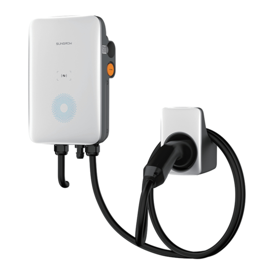
Page 12: Appearance And Dimensions
2 Introduction User Manual Appearance and Dimensions figure 2-1 Appearance and dimensions LED Signals table 2-1 LED Signals Indicator Indicator Blue indicator flashes slowly, on for 1 s and off for 4s ; Standby circulating Charging Blue indicator breathes, on for 1s and off for 1s; circulating Charging stops Blue indicator is steady on Blue indicator flashes quickly, on for 0.5s and off for 0.5s;... -
Page 13: Electrical Connection Ports
Explanation Charging cable output (Charging cable connection) RS485 external communication AC input (AC connection) System Topology Stand-alone EV Charger figure 2-3 System topology diagram of EV charger Description Position Note Utility grid TT, TN-C, TN-S, TN-C-S. Charger AC007UK-01 Electric vehicle... - Page 14 A Li-ion battery. Backup loads Protected house loads directly connected to the inverter. Non-protected house loads. They will be disconnected in Normal loads case of grid failure. Charger AC007UK-01 For Sungrow's solar-storage-EV charging solution, please refer to user manuals of related inverters.
-
Page 15: Installation
Installation Respect all local standards and requirements during mechanical installation. Any damage or malfunction with the charger caused by negligence or improper use will not be eligible for service and replacement under the warranty. Installation Requirements Location Requirements Select an optimal mounting location for safe operation, long service life and expected performance. -
Page 16: Unpacking And Inspection
After receiving the product, check whether the appearance and structural parts of the device are damaged, and check whether the packing list is consistent with the actual ordered product. If there are problems, do not install the device and contact your distributor first. If the problem persists, contact SUNGROW in time. - Page 17 User Manual 3 Installation table 3-1 Label Descriptions Item Name Quantity AC-Charger Charging cable bracket Backplate Upper mounting plate Lower mounting plate Mounting pole (optional) Combination screw and expansion 4, 7 (wall-mounted); 11, 0 (pole- screw mounted) L-shaped spanner RFID charge card Quick Installation Guide, Warranty 1, 1, 1 Card, and Certificate of Conformity...
-
Page 18: Installation Tools
3 Installation User Manual The scope of delivery does not include the optional mounting pole (F), this item must be ordered separately. Installation Tools table 3-2 Label Descriptions Item Name Specification Marker Wire stripper Hammer drill Ø6, Ø12 Philips screwdriver M3, M4 Heat gun RJ45 crimping tool... -
Page 19: Ac Cable Connection
User Manual 3 Installation figure 3-1 Circuit diagram(United Kingdom) table 3-3 Label Descriptions Label Description The LED lights that indicates the status of the charger ESP32 module for Wi-Fi communication CT for leakage current detection Charging connector The charger already integrates a DC residual-current device (RCD) with a rated re- sidual current of 6 mA. - Page 20 3 Installation User Manual step 3 Plug the cable into the port of the power supply which is at the leftmost. step 4 Adjust the cable to a suitable length, and strip off the insulation of the cable to prepare for ca- ble connection terminals.
- Page 21 User Manual 3 Installation Color Terminal Brown Blue Yellow-green step 5 Connect each crimped terminal (OT2.5-5) and tighten them using a screwdriver. (Torque: 3 ± 0.2 N·m) step 6 Put the back cover plate back in place and tighten the screws to secure it. - - End...
-
Page 22: Communication Connection
3 Installation User Manual 3.4.3 Communication Connection The communication connection is only needed to connect the charger to an inver- ter, battery or Wi-Fi connection that is possible for stand-alone usage with Monta. figure 3-2 RJ45 components step 1 Crimp both ends of the Ethernet cable using a crimping tool. Ensure that the blue wire and the blue-white wire is correctly crimped. -
Page 23: Wall-Mounted Installation
User Manual 3 Installation step 4 Ensure that the cable is secured. - - End Wall-Mounted Installation Install the charger on the wall using the provided wall-mounting bracket and expansion screw sets. • Installation height of the charger from ground: 1.1m recommended •... - Page 24 3 Installation User Manual step 2 Install the charging cable bracket. Hold the charging cable bracket in the desired position on the wall and mark the posi- tions of the drill holes. Drill holes at the marked positions using a hammer drill. Insert the dowel into the hole.
- Page 25 User Manual 3 Installation It is recommended that the charging cable bracket be positioned at the lower right side of the charger, about 20 cm away from the charger. The distance shall be ad- justed according to the actual situation. step 3 Mount the charger.
-
Page 26: Pole-Mounted Installation
3 Installation User Manual - - End Installation height of the connector socket from ground: 1.1m recommended, from charger:0.5m recommended figure 3-3 Wall-mounted charger Pole-Mounted Installation It is recommended to install the pole on a solid support surface (such as concrete or tarmac). -
Page 27: Pole Installation
User Manual 3 Installation figure 3-4 Front view and top view (unit: mm) 3.6.2 Pole Installation step 1 Connect the AC cable. Remove the cover plate on the back of the pole using a cross screwdriver. Lead the AC cable through the bottom into the pole. Grab the AC cable when it reaches the cover plate and take out the end of the cable from the AC cable outlet. - Page 28 3 Installation User Manual Insert the dowel into the holes. Tighten the expansion screw using a screwdriver. Check whether the pole is firmly installed. step 3 Install the backplate and the charging cable bracket. Align the holes in the backplate with the holes drilled in the pole, and secure the back- plate to the pole with screws.
- Page 29 User Manual 3 Installation - - End figure 3-5 Pole-mounted charger...
-
Page 30: Inspection Before Commissioning
Inspection before Commissioning table 4-1 Requirements before commissioning Description Item The charger is correctly mounted at a place that is convenient Location for operation and maintenance. Charger The charger is firmly and securely installed. Cables are correctly and firmly connected, and are adequately Cable protected from damage. -
Page 31: Troubleshooting
The grid voltage is still company for solutions if the above 242V after grid voltage is above 242V. overvoltage. Contact Sungrow Customer Service problem persists. Usually, the charger will be re- connected to the grid once the grid returns to normal. If the prob-... - Page 32 Overcur- Output current is above 17.6 A rent Stop charging and pull out the charging connector. Con- tact Sungrow Customer Serv- ice if the problem persists. Restart the charger and try again. Relay Charg- The relay is stuck and cannot...
- Page 33 L and N wires are cor- The cable’s current-carry- Wiring perature rectly connected. ing capacity does not meet the requirements. Contact Sungrow Customer Service problem Reverse L and N wires are connected persists. polarity reversely. table 5-2 LED Signals that indicates abnormal conditions...
- Page 34 Red light is on for 0.5s, off for 0.5s, and flashes 15 times, and Security chip failure then off for 3s. Cyclic Alarms (ground alarm, disassembly Red light is on alarm, reverse phase alarm and etc.) If the above faults cannot be removed, please contact Sungrow.
-
Page 35: Commissioning Via Web Ui
Commissioning via Web UI The charger has a built-in access point for commissioning and connection to other devices. figure 6-1 Web UI The charger's Wi-Fi network will only broadcast for 15 minutes. Once you have connected your mobile device or laptop to the charger, be sure to perform the task within 15 minutes. -
Page 36: Configure Network
6 Commissioning via Web UI User Manual The Home page opens. step 6 On the Home page, select Network Settings. step 7 Click Wi-Fi Name to select your router Wi-Fi network from the list, and enter the pass- word of the router network below. step 8 Click Confirm to apply the changes. -
Page 37: Upgrade The Firmware
User Manual 6 Commissioning via Web UI Description Mode Network Start the charging session on Monta. Plug&Play Start the charging session once the charging connector is plugged into the vehicle. - - End 6.3.2 Upgrade the Firmware Before you start, be sure that your mobile device or laptop has connected to the charger. Please use Safari or Chrome browsers only because other browsers might cause an unexpected error when upgrading. -
Page 38: Commissioning Via App
Commissioning via App Download and Install Monta is the companion app for your charger. After connecting your charger to Monta you can use the app to start charging or share your charger with family and friends. Before you start, make sure your charger is connected to WiFi . step 1 Scan the QR code below and follow the link or search for "Monta EV charging"... -
Page 39: Creat Your Account
User Manual 7 Commissioning via App - - End Creat your account step 1 Open Monta; step 2 Create your account using your phone number or social logins(Apple/Google/Microsoft). - - End Connect the charger to Monta step 1 Open Monta; step 2 Follow the steps to name your charger and set the location. - Page 40 7 Commissioning via App User Manual If you need help, please contact our customer support through the app or via our website Monta.com.
-
Page 41: Appendix
Appendix Technical Data table 8-1 Technical Data Specification AC007UK-01 AC Input and Output Max. charge power 7.4kW Output Voltage AC230V±10% Nominal grid frequency 50/60 Hz 32A single-phase Max. current Charge connector Plug Type 2 cable cross-section 3*6 mm² Cable Length... -
Page 42: Quality Assurance
Warranty 3 years (standard), 5 years (optional) Quality Assurance In the event of a defect during the warranty period, SUNGROW will provide free of charge service or replace the product with a new one. Evidence During the warranty period, the customer shall provide the product purchase invoice and date. -
Page 43: Eu Declaration Of Conformity
The damage is caused by unexpected natural factors. For faulty products in any of the above cases, if the customer requests maintenance, paid maintenance service may be provided based on the judgment of SUNGROW. EU Declaration of Conformity within the scope of the EU directives:... - Page 44 Sungrow Power Supply Co., Ltd. Add: No.1699 Xiyou Rd.,New & High Technology Industrial Development Zone, 230088,Hefei, P. R. China. Web: www.sungrowpower.com E-mail: info@sungrow.cn Tel: +86 551 6532 7834 / 6532 7845 Specifications are subject to changes without advance notice.
Need help?
Do you have a question about the AC007UK-01 and is the answer not in the manual?
Questions and answers