Table of Contents
Advertisement
Quick Links
Instruction manual
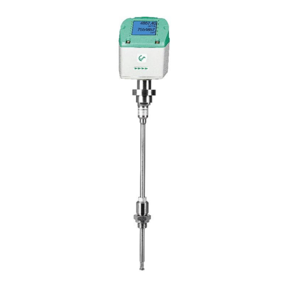
Flow sensor VD 500
with Display, 4 ... 20 mA and Pulse output (galv. isolated)
Stationary and mobile
flow and consumption measurement for compressed air and gases
Sales Office South
Zindelsteiner Straße 15
D-78052 VS-Tannheim
DEUTSCHLAND
Tel.: +49 (0) 7705 978 99-0
Fax: +49 (0) 7705 978 99-20
info@cs-instruments.com
www.cs-instruments.com
VD 500 English V1.07
EN - English
Sales Office North
Gewerbehof 14
D-24955 Harrislee
Deutschland
Tel.: +49 (0) 461 700 20 25
Fax: +49 (0) 461 700 20 26
Seite 1 von 40
Advertisement
Table of Contents

Related Manuals for CS Instruments VD 500


Summary of Contents for CS Instruments VD 500
- Page 1 EN - English Instruction manual Flow sensor VD 500 with Display, 4 ... 20 mA and Pulse output (galv. isolated) Stationary and mobile flow and consumption measurement for compressed air and gases Sales Office South Sales Office North Zindelsteiner Straße 15...
-
Page 2: Table Of Contents
Spot drilling collar with ball valve ..................8 Installation of the Sensor ...................... 9 5.4.1 Mounting VD 500 onto the ball valve ................. 9 5.4.2 Installation angle for locations that potentially hold water ..........10 Display Head Position ......................10 Commissioning ......................11... - Page 3 10.3.4.3 Display / Touch ......................34 10.3.5 Advanced ......................... 34 10.3.6 4 -20mA ........................... 35 10.3.7 VD 500 Info ........................37 10.4 MBus............................37 10.4.1 Default Settings communication ..................37 10.4.2 Default values transmitted ....................37 Status / Error messages ...................38 11.1...
-
Page 4: Intended Use
CS Instruments GmbH is also not liable for consequential damage resulting from the delivery, capability or use of this device. We offer you to take back the instruments of the instruments family VD 500 which you would like to dispose of. -
Page 5: Instruments Description
Instruments description 3 Instruments description The VD 500 is a compact consumption counter for compressed air and gases. Special features: - Optimum accuracy due to compact design - Intgrated Display showing Flow, consuption, velocity and temperature - Input inner tube diameter via display keys - Units free selectable. -
Page 6: Technical Data
TFT 1.8“ Resolution 220 x 176 Display: G ½“, optional ½” NPT Mounting thread: Material: Stainless steel 1.4301 / 1.4404 Protection class IP65 ‘* m.v. = measured values f.s. = full scale VD 500 English V1.07 Seite 6 von 40... -
Page 7: Installation
The values represent the min. lengths. In case the min. inlet / outlet runs could not be ensured, it must be expected to get increased or significant deviations of the measurement values. VD 500 English V1.07 Seite 7 von 40... -
Page 8: Installation Vd 500
In case the system could not be shut down, means to be set depressurized, there could be used the CS spot drilling collar (Order-No. 0530 1108) and drilling jig (Order-No. 0530 1108) to drill through the ball valve. VD 500 English V1.07 Seite 8 von 40... -
Page 9: Installation Of The Sensor
Installation Installation of the Sensor 5.4.1 Mounting VD 500 onto the ball valve • Assembly is carried out by inserting the connection thread with gasket. (G1/2“ thread, SW 32) into the ball valve with ½"internal thread. The sensor has be tighten by hand as far as possible and then tighten with stipulated torque of 25-30 Nm. -
Page 10: Installation Angle For Locations That Potentially Hold Water
Location that potentially hold water should be avoided ! • It is recommended to install the VD 500 at an angle of 15 degrees (see picture).This allows condensate or water to drip off in the event that it is present. -
Page 11: Commissioning
Commissioning Commissioning The consumption sensor VD 500 measures the flow velocity (differential pressure principle) in the center of the pipe. Zero Point Adjustment In order to achieve the required measurement accuracy, a zero point adjustment of the sensor must first be carried out at the start of the measurement. -
Page 12: Measuring Ranges
Measuring ranges Measuring ranges The consumption sensor VD 500 is available in 2 different versions: • High Speed–Version max. measuring range of 224.0 m/s • Ultra Speed –Version max. measuring range of 600.0 m/s The sensors are programmed to pipe inner diameter of 53,1 mm. -
Page 13: Maximum Flow Ranges „High Speed
Measuring ranges The end values refer to application-typical conditions of 7 bara + 50°C. The end values of the consumption sensor VD 500 depend on temperature and pressure and change with changing operating conditions.. 7.1 Maximum Flow ranges „High speed“... -
Page 14: Maximum Flow Ranges „Ultra Speed
600,0 800,0 912017 838682 600,0 900,0 1154271 1061458 600,0 1000,0 1425026 1310441 600,0 Referred to DIN 1945 / ISO 1217 (20°C, 1000mbar) and compressed air. Referred to DIN 1343: 0°C, 1013,25 mbar VD 500 English V1.07 Seite 14 von 40... -
Page 15: Dimension
Dimensions 8 Dimension 416,0 (Standard Schaft 220mm) SW 27 SW 32 220 mm(Standard) Optional: 120, 160, 300, 400 mm Connector plug A Connector plug B VD 500 English V1.07 Seite 15 von 40... -
Page 16: Electrical Wiring
DIP Switch to “On”. It must be ensured that the connection plugs are still plugged and the gasket is installed correctly. Alternatively, a 120R resistor can be installed in the plug between pin 2 and pin VD 500 English V1.07 Seite 16 von 40... -
Page 17: Ethernet (Optional Poe)
Connector plug B Connection cable M12 x-coded 8 pole M12 x-coded to RJ45 Data LINES: 1,2 und 3,4 PoE LINES: 5,6 und 7,8 M12 x 1 Connection cable: Cat 6. *PoE: Power over Ethernet VD 500 English V1.07 Seite 17 von 40... -
Page 18: Operation
Remark: In version with display only. “OK“ ( ) “Up“ ( The operation of the VD 500 is done by the two capacitive key buttons Up ( ) und Enter ( VD 500 English V1.07 Seite 18 von 40... -
Page 19: Initialization
Operation 10.1 Initialization After switching on the VD 500, the initialized screen is displayed followed by the main menu. 10.2 Main menu *** VA 500 *** *** VD 500 *** Gas / Status Info HW Version Modbus ID Page-No. SW Version ... -
Page 20: Settings
Selection of a menu item or to change a value „ “, a final move to the is done with the key chosen menu item or takeover of the value change needs the confirmation by pressing the „OK“ VD 500 English V1.07 Seite 20 von 40... -
Page 21: Sensor Setup
, select the respective position and activate the position with the "OK" button. „“ By pressing the position value is incremented by 1. Complete with "OK" activate next number position. „OK“. Confirm entry by pressing VD 500 English V1.07 Seite 21 von 40... -
Page 22: Input / Change Consumption Counter
In case the quantity of units selectable are not presentable on one page, pleas move to next „<<“ page by pressing Confirm selection by pressing 2x „OK“. Procedure for all 4 measurement variables is analogous. VD 500 English V1.07 Seite 22 von 40... -
Page 23: Definition Of The Reference Conditions
1. Complete with "OK" activate next number position. Procedure for changing the reference temperature is the same. VD 500 English V1.07 Seite 23 von 40 Under point "Filtertime" together with the appropriate "Filter Grade"... - Page 24 "Filter Type" button and changing with "OK". Normal: for all general measurements. Fast: For measurements with very fast changes in measured values Slow: for measurements after the compressor (pulsating flow) Translated with www.DeepL.com/Translator VD 500 English V1.07 Seite 24 von 40...
-
Page 25: Setting Of Zeropoint And Low-Flow Cut Off
„Reset“ „ZeroPnt“ By selection of all settings for and. „CutOff“ are reset. 1,03 „“ Menu item to be select with button and confirm „OK“ the reset with „Back“ Leave menu with button VD 500 English V1.07 Seite 25 von 40... -
Page 26: Modbus Settings
Operation 10.3.2 Modbus Settings 10.3.2.1 Modbus RTU Setup The Flow sensors VD 500 comes with a Modbus RTU Interface. Before commissioning the sensor the communication parameters • Modbus ID, Baudrate, Parity und Stop bit must be set in order to ensure the communication with the Modbus master. -
Page 27: Modbus Tcp (Optional)
It must be ensured that the connection plugs are still plugged and the gasket is installed correctly, see also chapter 4.5. 10.3.2.2 Modbus TCP (Optional) The Flow sensors VD 500 comes optional with a Modbus TCP Interface (HW Interface:M12 x 1 X-coded connector). Device supports with this option the Modbus TCP protocol for communication with SCADA systems. -
Page 28: Network Settings Static Ip
"OK" key. Change the values with the ">" key, and accept the values with the "OK" key. Procedure for "Subnet" "Gateway" analogous. „Save“ Store the settings by VD 500 English V1.07 Seite 28 von 40... -
Page 29: Modbus Tcp Settings
(Little Endian) and "CDAB" (Middle Endian) Saving the changes by pressing "Save", „>“ therefore select it with key and then confirm it with "OK". Reset to the default settings by activating "Set to Default"- VD 500 English V1.07 Seite 29 von 40... -
Page 30: Modbus Settings Register (2001
1180 Float 1189 1188 Float Flow in Ncfm 1197 1196 Float Flow in kg/h Flow in kg/min 1205 1204 Float Flow in kg/s 1213 1212 Float Flow in kW 1221 1220 Float VD 500 English V1.07 Seite 30 von 40... - Page 31 • For DS400 / DS 500 / Handheld devices - Modbus Sensor Datatype „ Data Type R4-32“ match with „Data Type Float“ • For more additional Modbus values please refer to VA5xx_Modbus_RTU_Slave_Installation_1.07_EN.doc VD 500 English V1.07 Seite 31 von 40...
-
Page 32: Pulse /Alarm
3000000 Table 1 Maximum flow for pulse output Entering pulse values that are not allow a presentation to the full scale value, are not allowed. Entries are discarded and error message displayed. VD 500 English V1.07 Seite 32 von 40... -
Page 33: User Setup
10.3.4.2 Language → → Settings UserSetup Language Currently 4 languages have been implemented and could be selected with button „“. Change of language by confirming with “OK”. “back”. Leaving the menu with button VD 500 English V1.07 Seite 33 von 40... -
Page 34: Display / Touch
10s. To do this, use the "OK" button to enter the operating menu during this period 10.3.5 Advanced Settings → Advanced „Factory Reset“ By pressing the sensor is set back to the factory settings. VD 500 English V1.07 Seite 34 von 40... -
Page 35: -20Ma
„OK“ and confirm selection by pressing → Settings → 4-20mA Channel 1 The 4-20 mA Analogue output of the Sensor VD 500 can be individually adjusted. It is possible to assign following values „Temperature“, „Velocity“ und „Flow“ to the channel CH 1. - Page 36 „“ „OK“ with button and then select by pressing the the desired mode „Save“ For saving the changes done press button “Cancel”. discard the changes press button Leaving the menu with „Back“. VD 500 English V1.07 Seite 36 von 40...
-
Page 37: Vd 500 Info
Operation 10.3.7 VD 500 Info → → Setup Sensor Setup Info Here you get a brief description of the sensor data incl. the calibration data. 92,7 m/s 600m³/h Under Details, you are able to see in addition the calibration conditions. -
Page 38: Status / Error Messages
11.1 Status messages • On the part of CS Instruments GmbH & Co.KGr a regular re-calibration is recommended, see chapter At delivery, the date at which the next recalibration is recommended is internally entered. When this date is reached, a message appears in the display with the status message „CAL“. -
Page 39: Error Messages
„Low Voltage 4-20mA“ is displayed. Error messages: *** VA 520 *** *** VA 520 *** Low Voltage Internal Error *** VA 520 *** *** VA 520 *** Temp out of Range Low Voltage 4.20mA VD 500 English V1.07 Seite 39 von 40... -
Page 40: Maintenance
The warranty time for the VD 500 is 12 months. If no other definitions are given the accessory parts have a warranty time of 6 months. Warranty services do not extend the warranty time.
Need help?
Do you have a question about the VD 500 and is the answer not in the manual?
Questions and answers