
Subscribe to Our Youtube Channel
Related Manuals for CS Instruments VA 525


Summary of Contents for CS Instruments VA 525
- Page 1 EN – English Instruction manual VA 525 Compact inline flow sensor with integrated flow straightener VA 525 EN V1.01 Page 1 of 41...
-
Page 2: Foreword
Foreword Dear customer, thank you very much for deciding in favour of the VA 525. Please read this installation and operation manual carefully before mounting and initiating the device and follow our advice. A riskless operation and a correct functioning of the... -
Page 3: Table Of Contents
Safety instructions ......................5 Instruments description ....................6 Technical data ....................... 7 Scaling Analogue output Comprssed Air ..............8 Installation Description ....................9 Installation of VA 525 ......................9 Flow measuring ranges ....................10 Flow for different gases....................... 10 Dimensions ........................11 Electrical wiring ......................12 Modbus RTU, 4…20mA, Pulse, MBus or Ethernet ............ - Page 4 10.3.5.3 Display / Touch ......................33 10.3.6 Advanced ......................... 33 10.3.7 4 -20mA ........................... 34 10.3.8 VA 525 Info ........................36 10.4 MBus............................37 10.4.1 Default Settings communication ..................37 10.4.2 Default values transmitted ....................37 Status / Error messages ...................38 11.1...
-
Page 5: Intended Use
We are also not liable for consequential damage resulting from the delivery, capability or use of this device. We offer you to take back the instruments of the instruments family VA 525 which you would like to dispose of. -
Page 6: Instruments Description
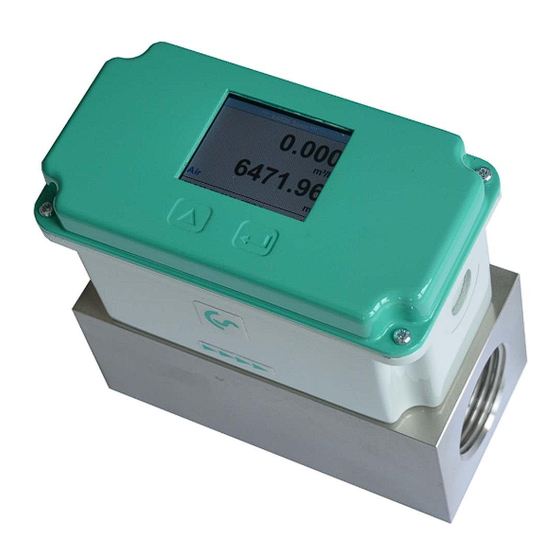
3 Instruments description The newly developed VA 525 combines modern digital interfaces for connection to energy monitoring systems with a small, compact design. The VA 525 is always used when many machines (compressed air consumers) are to be connected/integrated to a energy monitoring network. -
Page 7: Technical Data
G ¼”,, G ½”, G ¾”, G1", G 1¼” G 1½”, G 2” Mounting thread: measuring block Material measuring block: Aluminium Protection calss: IP65 * m.v. = measured values f.s. = full scale VA 525 EN V1.01 Page 7 of 41... -
Page 8: Scaling Analogue Output Comprssed Air
Reference DIN1945/ ISO 1217: 20°C, 1000 mbar (Reference during calibration) Description Version Analogue output Low Speed 0...25 l/min Standard 0...50 l/min VA 525 with integrated ¼” measuring block 4… 20 mA = 0...105 l/min High Speed 0...130 l/min Low Speed 0...20 m³/h Standard 0...45 m³/h... -
Page 9: Installation Description
Measuring ranges 6 Installation Description Installation of VA 525 The sensor VA 525 is pre-supplied with the measuring block. An installation at customer site is only allowed in the unpressurized state of the system. Tightness of the connection must be checked and ensured. -
Page 10: Flow Measuring Ranges
1380 Low Speed Standard Nitrous oxide 1170 High Speed 1420 Other gases on request Please note: The area outside the pipeline (ambient area of the sensor) must not be an explosive area. VA 525 EN V1.01 Page 10 of 41... -
Page 11: Dimensions
G 1/4" 109,1 DN 15 G 1/2" 109,1 DN 20 109,1 G 3/4" DN 25 G 1" 109,1 DN 32 139,1 G1 1/4" DN 40 G1 1/2" 139,1 DN 50 G 2" 139,1 VA 525 EN V1.01 Page 11 of 41... -
Page 12: Electrical Wiring
M12 Connector plug supplied with a M12 connector plug. The user can connect the View from back side supply and signal cables as (terminal side) indicated in the connection diagram. VA 525 EN V1.01 Page 12 of 41... -
Page 13: Connection Diagrams
Grau / Grey - VB Blau / Blue Schwarz / Black Weiss / White 9.2.3 MBus Braun / Brown + VB Blau / Blue - VB Schwarz / Black MBus Grau / Grey MBus VA 525 EN V1.01 page 13 o 41... -
Page 14: Ethernet (Optional Poe)
Connector plug B Connection cable M12 x-coded 8 pole M12 x-coded to RJ45 Data LINES: 1,2 und 3,4 PoE LINES: 5,6 und 7,8 M12 x 1 Connection cable: Cat 6. *PoE: Power over Ethernet VA 525 EN V1.01 page 14 o 41... -
Page 15: Operation
Only for version with display “OK“ ( ) “Up“ ( ) The operation of the VA 525 is done by the two capacitive key buttons Up ( ) and Enter ( VA 525 EN V1.01 Page 15 of 41... -
Page 16: Initialization
Operation 10.1 Initialization After switching on the VA 525, the initialized screen is displayed followed by the main menu. 10.2 Main menu after switching on VA 525 *** VA 520 *** Gas / S tatus in fo HW V ersio n... -
Page 17: Settings
„OK“ Menu items 4..20mA / pulse alarm, Network setup MBus only available with corresponding sensor version. VA 525 EN V1.01 page 17 o 41... -
Page 18: Settings Setup
“OK“. 10.3.1.1 Input / change tube diameter For the VA 525 not adjustable (suspended) as voted on included measuring section with corresponding measurement block diameter. VA 525 EN V1.01 page 18 o 41... -
Page 19: Input / Change Consumption Counter
In case the quantity of units selectable are not presentable on „<<“ one page, pleas move to next page by pressing Confirm selection by pressing 2x „OK“. Procedure for all 4 measurement variables is analogous. VA 525 EN V1.01 page 19 o 41... -
Page 20: Advanced Settings
Do not enter the operation pressure or the operation temperature under reference conditions Setup Sensor Setup Advanced Ref. Settings To make changes, first select a menu with „“ button and confirm selection by pressing „OK“ VA 525 EN V1.01 page 20 o 41... - Page 21 Direct selection of the unit button and „OK". call of the unit page with All changes have to be stored by pressing „Save“. „Default“. With the sensor is reset to calibration settings. VA 525 EN V1.01 page 21 o 41...
-
Page 22: Time Setting For Filtering
Setup Sensor Setup Advanced Ref. Settings AV-Time The time period for averaging can be entered here. Input values of -1440 1 [minutes] are possible. average values see display window 3 + 4 VA 525 EN V1.01 page 22 o 41... -
Page 23: Setting Of Zeropoint And Low-Flow Cut Off
Setup Sensor Setup ZP Adjust t Reset „Reset“ By selection of all settings for „ZeroPnt“ and. „CutOff“ are reset. „“ Menu item to be select with button „OK“ confirm the reset with „Back“ Leave menu with button VA 525 EN V1.01 page 23 o 41... -
Page 24: Pressur Settings
"OK" key. Enter the corresponding pressure value in the input menu and save changes with "OK". Press the "CLR" key to reset the value. Exit the menu with "Cancel". VA 525 EN V1.01 page 24 o 41... -
Page 25: Modbus Settings
Operation 10.3.2 Modbus settings 10.3.2.1 Modbus RTU Setup The Flow sensors VA 525 comes with a Modbus RTU Interface. Before commissioning the sensor the communication parameters Modbus ID, Baudrate, Parity und Stop bit must be set in order to ensure the communication with the Modbus master. -
Page 26: Ethernet (Modbus Tcp)
Operation 10.3.3 Ethernet (Modbus TCP) The Flow sensors VA 525 comes optional with a Modbus TCP Interface (HW Interface:M12 x 1 X-coded connector). Device supports with this option the Modbus TCP protocol for communication with SCADA systems. TCP port is set to 502 by default. Port can be changed at the sensor or using PC Service Software Modbus device address (Unit Identifier) can be set in the range of 1- 255. -
Page 27: Network Settings Static Ip
"OK" key. Change the values with the ">" key, and accept the values with the "OK" key. Procedure for "Subnet" "Gateway" analogous. „Save“ Store the settings by VA 525 EN V1.01 page 27 o 41... -
Page 28: Modbus Tcp Settings
(Little Endian) and "CDAB" (Middle Endian) Saving the changes by pressing "Save", „>“ therefore select it with key and then confirm it with "OK". Reset to the default settings by activating "Set to Default"- VA 525 EN V1.01 page 28 o 41... -
Page 29: Modbus Settings (2001
1180 Float Flow in Ncfm 1189 1188 Float Flow in kg/h 1197 1196 Float 1205 1204 Float Flow in kg/min 1213 1212 Float Flow in kg/s 1221 1220 Float Flow in kW VA 525 EN V1.01 page 29 o 41... - Page 30 For DS400 / DS 500 / Handheld devices - Modbus Sensor Datatype „ Data Type R4-32“ match with „Data Type Float“ For more additional Modbus values please refer to VA5xx_Modbus_RTU_Slave_Installation_1.04_EN.doc VA 525 EN V1.01 page 30 o 41...
-
Page 31: Pulse /Alarm
3000000 Table 1 Maximum flow for pulse output Entering pulse values that are not allow a presentation to the full scale value, are not allowed. Entries are discarded and error message displayed. VA 525 EN V1.01 page 31 o 41... -
Page 32: User Setup
10.3.5.2 Language Settings UserSetup Language Currently 4 languages have been implemented „“ and could be selected with button Change of language by confirming with “OK”. “back”. Leaving the menu with button VA 525 EN V1.01 page 32 o 41... -
Page 33: Display / Touch
10s. To do this, use the "OK" button to enter the operating menu during this period 10.3.6 Advanced Settings Advanced „Factory Reset“ By pressing the sensor is set back to the factory settings. VA 525 EN V1.01 page 33 o 41... -
Page 34: -20Ma
„OK“ and confirm selection by pressing Settings 4-20mA Channel 1 The 4-20 mA Analogue output of the Sensor VA 525 can be individually adjusted. It is possible to assign following values „Temperature“, „Velocity“ und „Flow“ to the channel CH 1. - Page 35 „“ „OK“ with button and then select by pressing the the desired mode „Save“ For saving the changes done press button “Cancel”. discard the changes press button Leaving the menu with „Back“. VA 525 EN V1.01 page 35 o 41...
-
Page 36: Va 525 Info
Operation 10.3.8 VA 525 Info Settings Info Here you get a brief description of the sensor data incl. the calibration data. 92,7 m/s 600m³/h Under Details, you are able to see in addition the calibration conditions. Run Time: 2d 21h 23m 12s... -
Page 37: Mbus
Consumption [m³] Value 2 with [Unit]*: Flow [m³/h]Consumption [m³] Value 3 with [Unit]*: Gas temperature [°C] *All Values could be changed / preset in production or with CS Service software (Order-No. 0554 2007) VA 525 EN V1.01 page 37 o 41... -
Page 38: Status / Error Messages
11.1 Status messages On the part of CS Instruments GmbH & Co.KG a regular re-calibration is recommended, see chapter 13. At delivery, the date at which the next recalibration is recommended is internally entered. When this date is reached, a message appears in the display with the status message „CAL“. -
Page 39: Error Messages
VA 525 Low Voltage Heater Error *** VA 520 *** VA 525 *** VA 520 *** VA 525 Internal Error Temp out of Range *** VA 520 *** VA 525 Low Voltage 4.20mA VA 525 EN V1.01 page 39 o 41... -
Page 40: Maintenance
The warranty time for the VA 525 is 12 months. If no other definitions are given the accessory parts have a warranty time of 6 months. Warranty services do not extend the warranty time. - Page 41 CE Conformity KONFORMITÄTSERKLÄRUNG DECLARATION OF CONFORMITY CS Instruments GmbH & Co.KG Am Oxer 28c, 24955 Harrislee Erklären in alleiniger Verantwortung, dass das Produkt Declare under our sole responsibility that the product Verbrauchs-/ Durchflusssensor VA 525 Flow Sensor VA 525 den Anforderungen folgender Richtlinien entsprechen: We hereby declare that above mentioned components comply with requirements of the following EU directives: Elektromagnetische Verträglichkeit...
Need help?
Do you have a question about the VA 525 and is the answer not in the manual?
Questions and answers