Table of Contents
Advertisement
Quick Links
Advertisement
Table of Contents

Related Manuals for CS Instruments FA 550


Summary of Contents for CS Instruments FA 550
- Page 1 INSTRUCTION MANUAL FA 550 with 3-wire technology 4…20 mA and RS CS dew point sensor FA 550 485 Modbus output enables a reliable and long-term stable monitoring of the dew point in industrial applications such as in Page 1 FA 550 V1.00...
-
Page 2: Table Of Contents
12.3.4 Modbus TCP (Optional) ..................27 12.3.5 Alarm ........................30 12.3.6 User Setup......................31 12.3.7 4 -20mA ......................32 12.3.8 FA 550 Info ......................34 13 Calibration / Adjustment ....................35 14 Warranty ........................... 35 15 Ordering details ........................ 36 Page 2 FA 550 V1.00... -
Page 3: Foreword
FA 550. Please read these installation and operating instructions carefully before installation and commissioning and follow our instructions. The proper functioning of the FA 550 and safe operation can only be ensured if the regulations and instructions described are strictly observed. -
Page 4: Pictograms And Symbols
As a consequence of incorrect handling: possible personal injury or damage Note! Possible harzard As a consequence of incorrect handling: possible personal injury or damage Important! Additional notes, information, tips As a consequence of incorrect handling: Disadvantages in operation and maintenance, no danger Page 4 FA 550 V1.00... -
Page 5: Intended Use
Intended Use Intended use The FA 550 dew point sensor is intended for measuring the dew point or the pressure dew point in clean, dry and oil-free gases and compressed air. It is the responsibility oft he user whether the instrument is suitable for the selected application. -
Page 6: Device Description
Intended Use Device description The FA 550 dew point sensor enables a reliable and long-term stable monitoring of the dew point in industrial applications. When mounting FA 550 into compressed air systems the pressure dew point (dew point under pressure) up to 50 bar (in the special version up to 500 bar) is measured directly. -
Page 7: Safety Instructions
Opening the instrument, improper handling or use of force will void all warranty claims! Important: Before installation, briefly allow compressed air to flow off to remove condensate and particles, this will prevent soiling of the FA 550. Standing air leads to long measuring times. Page 7... -
Page 8: Technical Data
NC relay, relays is closed in case of alarm and power failure. Alarm value adjustable via keyboard. See Chapter Operation. * Peak AC Note: Parallel use of both outputs (4...20mA and RS 485 Modbus) is possible. Page 8 FA 550 V1.00... -
Page 9: Signal Circuits
4 … 20 mA < 500 Ohm 7.1.2.2 Passive Galvanically isolated 4 … 20 mA < 500 Ohm Vin 12-36Vdc 7.1.3 Alarm Galvanically isolated (dry contact) Max. 48Vdc, 500mA Page 9 FA 550 V1.00... -
Page 10: Dimension
Dimensions Dimension Page 10 FA 550 V1.00... -
Page 11: Electrical Wiring
Standard version with 1x analogue output (not galvanically isolated) Option Board 4-20mA I (4-20mA) I (4-20mA) Main Board Version with option board 2x analogue outputs galvanically isolated Option Board MBus MBUS Main Board Version with option board MBus Page 11 FA 550 V1.00... -
Page 12: The Current Outputs, X5 And X6, Are Optional.(Active And Passive Version Available)
Alarm * Alarm * I- Active** I+ Active ** I- Active ** I+ Active ** MBus MBus * Outputs are galvanically isolated. ** The Current outputs, X5 and X6, are optional.(Active and passive version available). Page 12 FA 550 V1.00... -
Page 13: Wire Connection
If the sensor placed at the end oft he Modbus system a termination is required. Therfore the enclosed 120R resistor is to be connected at Pin 1 and Pin 3 of connector „X2“ Main Board 120R Page 13 FA 550 V1.00... -
Page 14: Modbus Tcp (Ethernet) Optional Poe
PoE LINES: 5,6 und 7,8 M12 x 1 Connection cable: Cat 6. *PoE: Power over Ethernet 9.3.5 Pulse Output Main Board Potentialfreier Schaltkontakt Max. 48Vdc , 500mA Remark: The sensor must be connected only in strain less state Page 14 FA 550 V1.00... -
Page 15: Installation
If carrying out welding work on the pipeline the grounding of the welding unit is not allowed to be done over the FA 550 itself. The installer has to ensure that the FA 550 is connected according to the electrical connection diagrams properly. ... - Page 16 Measurable gases In general, humidity can be measured in all non- corrosive gases. In case of measurements in corrosive gases please consult CS Instruments GmbH Page 16 FA 550 V1.00...
-
Page 17: Modbus
Modbus ID, Baud rate, Parity und Stop bit must be set in order to ensure the communication with the Modbus master. The adjustment can be done either with the CS Instruments PC service software, DS 400, DS 500 and the hand-held instrument PI 500 done. -
Page 18: Modbus Settings (2001
13 = Atmospheric DewPoint [°F] 2009 2008 float 4mA Scale Low 2011 2010 float 20mA Scale High Modbus installation, Modbus settings and further information refer to the manual CS Instruments "Modbus Installation and Operating Instructions FA 5xx sensors" Page 18 FA 550 V1.00... -
Page 19: Operation
Operation 12 Operation Die Bedienung des FA 550 erfolgt mittels 2 optischen Tasten, deren Bedienung direkt über / durch die Glasabdeckung erfolgt. Somit kann der FA 550 ohne öffnen des Deckels von außen bedient werden. Optische Tasten Die Auswahl der einzelnen Menüpunkte erfolgt durch die Taste „>“ und Bestätigung durch Taste „OK“... -
Page 20: Initialization
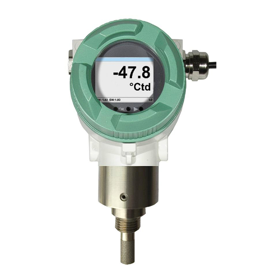
Operation 12.1 Initialization After switching on the FA 550, the initialized screen is displayed followed by the main menu. 12.2 Main menu Page 1 Display value is the pressure dew point, here in °Ctd. (When measured under pressure) The pressure dew point is always based on the pressure in the compressed air pipe. -
Page 21: Settings
Selection of a menu item or to change a „ “, a value is done with the key final move to the chosen menu item or takeover of the value change needs the „OK“ confirmation by pressing the key Page 21 FA 550 V1.00... -
Page 22: Sensor Settings
In case the quantity of units selectable are not presentable on one page, pleas move to next „<<“ page by pressing Confirm selection by pressing 2x „OK“. Procedure for all 3 measurements variables is analogous. „back“ Leaving the menu with Page 22 FA 550 V1.00... -
Page 23: Definition Of Reference- And System Pressure
(overpressure) with 6bar must be entered. Only after entering the two pressures, a correct calculation of the atmospheric dew point is possible. (Displayed on screen page 3, here the value 4) Page 23 FA 550 V1.00... - Page 24 Complete input/change with "OK" and activate next number position. Inputs / changes to be confirmed with „OK“. button Procedure for entering / changing the system pressure is analogous. Settings Sensor Setup Pressure Sys. Pressure Page 24 FA 550 V1.00...
- Page 25 „Calibrate“ By pressing the button the new reference value will be taken over. -24.675 °Ctd A calibration could be set back to „out of factory“ settings with button „Reset“. „back“ Leaving the menu with Page 25 FA 550 V1.00...
-
Page 26: Modbus Rtu Setup
Operation 12.3.3 Modbus RTU Setup The dew point sensor FA 550 comes with a Modbus RTU Interface. Before commissioning the sensor the communication parameters Modbus ID, Baud rate, Parity und Stop bit must be set in order to ensure the communication with the Modbus master. -
Page 27: Modbus Tcp (Optional)
Operation 12.3.4 Modbus TCP (Optional) 12.3.4.1 Setup The dew point sensor FA 550 comes optional with a Modbus TCP Interface (HW Interface:M12 x 1 X-coded connector). Device supports with this option the Modbus TCP protocol for communication with SCADA systems. - Page 28 Select the desired position with the ">" and activate it with the "OK" key. Change the values with the ">" key, and accept the values with the "OK" key. Procedure for "Subnet" "Gateway" analogous. „Save“ Store the settings by Page 28 FA 550 V1.00...
- Page 29 "ABCD" (Little Endian) and "CDAB" (Middle Endian) Saving the changes by pressing "Save", „>“ therefore select it with key and then confirm it with "OK". Reset to the default settings by activating "Set to Default"- Page 29 FA 550 V1.00...
-
Page 30: Alarm
-60°Ctd. „Hysterese“ defines the hysteresis value With button „overrun“ or. „underrun“ the way how the alarm is triggered „Value“ Overrun: Value is exceeding the „Value“ Underrun: Value is going below Page 30 FA 550 V1.00... -
Page 31: User Setup
„Rotate Screen“ will rotate the display content by 180°. Currently there are 4 languages integrated which could be selected by means of button „“. Language activation with activation of „back“ „OK“ button and confirming with Page 31 FA 550 V1.00... -
Page 32: -20Ma
To select a measurement value, a corresponding / appropriate unit needs to be defined. Select „Unit“ „“ „OK“. with and open the menu with „“ Select required unit with and takeover it by „OK“. pressing Page 32 FA 550 V1.00... - Page 33 Channel 1 Scale Input is analogous to that described above, 20mA „CLR“ using the the complete entry will be deleted. Takeover the inputs/changes with „Save“, or „Cancel“. discard the changes with „back“ Leaving menu with Page 33 FA 550 V1.00...
-
Page 34: Fa 550 Info
„back“ With change to the settings menu. 12.3.8 FA 550 Info Settings Info Here you get a brief description of the sensor data incl. some production data Page 34 FA 550 V1.00... -
Page 35: Calibration / Adjustment
The calibration cycles should fit your internal scheme. In the course of the DIN ISO certification, we recommend for FA 550 a calibration cycle of one year. If requested we can carry out the calibration on your premises. -
Page 36: Ordering Details
Ordering Details 15 Ordering details Bestell Nr. Beschreibung 0699.0501 FA 550 dew point sensor Option: A1-- -80..+20 °Ctd A2 ---20..+50 °Ctd A3 ---40..+30 °Ctd A4 ---60..+30 °Ctd 0553.0104 Connection cable, length: 5 m 0553.0105 Connection cable, length:10 m 0699.3390 Standard measuring chamber for compressed air up to 16 bar 0699.3290... - Page 37 Page 37 FA 550 V1.00...
Need help?
Do you have a question about the FA 550 and is the answer not in the manual?
Questions and answers