Advertisement
Quick Links
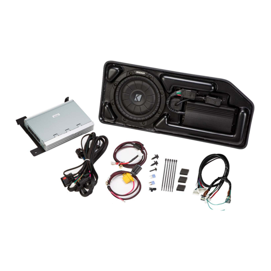
Amplifier Assembly
Subwoofer Harness
©2022 Stillwater Designs
19418149-20220920
Not Compatible with Bose® system
Subwoofer Power Harness
Amplifier Power Harness
19418149
Designed for 2019 and newer
Chevrolet® Colorado and
GMC® Canyon Crew Cab
without HD radio
Subwoofer Assembly
M6 Bolt X 2
7mm Screw
Threaded Clip
Amplifier Harness
Fuse X 2
Wire Tie X 6
Foam Pad X 3
1
Advertisement

Subscribe to Our Youtube Channel
Related Manuals for Kicker 19418149


Summary of Contents for Kicker 19418149
- Page 1 19418149 Designed for 2019 and newer Chevrolet® Colorado and GMC® Canyon Crew Cab without HD radio Not Compatible with Bose® system Subwoofer Assembly Amplifier Assembly Subwoofer Harness M6 Bolt X 2 Subwoofer Power Harness 7mm Screw Amplifier Power Harness Threaded Clip Amplifier Harness Fuse X 2 Wire Tie X 6 Foam Pad X 3 ©2022 Stillwater Designs 19418149-20220920 ...
- Page 2 1. Disconnect negative battery cable. 2. Make sure supplied fuses are not installed in fuse holders. Open the battery distribution cover and connect the subwoofer power wire and the amplifier power wire to the stud pictured in figure 1 depending on which distribution block you have. Torque to 4.7Nm (42in-lb) 3.
- Page 3 6. Install the black two pin power connector on the subwoofer power harness by first inserting the Then depress terminal fully into the connector and then blue depressing the blue retainer. Fig. 4 retainer Insert terminal first Note: Make sure the blue retainer in the center of the connector is not depressed –...
- Page 4 12. Remove the five screws and one plastic retainer securing the passenger side lower cover panel below the glove compartment. To remove the plastic retainer, pry the center portion out first. Fig. 9 Note: Some models may have a smaller panel with only three screws.
- Page 5 16. Temporarily disconnect the HVAC blower fan wiring to allow the amplifier to be installed. 17. Secure the top of the multi-channel amplifier bracket with the supplied M6 bolt – leave loose. Fig. 13 18. Install the supplied M6 bolt to secure the bottom of the multi-channel amplifier bracket to the clip nut –...
- Page 6 22. Connect the tan connector of the amplifier harness back to the radio module. 23. Disconnect the 28-pin green connector from the radio module. Carefully cut away approximately 3 inches of black cloth wrapping the harness. Find the green with black stripe wire and cut.
- Page 7 31. Connect the subwoofer harness two-pin power connector to the power harness two-pin connector. 32. Route the subwoofer input connector (two-pin white) under the dash toward the passenger side and connect it to the multi-channel amplifier connector. 33. Ground the subwoofer harness to the bolt securing Fig.
- Page 8 39. Reinstall the rear seat frame trim panel over the subwoofer enclosure and reinstall the bolts and bumpers. It may be necessary to make slight adjustments to the subwoofer enclosure or rear seat trim panel position to perfectly center the enclosure.
- Page 9 Troubleshooting the Kicker Integrated Systems If you experience a problem once the subwoofer or amplifier are installed use this guide to locate the trouble. The radio is working, but the Subwoofer is not working: Check the battery voltage to make sure it is not discharged below 11 volts.
- Page 10 Splicing Technique Splicing Copper Wire Using Splice Sleeves Special Tools: • EL-38125-10 Splice Sleeve Crimping Tool • J-38125-5A Ultra Torch Special Tool • J-38125-8 Splice Sleeve Crimping Tool NOTE: The DuraSeal splice sleeves have the following 2 critical features: • A special heat shrink sleeve environmentally seals the splice. The heat shrink sleeve contains a sealing adhesive inside.
- Page 11 Open the harness by removing any tape: • Use a sewing seam ripper, available from sewing supply stores, in order to cut open the harness in order to avoid wire insulation damage. • Use the DuraSeal splice sleeves on all types of insulation except Tefzel and coaxial. Cut as little wire off the harness as possible.
- Page 12 The J-38125-8 splice sleeve crimping tool has three crimp nests. The largest crimp nest (3) is used for crimping 10 and 12 gauge wires. The second largest crimp nest (2) is used for crimping 14 and 16 gauge wires. The smallest crimp nest (1) is used for crimping 18 to 20 gauge wires.
- Page 13 If you continue to experience problems after troubleshooting, please contact KICKER Technical Support at 405-533-7499 oesupport@kicker.com P.O. Box 459 • Stillwater, Oklahoma 74076 • USA • (405) 624–8510 ...
Need help?
Do you have a question about the 19418149 and is the answer not in the manual?
Questions and answers