Table of Contents
Advertisement
Advertisement
Table of Contents

Related Manuals for Boss DM-101


Summary of Contents for Boss DM-101
- Page 1 DM-101 Reference Manual...
-
Page 2: Table Of Contents
Table of contents Table of contents Panel Descriptions ........................................ 3 Top Panel..........................................3 Rear Panel ..........................................5 Connecting External Pedals ....................................6 Turning the Power On/Off ....................................7 Mode List ..........................................8 Saving and Switching Between Memories ..............................10 Various Settings ........................................11 Setting the Expression Pedal Function ................................ -
Page 3: Panel Descriptions
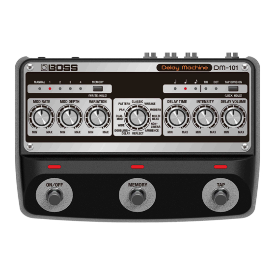
Panel Descriptions Panel Descriptions Top Panel Name Function Switches between or saves memories (MANUAL, 1–4). [MEMORY] button Indicates the currently selected memory. MEMORY When MIDI is used to select memories 5–127, all indicators go dark. indicators * If you turn the [VARIATION] knob while the mode is MULTI-HEAD, MEMORY indicators 1–4 indicate the head pattern you selected. - Page 4 Panel Descriptions Name Function Dotted quarter note (150%) µ µ Half-note triplet (133%) µ µ Quarter note (100%) µ Dotted eighth note (75%) µ µ Quarter-note triplet (67%) µ µ Eighth note (50%) µ Eighth-note triplet (33%) µ µ * Not supported in some delay modes. For details, refer to “1.5.
-
Page 5: Rear Panel
Panel Descriptions Rear Panel Name Function INPUT jack Connect your electric guitar, keyboard, or other musical instruments and effect units to this input jack. Connect your guitar amp, keyboard amp, other effect units or your mixer here. OUTPUT A/MONO, B For mono output, connect to the A/MONO jack. -
Page 6: Connecting External Pedals
Panel Descriptions Connecting External Pedals... -
Page 7: Turning The Power On/Off
Panel Descriptions Turning the Power On/Off Once everything is properly connected, be sure to follow the procedure below to turn on their power. If you turn on equipment in the wrong order, you risk causing malfunction or equipment failure. * Before turning the unit on/off, always be sure to turn the volume down. Even with the volume turned down, you might hear some sound when switching the unit on/off. -
Page 8: Mode List
MAX setting, VINTAGE Simulates the sound of the 10–300 ms µ the more complex the waveform becomes. BOSS DM-2. Produces a clear delay 40–840 ms MODERN µ sound with a distinct high end. - Page 9 Panel Descriptions (*1) You can switch between patterns 1–10 by changing the knob position. (*2) The contents of head patterns 1–10 are shown below. Head pattern Playback head 1 Á Á Á Á Á Á Á Playback head 2 Á Á...
-
Page 10: Saving And Switching Between Memories
Saving and Switching Between Memories Saving and Switching Between Memories Saving to a Memory You can save the settings you’ve edited. Long-press the [MEMORY] button. The indicator of the currently selected memory number blinks, and the memory enters write standby mode. Take your finger off the [MEMORY] button. -
Page 11: Various Settings
Various Settings Various Settings Setting the Expression Pedal Function By connecting an expression pedal (such as the EV-30, sold separately) to the CTL 1, 2/EXP jack, you can operate the top panel knobs except for the Mode knob. You can set the respective sounds for when the expression pedal is at MAX position (pushed all the way up with your toes) and at MIN position (pushed all the way down with your heel), and make continuous changes to them. -
Page 12: Setting The Footswitch Functions (Ctl 1 Function, Ctl 2 Function)
Various Settings Setting the Footswitch Functions (CTL 1 FUNCTION, CTL 2 FUNCTION) Here’s how to configure the functions of the footswitch connected to the CTL 1, 2/EXP jack (FS-5U, FS-6, FS-7; sold separately). Press and hold down the [TAP] switch, and turn on the power. Set the Mode knob to “CLASSIC”... -
Page 13: Switches Between Output Modes
Various Settings Switches Between Output Modes You can change how the output works by switching between output modes. You can turn the output of the direct sound off when you want to output only the effect’s sound, such as when you’re connecting this unit to the send/return of a mixer. -
Page 14: Preserving/Muting The Tail Of An Effect When The Effect Is Switched Off (Carryover)
Various Settings Preserving/Muting the Tail of an Effect when the Effect is Switched Off (CARRYOVER) This sets whether to preserve (carry over) the tail of an effect after the effect is switched off. Press and hold down the [TAP] switch, and turn on the power. Turn the Mode knob to the “MULTI-HEAD”... -
Page 15: Setting The Maximum Value Of Memory (Memory Extent)
Various Settings Setting the Maximum Value of MEMORY (MEMORY EXTENT) Here’s how to set the maximum value for the selectable memories. Press and hold down the [TAP] switch, and turn on the power. Turn the Mode knob to the “NON-LINEAR” setting. Use the [MEMORY] button to set the maximum value. -
Page 16: Midi Settings
Various Settings MIDI Settings Press and hold down the [ON/OFF] switch, and turn on the power. Turn the Mode knob to select the parameter to set. Use the [MEMORY] button to select the setting. Press the [ON/OFF] switch to exit the settings. Setting Mode knob Value... - Page 17 DM-101’s internal clock. MIDI clock sync (SYNC) AUTO MEMORY: 1 Operations are synchronized to the MIDI clock received via MIDI. However, operations are automatically synchronized to the DM-101’s internal clock if the unit is unable to receive the external clock.
- Page 18 Various Settings Transmit REALTIME DOUBLING+DELAY INTERNAL MEMORY: MANUAL Internal real-time messages are used as the clock source. SOURCE MIDI MEMORY: 1 Real-time messages from the MIDI IN connector are used as the clock source. MEMORY: MANUAL Specifies whether MIDI messages MIDI THRU WIDE received at the MIDI IN connector are...
-
Page 19: Restoring The Factory Default Settings (Factory Reset)
Restoring the Factory Default Settings (Factory Reset) Restoring the Factory Default Settings (Factory Reset) Press and hold down the [ON/OFF] switch and [TAP] switch, and turn on the power. Press the [TAP] switch. This starts the factory reset. The MEMORY indicators light up in this order: MANUALÓ1Ó2Ó3Ó4. The reset is finished once the [ON/OFF] switch lights up. -
Page 20: Attaching The Rubber Feet
Attaching the Rubber Feet Attaching the Rubber Feet You can attach the rubber feet (included) if necessary. Attach them in the locations shown in the illustration. * When turning the unit over, be careful so as to protect the buttons and knobs from damage. Also, handle the unit carefully; do not drop it. -
Page 21: Main Specifications
Main Specifications Main Specifications Memory 127 + Manual INPUT: -10 dBu Nominal Input Level INPUT: 1 MΩ Input Impedance OUTPUT A/MONO, OUTPUT B: -10 dBu Nominal Output Level Output Impedance OUTPUT A/MONO, OUTPUT B: 1 kΩ Recommended Load OUTPUT A/MONO, OUTPUT B: 10 kΩ or greater Impedance CLASSIC VINTAGE... - Page 22 Main Specifications DM-101 Reference Manual ©2023 Roland Corporation...
Need help?
Do you have a question about the DM-101 and is the answer not in the manual?
Questions and answers