Table of Contents
Advertisement
Quick Links
tel.:+370 319 60567 • fax:+370 319 60568 • e-mail: info@lak.lt • www.lak.lt
DOC. NO. LAK-17C-FES-AMM-00-00
It is a preliminary manual. The sailplane is not certified and has not shown compliance with
airworthiness requirements.
This sailplane is to be operated in compliance with the information and limitations contained
herein.
Joint Stock Company "SPORTIN ˙ E AVIACIJA ir Ko"
Poci¯ u nu ˛ km., Ašmintos sen., LT-59327, Prienu ˛ raj., Lithuania
TYPE: LAK-17
SERIAL NO.
REGISTRATION
DATE OF ISSUE
MAINTENANCE MANUAL
LAK-17C FES
with Front Electric Self-launcher system
MODEL: LAK-17C FES
TVIRTINU
UAB "Sportin˙ e aviacija ir Ko"
Direktorius
Powered Sailplane
Vytautas Mačiulis
Advertisement
Chapters
Table of Contents

Related Manuals for Sportine Aviacija LAK-17C FES


Summary of Contents for Sportine Aviacija LAK-17C FES
- Page 1 319 60567 • fax:+370 319 60568 • e-mail: info@lak.lt • www.lak.lt MAINTENANCE MANUAL DOC. NO. LAK-17C-FES-AMM-00-00 LAK-17C FES Powered Sailplane with Front Electric Self-launcher system TYPE: LAK-17 MODEL: LAK-17C FES SERIAL NO. REGISTRATION DATE OF ISSUE TVIRTINU UAB "Sportin˙ e aviacija ir Ko" Direktorius Vytautas Mačiulis...
- Page 2 LAK-17C FES Maintenance Manual Record of revisions Any revision of the present Manual, except actual weighing data, must be recorded in the following table and in case of approved Sections endorsed by responsible airworthiness authority. The new or amended text in the revised page will be indicated by black vertical line in the left hand margin, and the Revision No.
- Page 3 LAK-17C FES Maintenance Manual Revision Affected Affected Approval Date of Date of Signature Section Pages Approval Insertion Rev. 13/07/22 #0.1 ( ii )
- Page 4 LAK-17C FES Maintenance Manual List of Effective Pages Section Page Date of Issue Section Page Date of Issue 25 06 2020 25 06 2020 25 06 2020 25 06 2020 25 06 2020 25 06 2020 25 06 2020 25 06 2020...
- Page 5 LAK-17C FES Maintenance Manual Section Page Date of Issue Section Page Date of Issue 12-20-01 25 06 2020 53-00-01 25 06 2020 16-10-01 25 06 2020 53-00-02 25 06 2020 21-20-01 25 06 2020 53-10-01 25 06 2020 25-10-10 25 06 2020...
- Page 6 LAK-17C FES Maintenance Manual Section 1 GENERAL 1.1 Introduction ........
- Page 7 Maintenance Manual Introduction This Maintenance Manual contains information for pilots, technicians and mechanics about safe and proper maintenance of the sailplane LAK-17C FES. This information is given in accordance with requirements of CS 22.1529. Warnings, cautions and notes The following definitions apply to warnings, cautions and notes used in this manual:...
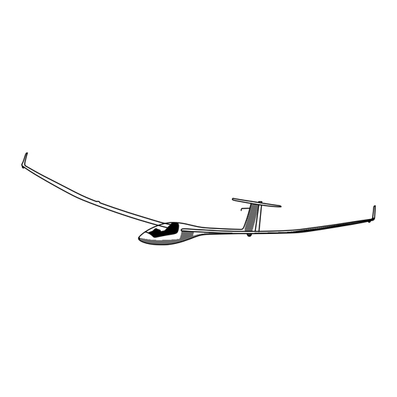
- Page 8 Maintenance Manual Technical data of the LAK-17C FES Wing span ........18 m (59.06 ft) Wing area .
- Page 9 LAK-17C FES Maintenance Manual Three-view drawing Rev. 25/06/20 #0.0...
-
Page 10: Table Of Contents
LAK-17C FES Maintenance Manual Section 2 DESCRIPTION OF THE SAILPLANE AND SYSTEMS 2.1 Introduction ........ - Page 11 LAK-17C FES Maintenance Manual 2.7.3 Allowed forces in control systems ..... . . 2-16 Rev. 25/06/20 #0.0...
-
Page 12: Introduction
LAK-17C FES Maintenance Manual Introduction In this section there is given description of sailplane aggregates, systems, equipment, tables and markings and information about proper sailplane maintenance. Airframe construction 2.2.1 Wing Sailplane wings (fig. 57-00-01, fig. 57-00-02) are made of composite materials and consist of four parts: right inner wing (pos. -
Page 13: Fuselage
LAK-17C FES Maintenance Manual 2.2.2 Fuselage The sailplane fuselage (fig. 53-00-01, fig. 53-00-02) is made of composite materials, construction is monocoque. The fuselage is oval-shaped in section (fig. 53-00-02), slightly narrowing at top and turning into circle at the fuselage end part. The fuselage end part is cone-shaped turning into fin. -
Page 14: Landing Gear
LAK-17C FES Maintenance Manual 2.2.5 Landing gear The landing gear consists of a retractable main wheel (fig. 32-30-01, pos. 5) and fixed tail wheel (fig. 53-00-01, pos. 6). Landing gear main wheel type TOST 045100 with Simplex shoe brake (or BERINGER wheel with brake) is attached to metal girder (fig. -
Page 15: Elevator Control System
LAK-17C FES Maintenance Manual 2.3.2 Elevator control system The elevator control system (fig. 27-30-01) consists of metal rods and bellcranks. In order to ensure rigidity the main rod in the fuselage is supported by guide rollers (pos. 5). Movement from the stick (pos. 1) by help of rods and intermediate bellcranks (pos. 2, 3, 4) is transmitted to the elevator and deflects it in required direction. -
Page 16: Airbrakes Control System
LAK-17C FES Maintenance Manual 2.3.5 Airbrakes control system The airbrakes control system (fig. 27-10-01, fig. 27-10-04, fig. 27-10-05) comprises the control handle (pos. 3), attached to the left side of a cockpit and rigid rods and bellcranks. Movement from control handle by help of an intermediate rod is transmitted to the shaft (pos. 8) which through an automatic joint transmits the movement to the shaft (pos. -
Page 17: Main Landing Gear Control System
LAK-17C FES Maintenance Manual 2.3.8 Main landing gear control system The landing gear control system (fig. 32-30-01) controls retracting and releasing of the main wheel. It consists of a control rod (pos. 1) on the right side of cockpit, an intermediate rod (pos. 2) and a bellcrank (pos. -
Page 18: Flight And Navigation Instruments
LAK-17C FES Maintenance Manual 3. Compensated pressure receiver (pos. 11) is a special Nix pipe mounted in fin. This line is marked by the letter N. 4. Flexible polyvinylchloride pipes of different colors transmit air pressure from receivers to corresponding measuring instruments on the sailplane instrument panel. Each separate pressure line has pipes of different colors:... - Page 19 Warning: Keep FCU instrument power supply always switched on during flight. Instrument indications. The FCU instrument for LAK-17C FES sailplane has on its front side three LED showing the most important states of the system during all operation time. Additional LCD display gives more detailed information about the same states and other values.
-
Page 20: Electric And Radio Equipment
FES battery box (fig. 72-00-00). LAK-17C FES two battery packs are wired in serial. One battery pack has 14 cells, so altogether 28 cells. Nominal capacity of each cell is 40 Ah, at middle voltage 3 7 V (minimum 3 2 V, maximum 4 2 V). -
Page 21: Canopy Ventilation System
LAK-17C FES Maintenance Manual • Always turn off FCU instrument and all other instruments (Flight computer, Caution: Flarm, Radio, Transponder, PDA), before removing Power fuse; • Always remove Power fuse before removing “+” or “–” supply cable; • Immediately put safety covers on battery terminals to avoid potential short circuit;... -
Page 22: Cockpit Equipment
LAK-17C FES Maintenance Manual The locking pin (fig. 52-10-01, pos. 13) must be removed before flight. Warning: 2.4.7 Cockpit equipment The cockpit equipment consist of: • safety belts, • a pilot seat, • a pocket of fabric (on the right side) for small things, documents. -
Page 23: Batteries
2.5.3 Batteries LAK-17C FES has two batteries packs wired in serial. One battery pack has 14 cells, so altogether 28 cells. Nominal capacity of each cell is 40 Ah, at middle voltage 3.7 V (minimum 3.2 V, maximum 4.2 V). - Page 24 LAK-17C FES Maintenance Manual Temperature indicator setting. • Long press “up” switch to set high temp value. Hold up and down switch at the same time to correction temperature. Set +90 °C temperature. • Long press “down” switch to set low temperature value. Hold up and down switch at the same time to correction temperature.
-
Page 25: Motor Controls
LAK-17C FES Maintenance Manual 2.5.4 Motor controls The LAK-17C FES motor is controlled by help of FCU (FES control unit) instrument. More detailed data about FES FCU instrument are described in separate “FES FCU Manual”, latest approved revision. 2.5.5 Propeller The propeller FES-LAK-P11-100 is shown at fig. - Page 26 LAK-17C FES Maintenance Manual Table 2.7.1-1 Connection Connected parts Max allowed gap (mm) Wing – fuselage Spars connection pin (pos. 1) – spar hub (pos. 2) 0.32 Wing – fuselage Fuselage lateral pin (pos. 3) – wing hub (pos. 4) 0.27...
- Page 27 LAK-17C FES Maintenance Manual Table 2.7.2-1 Pos. No. Measured motion Motion ∆ (mm) less than Stick, forward – backward Stick, left – right Edge of left aileron Edge of right aileron Edge of left flap Edge of right flap Edge of left elevator...
- Page 28 LAK-17C FES Maintenance Manual Section 3 SAILPLANE CURRENT MAINTENANCE 3.1 Sailplane current maintenance ......
-
Page 29: Sailplane Current Maintenance
LAK-17C FES Maintenance Manual Sailplane current maintenance 3.1.1 Daily inspection Note: Check the sailplane technical log-book and airworthiness certificate. The daily inspection must be performed each day and is essential for flight safety (refer to the fig. 16-10-01). 1. Check the sailplane fore part of fuselage;... -
Page 30: Post Flight Inspection
LAK-17C FES Maintenance Manual • deflections and clearances of controls, • fixing of joint of the stabilizer attachment to the fin, • clearance of the stabilizer with respect to the fin; 8. Check the right wing (analogically as for the left wing according to i.4);... -
Page 31: Storing And Transportation
LAK-17C FES Maintenance Manual 3.1.4 Storing and transportation During winter season or if a sailplane is not in use for a long time it is recommended to de-rig it. Sailplane metal surfaces of connection junctions shall be lubricated with oil. A sailplane shall be stored in a hangar or in a trailer. - Page 32 LAK-17C FES Maintenance Manual • fit the spar end of the right wing (pos. 4) into the fuselage window on the right side and push the wing along longitudinal axis so that the spar end of the right wing enters the fork of the left spar (pos.
-
Page 33: Lubrication System
LAK-17C FES Maintenance Manual • put on the stabilizer with an elevator so that protrudes on the elevator’s left and right sides (pos. 2) enter the recesses of control lever of the elevator (pos. 1) and the two hubs in spar of the stabilizer (pos. -
Page 34: Adjustment
LAK-17C FES Maintenance Manual 12. Main landing gear; 13. Tail wheel; 14. Propeller blades attachment point. When re-lubricating, clean old oil or grease before applying new. Adjustment 3.3.1 Adjustment of airbrakes If airbrake (fig. 27-60-10, pos. 1) extension occurs unexpectedly in flight it is necessary to tighten the springs of the lids (pos. -
Page 35: Adjustment Of Rudder Control System
LAK-17C FES Maintenance Manual 3.3.4 Adjustment of rudder control system Cables (fig. 27-20-01, fig. 27-20-02) are not adjustable. Adjustment of the rod (pos. 8). The rod is adjusted by turning of rod end. After adjustment make sure that the rod end doesn’t screw out of bounds of control opening. The end nut (pos. 12) shall be screwed up and fixed with spring washer (pos. -
Page 36: Rigging And Rigging Of A Flap
LAK-17C FES Maintenance Manual 3.4.2 De-rigging and rigging of a flap De-rigging of flap (see fig. 27-50-10): • loosen and remove the nut (pos. 6), • take off washer (pos 5), • pull the flap towards the end of wing until the hinge pins (pos. 3) are separated from wing. -
Page 37: Rigging And Rigging Of An Elevator
LAK-17C FES Maintenance Manual 3.4.4 De-rigging and rigging of an elevator 1. Operations used for de-rigging of an elevator (fig. 27-30-10): • take away wire split pins (pos. 3) and discard, • take away washers(pos. 2), • pull out hinge pins (pos. 1). -
Page 38: Removal And Installation Of Tail Wheel
LAK-17C FES Maintenance Manual • unscrew the bolt (pos. 2), • take out the washer (pos. 1), • disconnect the lever of wheel brake (pos. 3), • pull out the axle of wheel (pos. 4) together with hub (pos. 5, pos. 6) and washer (pos. 7), •... -
Page 39: Taking Out And Mounting Of Pilot Cockpit Floor
LAK-17C FES Maintenance Manual 3.4.10 Taking out and mounting of pilot cockpit floor The cockpit floor (fig. 25-10-10) consists of two removable parts: a stick hood (pos. 1) and a hood of cockpit bottom (pos. 2). Removal of the stick hood: •... - Page 40 LAK-17C FES Maintenance Manual To install the FES battery packs into the batteries box: 1. Open cover; 2. Check that Power switch is OFF; 3. Check that FCU instrument and all other instruments (Flight computer, Flarm, Radio, Transponder, PDA. . . ) are switched OFF;...
-
Page 41: Removing And Installing The Motor
LAK-17C FES Maintenance Manual To install the dummy boxes into the batteries box: 1. Open cover; 2. Insert first box into the fuselage and slide it back to rear position; 3. Insert second box into the fuselage and slide it to the first one;... -
Page 42: Mounting And Removal Of The Propeller
LAK-17C FES Maintenance Manual • Spinner is in the center of fuselage; • Gap between spinner and fuselage is 0 5 1 0 mm; • All bolted connections assembled correctly and secured; • Start the motor on a ground and run it for a few minutes to check: –... - Page 43 LAK-17C FES Maintenance Manual Section 4 MAINTENANCE OF THE SAILPLANE INSTRUMENTS AND EQUIPMENT ACCORDING TO THEIR OWN MAINTENANCE DOCUMENTS 4.1 Introduction ........
- Page 44 LAK-17C FES Maintenance Manual Introduction Here in this section is given the list of the sailplane instruments and equipment which service shall be done according to their own maintenance documents. Their servicing and repair shall be done independently of the sailplane maintenance requirements in Section 5.
- Page 45 LAK-17C FES Maintenance Manual (continued) No. Part Type Document Tail wheel Barum Rubena T3 / V12s Maintenance manual or TOST 200 Motor FES-LAK-M100 FES motor manual Propeller FES-LAK-P11-100 FES propeller FES-LAK-P11-100 manual Battery charger KOP1001 BMS version, or FES Battery pack manual...
- Page 46 LAK-17C FES Maintenance Manual Section 5 PERIODICAL INSPECTIONS 5.1 Introduction ........
- Page 47 LAK-17C FES Maintenance Manual Introduction In section 5 there is defined a list of inspections to ensure safe sailplane operation during its lifetime. The periodical inspections shall be performed by qualified staff authorized to perform the work. All inspections are general visual inspections unless specified otherwise.
- Page 48 LAK-17C FES Maintenance Manual Inspection after every 100 flight hours Date ....Checking Conformity Signature Yes / No Wing inner, wing outer 15 m and 18 m, winglet...
- Page 49 LAK-17C FES Maintenance Manual Inspection after every 100 flight hours Date ....Checking Conformity Signature Yes / No 312 Rudder, its hinges, pins, control connections 313 Stabilizer and fuselage connection pins, bolts and bolt fixation...
- Page 50 LAK-17C FES Maintenance Manual Inspection after every 100 flight hours Date ....Checking Conformity Signature Yes / No 605 Tail wheel (pressure in wheel tire, cracks) Control systems 701 Elevator control system (movement, friction, clearances, fixings)
- Page 51 LAK-17C FES Maintenance Manual Inspection after every 100 flight hours Date ....Checking Conformity Signature Yes / No Placards and markings CG data FES instrument wiring and functioning...
- Page 52 LAK-17C FES Maintenance Manual Inspection after every 100 flight hours Date ....Checking Conformity Signature Yes / No 1014 Check functioning of the propeller positioning...
- Page 53 LAK-17C FES Maintenance Manual Recommendations for extended storage Before winter storage at the end of the flight season or before extended storage in a hangar or in a trailer: 1. Check for any technical bulletins that need to be implemented;...
- Page 54 LAK-17C FES Maintenance Manual 7. Measure play at the control stick upper part with an elevator and ailerons fixed. Allowed clearance is ∆ = 2 mm (refer to paragraph 2.7.2); 8. To measure clearance in attachment joint of the landing gear. Allowed clearance between an opening and axis is ∆...
- Page 55 LAK-17C FES Maintenance Manual • condition of attachment joint of the towing hook; 13. To check glass fiber reinforced plastics for cracks and splits around these metal parts and joints: • spar hubs, • hubs of wing root ribs, • connection joints of stabilizer and fuselage, •...
- Page 56 LAK-17C FES Maintenance Manual Figure 5.7-2: The elevator control unit Initial clean off of paint shall be done with 180- to 220-grit sandpaper, finishing with 320-grit or even finer. 16. To check external surfaces of galvanized coating of metal parts. Zones with damaged protective galvanized or paint coating, if they are not damaged by corrosion reducing strength, may be repaired.
- Page 57 LAK-17C FES Maintenance Manual Figure 5.7-3: The vertical tail spar Rev. 25/06/20 #0.0 5-12...
- Page 58 LAK-17C FES Maintenance Manual Figure 5.7-4: The elevator root rib Figure 5.7-5: The fuselage bulkhead Rev. 25/06/20 #0.0 5-13...
- Page 59 LAK-17C FES Maintenance Manual Section 6 THE SAILPLANE LIFE LIMITS Service life of the sailplane is 6000 flight hours. The following FES system parts have limited service life: • refer to the current release of the manual for each FES component for service life limits.
- Page 60 LAK-17C FES Maintenance Manual Section 7 WEIGHTS AND CENTER OF GRAVITY 7.1 Introduction ........
- Page 61 LAK-17C FES Maintenance Manual Introduction Information about weighing of the sailplane, definition of center of gravity after sailplane repair, repainting or mounting of additional instruments or equipment is given in this section. Position of center of gravity is defined by the distance from the leading edge of wing root section (datum) towards the sailplane tail.
- Page 62 LAK-17C FES Maintenance Manual Table 7.2-1 Pos. No Sailplane part Marking Weight, kg Right inner wing with controls w.in.r Left inner wing with controls w.in.l Fuselage with rudder Stabilizer with elevator Right outer wing w.out18m.r Left outer wing w.out18m.l Right winglet wl.r...
- Page 63 LAK-17C FES Maintenance Manual 8. To calculate C.G.: (a) C.G. of empty sailplane cgemp (b) C.G. of sailplane with a pilot 9. To check if position of C.G. is within an allowed range. If C.G. is outside the allowed boundaries position the sailplane C.G. shall be corrected by the help of lead ballast (fig.
- Page 64 LAK-17C FES Maintenance Manual Reaction is defined with plane of control chord positioned horizontally. Note: Approved boundaries for control weights and static moments: Control Approved boundaries Approved static of control weight, kg moment of control, kg mm 0 55 20 0...
- Page 65 LAK-17C FES Maintenance Manual The C.G. calculation table Component , kg , mm , kg mm Empty glider Pilot Battery in fin 4192 Battery in baggage compartment Water ballast in wings Water ballast in fin 4003 Instrument N1 in instrument panel...
- Page 66 LAK-17C FES Maintenance Manual Rev. 25/06/20 #0.0...
- Page 67 LAK-17C FES Maintenance Manual Section 8 REPAIR 8.1 Introduction ........
- Page 68 LAK-17C FES Maintenance Manual Introduction General requirements for repair of minor sailplane damage are given in this section. Repair of minor FES damages are described in separate FES maintenance manual. Main requirements for repair work 1. Repair work shall be performed only by qualified and authorized staff.
- Page 69 LAK-17C FES Maintenance Manual Table 8.3.2-1 Pos. No Repair damage Zone 1 Zone 2 An opening 100 mm 40 mm Crack (split) 200 mm 100 mm Damage of leading edge 100 mm – for ailerons, 40 mm – for fin, stabilizer flaps;...
- Page 70 LAK-17C FES Maintenance Manual Table 8.3.4-1 Type (Iterglass No) Weaving type Mass, g/m Cloth thickness, mm Manufacturer Glass fabric 90070 Plain Interglass AG 92110 Twill 2/2 0.18 Interglass AG 92125 Twill 2/2 0.35 Interglass AG Carbon fabric 98131 Twill 2/2...
- Page 71 LAK-17C FES Maintenance Manual The given mixing ratio of components must be observed as exactly as possible. More or less hardener will not speed up or slow down the reaction – just cause only partial hardening which will not be corrected any way. Mixture of resin and hardener must be stirred thoroughly until there is no cloudiness in a vessel.
- Page 72 LAK-17C FES Maintenance Manual Section 9 ILLUSTRATIONS Rev. 25/06/20 #0.0...
- Page 73 LAK-17C FES Maintenance Manual Rev. 25/06/20 #0.0 Figure 05-20-10...
- Page 74 LAK-17C FES Maintenance Manual Rev. 25/06/20 #0.0 Figure 05-20-11...
- Page 75 LAK-17C FES Maintenance Manual Rev. 25/06/20 #0.0 Figure 08-10-01...
- Page 76 LAK-17C FES Maintenance Manual Rev. 25/06/20 #0.0 Figure 08-10-02...
- Page 77 LAK-17C FES Maintenance Manual Rev. 25/06/20 #0.0 Figure 08-10-10...
- Page 78 LAK-17C FES Maintenance Manual Rev. 25/06/20 #0.0 Figure 08-10-11...
- Page 79 LAK-17C FES Maintenance Manual Rev. 25/06/20 #0.0 Figure 11-00-01...
- Page 80 LAK-17C FES Maintenance Manual Placards and marking of controls Rev. 25/06/20 #0.0 Figure 11-00-02...
- Page 81 LAK-17C FES Maintenance Manual Placards and marking of controls Rev. 25/06/20 #0.0 Figure 11-00-03...
- Page 82 LAK-17C FES Maintenance Manual Placards and marking of controls Rev. 25/06/20 #0.0 Figure 11-00-04...
- Page 83 LAK-17C FES Maintenance Manual Placards and marking of controls Rev. 25/06/20 #0.0 Figure 11-00-05...
- Page 84 LAK-17C FES Maintenance Manual Placards and marking of controls Rev. 25/06/20 #0.0 Figure 11-00-06...
- Page 85 LAK-17C FES Maintenance Manual Placards and marking of controls Rev. 25/06/20 #0.0 Figure 11-00-07...
- Page 86 LAK-17C FES Maintenance Manual Rev. 25/06/20 #0.0 Figure 12-20-01...
- Page 87 LAK-17C FES Maintenance Manual Rev. 25/06/20 #0.0 Figure 16-10-01...
- Page 88 LAK-17C FES Maintenance Manual Rev. 25/06/20 #0.0 Figure 21-20-01...
- Page 89 LAK-17C FES Maintenance Manual Rev. 25/06/20 #0.0 Figure 25-10-10...
- Page 90 LAK-17C FES Maintenance Manual Rev. 25/06/20 #0.0 Figure 26-10-01...
- Page 91 LAK-17C FES Maintenance Manual Rev. 25/06/20 #0.0 Figure 26-10-02...
- Page 92 LAK-17C FES Maintenance Manual Rev. 25/06/20 #0.0 Figure 27-10-01...
- Page 93 LAK-17C FES Maintenance Manual Rev. 25/06/20 #0.0 Figure 27-10-02...
- Page 94 LAK-17C FES Maintenance Manual Rev. 25/06/20 #0.0 Figure 27-10-03...
- Page 95 LAK-17C FES Maintenance Manual Rev. 25/06/20 #0.0 Figure 27-10-04...
- Page 96 LAK-17C FES Maintenance Manual Rev. 25/06/20 #0.0 Figure 27-10-05...
- Page 97 LAK-17C FES Maintenance Manual Rev. 25/06/20 #0.0 Figure 27-10-10...
- Page 98 LAK-17C FES Maintenance Manual Rev. 25/06/20 #0.0 Figure 27-10-11...
- Page 99 LAK-17C FES Maintenance Manual Rev. 25/06/20 #0.0 Figure 27-20-01...
- Page 100 LAK-17C FES Maintenance Manual Rev. 25/06/20 #0.0 Figure 27-20-02...
- Page 101 LAK-17C FES Maintenance Manual Rev. 25/06/20 #0.0 Figure 27-20-03...
- Page 102 LAK-17C FES Maintenance Manual Mounting of rudder Rev. 25/06/20 #0.0 Figure 27-20-10...
- Page 103 LAK-17C FES Maintenance Manual Mounting of rudder Rev. 25/06/20 #0.0 Figure 27-20-11...
- Page 104 LAK-17C FES Maintenance Manual Rev. 25/06/20 #0.0 Figure 27-30-01...
- Page 105 LAK-17C FES Maintenance Manual Rev. 25/06/20 #0.0 Figure 27-30-02...
- Page 106 LAK-17C FES Maintenance Manual Rev. 25/06/20 #0.0 Figure 27-30-10...
- Page 107 LAK-17C FES Maintenance Manual Rev. 25/06/20 #0.0 Figure 27-50-10...
- Page 108 LAK-17C FES Maintenance Manual Rev. 25/06/20 #0.0 Figure 27-60-10...
- Page 109 LAK-17C FES Maintenance Manual Rev. 25/06/20 #0.0 Figure 31-00-01...
- Page 110 LAK-17C FES Maintenance Manual Rev. 25/06/20 #0.0 Figure 32-10-02...
- Page 111 LAK-17C FES Maintenance Manual Rev. 25/06/20 #0.0 Figure 32-30-01...
- Page 112 LAK-17C FES Maintenance Manual Rev. 25/06/20 #0.0 Figure 32-40-02...
- Page 113 LAK-17C FES Maintenance Manual Rev. 25/06/20 #0.0 Figure 32-40-03...
- Page 114 LAK-17C FES Maintenance Manual Rev. 25/06/20 #0.0 Figure 32-40-10...
- Page 115 LAK-17C FES Maintenance Manual Tail wheel Rev. 25/06/20 #0.0 Figure 32-40-20...
- Page 116 LAK-17C FES Maintenance Manual Rev. 25/06/20 #0.0 Figure 34-00-01...
- Page 117 LAK-17C FES Maintenance Manual Rev. 25/06/20 #0.0 Figure 34-10-01...
- Page 118 LAK-17C FES Maintenance Manual Rev. 25/06/20 #0.0 Figure 39-10-01...
- Page 119 LAK-17C FES Maintenance Manual Rev. 25/06/20 #0.0 Figure 40-10-01...
- Page 120 LAK-17C FES Maintenance Manual Rev. 25/06/20 #0.0 Figure 40-10-02...
- Page 121 LAK-17C FES Maintenance Manual Rev. 25/06/20 #0.0 Figure 41-20-01...
- Page 122 LAK-17C FES Maintenance Manual Rev. 25/06/20 #0.0 Figure 41-20-02...
- Page 123 LAK-17C FES Maintenance Manual Rev. 25/06/20 #0.0 Figure 41-20-03...
- Page 124 LAK-17C FES Maintenance Manual Rev. 25/06/20 #0.0 Figure 41-20-04...
- Page 125 LAK-17C FES Maintenance Manual Repair zones of the sailplane Rev. 25/06/20 #0.0 Figure 51-70-01...
- Page 126 LAK-17C FES Maintenance Manual Repair zones of the sailplane Rev. 25/06/20 #0.0 Figure 51-70-02...
- Page 127 LAK-17C FES Maintenance Manual Repair zones of the sailplane Rev. 25/06/20 #0.0 Figure 51-70-03...
- Page 128 LAK-17C FES Maintenance Manual Typical repair of composite sandwich Rev. 25/06/20 #0.0 Figure 51-70-10...
- Page 129 LAK-17C FES Maintenance Manual Rev. 25/06/20 #0.0 Figure 52-10-01...
- Page 130 LAK-17C FES Maintenance Manual Rev. 25/06/20 #0.0 Figure 52-10-02...
- Page 131 LAK-17C FES Maintenance Manual Rev. 25/06/20 #0.0 Figure 52-10-03...
- Page 132 LAK-17C FES Maintenance Manual Rev. 25/06/20 #0.0 Figure 53-00-01...
- Page 133 LAK-17C FES Maintenance Manual Rev. 25/06/20 #0.0 Figure 53-00-02...
- Page 134 LAK-17C FES Maintenance Manual Rev. 25/06/20 #0.0 Figure 53-10-01...
- Page 135 LAK-17C FES Maintenance Manual Rev. 25/06/20 #0.0 Figure 55-30-01...
- Page 136 LAK-17C FES Maintenance Manual Rev. 25/06/20 #0.0 Figure 55-10-01...
- Page 137 LAK-17C FES Maintenance Manual Rev. 25/06/20 #0.0 Figure 55-10-10...
- Page 138 LAK-17C FES Maintenance Manual Rev. 25/06/20 #0.0 Figure 55-10-11...
- Page 139 LAK-17C FES Maintenance Manual Rev. 25/06/20 #0.0 Figure 57-00-01...
- Page 140 LAK-17C FES Maintenance Manual Rev. 25/06/20 #0.0 Figure 57-00-02...
- Page 141 LAK-17C FES Maintenance Manual Rev. 25/06/20 #0.0 Figure 57-00-03...
- Page 142 LAK-17C FES Maintenance Manual Rev. 25/06/20 #0.0 Figure 57-00-04...
- Page 143 LAK-17C FES Maintenance Manual Rev. 25/06/20 #0.0 Figure 57-80-01...
- Page 144 LAK-17C FES Maintenance Manual Rev. 25/06/20 #0.0 Figure 57-80-02...
- Page 145 LAK-17C FES Maintenance Manual Rev. 25/06/20 #0.0 Figure 57-80-03...
- Page 146 LAK-17C FES Maintenance Manual Rev. 25/06/20 #0.0 Figure 57-80-04...
- Page 147 LAK-17C FES Maintenance Manual Rev. 25/06/20 #0.0 Figure 57-80-05...
- Page 148 LAK-17C FES Maintenance Manual Rev. 25/06/20 #0.0 Figure 61-10-01...
- Page 149 LAK-17C FES Maintenance Manual Rev. 25/06/20 #0.0 Figure 72-00-00...
- Page 150 LAK-17C FES Maintenance Manual Rev. 25/06/20 #0.0 Figure 72-00-01...
- Page 151 LAK-17C FES Maintenance Manual Rev. 25/06/20 #0.0 Figure 72-97-01...
Need help?
Do you have a question about the LAK-17C FES and is the answer not in the manual?
Questions and answers