Table of Contents
Advertisement
Advertisement
Table of Contents

Subscribe to Our Youtube Channel
Related Manuals for Misonix sonastar SYSTEM-M200


Summary of Contents for Misonix sonastar SYSTEM-M200
- Page 1 FS-1000-RF...
-
Page 2: Table Of Contents
Instructions for Use SonaStar Ultrasonic Surgical Aspiration System TABLE OF CONTENTS Operating Safety Precautions ....................4 General ..........................4 Conventions: Warnings, Cautions, and Notes ............... 4 Safety: Recommendations for the Use of this Device ............4-12 Handling of Handpieces ..................... 13 Explosion and Fire Hazard .................... - Page 3 Instructions for Use SonaStar Ultrasonic Surgical Aspiration System Cleaning, Sterilization and Maintenance .................. 56 General Information ......................56 Cleaning Procedures ..................... 56-58 Sterilization ........................59-60 Service & Repair Information ..................... 60 Routine Maintenance ......................60 Periodic Maintenance ....................60-61 Fuse Replacement………………………………………………….……………………….. 61 Moving the Unit ........................
- Page 4 Instructions for Use SonaStar Ultrasonic Surgical Aspiration System Table of Figures Figure 1-1 SonaStar Ultrasonic Surgical Aspiration System Figure 2-1 Top View Dimensions Figure 3-1 SonaStar Ultrasonic Surgical Aspiration System Figure 3-2 Wireless Footswitch Figure 3-3 Wireless Footswitch with Integrated IR Receivers on Console Top and Left Figure 4-1 Top / Side View Features Figure 4-2...
-
Page 5: Operating Safety Precautions
SonaStar system must be thoroughly familiar with its safety requirements and operating procedures. Any improper use or adjustment of this device may invalidate the Misonix Service Warranty agreement. Please contact your authorized Misonix representative before attempting to use this device in any manner other than those specified in this manual. - Page 6 Instructions for Use SonaStar Ultrasonic Surgical Aspiration System Warning Saline leakage through handpiece housing can cause a hazard when electrosurgery is energized. Always make sure the handpiece housing parts are properly assembled, with mating parts firmly in contact. Warning Never activate Vibration or electrosurgery while using the cleaning stylet. Tip damage and operator, patient, or staff injury may result.
- Page 7 Caution Improper use or adjustment of this device may invalidate the Misonix, LLC warranty agreement. Contact your authorized Misonix, LLC representative before attempting to troubleshoot this device in any manner other than those specified in this manual.
- Page 8 The SonaStar is configured for electrical input (line) at the factory before shipment, and is not intended to be configured or changed in the field except by Misonix, LLC authorized technical personnel. The unit may only be used with the electrical input originally intended.
- Page 9 Instructions for Use SonaStar Ultrasonic Surgical Aspiration System FCC Statement: This complies with FCC regulations for conducted and radiated emissions under FCC Part 18. UL Statement: This complies with UL Standard 2601-1 as well as IEC 60601-1. EMC Statement: The SonaStar system is designed and tested to comply with FCC regulations for conducted and radiated emissions under Part 18 Subchapter J.
- Page 10 Instructions for Use SonaStar Ultrasonic Surgical Aspiration System Guidance and Manufacturer’s Declaration – Electromagnetic Immunity (Table 204) Ultrasonic surgical suction system Expected to use in the following electromagnetic environment, buyers or users should ensure that it uses in the electromagnetic environment: Electromagnetic environment —...
- Page 11 Instructions for Use SonaStar Ultrasonic Surgical Aspiration System Environmental Protection Recommended Separation Distances Between Portable and Mobile RF Communications Equipment and the SonaStar Ultrasonic Surgical Aspirator (Table 206) The SonaStar Ultrasonic Surgical Aspirator is intended for use in an electromagnetic environment in which radiated RF disturbances are controlled.
- Page 12 Trademark Information ® ® Misonix and SonaStar are registered trademarks of Misonix, LLC Farmingdale, NY. ForceFX , Force 2 and Valleylab are trademarks of Valleylab, Boulder, CO. ConMed System 2400™ and System 2700™ are trademarks of ConMed Corporation, Utica, NY.
-
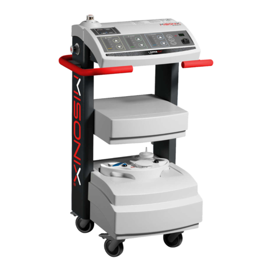
Page 13: Figure 1-1 Sonastar Ultrasonic Surgical Aspiration System
Instructions for Use SonaStar Ultrasonic Surgical Aspiration System Figure 1-1: SonaStar Ultrasonic Surgical Aspiration System IFU-601 Rev T March 2023 Page 12 of 73... -
Page 14: Handling Of Handpieces
To avoid injury, the unit should not be operated before ensuring that all its panels are properly closed. Do not attempt to remove or disassemble any panels or covers. Only Misonix, LLC authorized technical personnel should service the unit. -
Page 15: Using The Proper Fuse
Instructions for Use SonaStar Ultrasonic Surgical Aspiration System Using the Proper Fuse Caution The only fuses that may be replaced by hospital technical staff are the three fuses on the rear of the unit. Replacement fuses must be identical in type, voltage rating and current rating to the original fuse. - Page 16 Instructions for Use SonaStar Ultrasonic Surgical Aspiration System Handpiece Handpiece Vacuum Irrigation Curved Extended Linear Mode Handpiece Short Straight Elapsed Time Handpiece System Fault Preset Mode Handpiece Tip Setup Vibration Handpiece Handpiece Remove Probe Remove This Side Faces This Side Tighten Probe Do Not Reuse Torque...
- Page 17 Do Not Use If Upper Limit Packaging is Temperature Damaged For Use By R ONLY Product is LATEX Prescription Latex-Free Only Use with hard Misonix CE OSTEOSCULPT tissue removal Number 0482 accessories Signal Replace wireless transmission, footswitch Footswitch batteries activated...
- Page 18 Instructions for Use SonaStar Ultrasonic Surgical Aspiration System Vibration + Vibration Coagulation Flush Irrigation Coagulation Discard in Environmentally Remote IR Responsible Receiver Manner Hospital Grade Reusable. Plug Do Not Discard Do not Non-sterile resterilize medical device Single sterile barrier system Date of with protective Manufacture...
-
Page 19: Installation
Instructions for Use SonaStar Ultrasonic Surgical Aspiration System CHAPTER 2 INSTALLATION Space Requirements The width and depth dimensions for the SonaStar are shown in Figure 2-1. For enhanced accessibility to the SonaStar and convenience to the user, an open space, enough for a person to walk around, is required. -
Page 20: Electrical Requirements
The SonaStar is configured for a specific electrical input (line) at the factory before shipment, and is not intended to be configured or changed in the field except by Misonix authorized technical personnel. The unit may only be used with the electrical input originally intended. -
Page 21: System Description
Instructions for Use SonaStar Ultrasonic Surgical Aspiration System CHAPTER 3 SYSTEM DESCRIPTION Indications for Use The SonaStar Ultrasonic Aspirator System is indicated for use in the fragmentation, emulsification and aspiration of both soft and hard (i.e. bone) tissue in the following surgical specialties: ... -
Page 22: System Overview
Instructions for Use SonaStar Ultrasonic Surgical Aspiration System collapse of vapor pockets around cells in tissues having high water content. The collapse of the vapor pockets formed in such tissues results in tissue rupture. System Overview The SonaStar Ultrasonic Aspirator consists of a microprocessor-based control system and a handpiece, providing precise surgical tissue removal. -
Page 23: Figure 3-1 Sonastar Ultrasonic Surgical Aspiration System
Instructions for Use SonaStar Ultrasonic Surgical Aspiration System Figure 3-1: SonaStar Ultrasonic Surgical Aspiration System IFU-601 Rev T March 2023 Page 22 of 73... -
Page 24: Vibration System
Instructions for Use SonaStar Ultrasonic Surgical Aspiration System Vibration System Tissue fragmentation is achieved upon contact with the vibrating handpiece tip. The high frequency oscillation of the tip is powered by an ultrasonic generator within the console, which provides current to a piezoelectric transducer housed within the handpiece. -
Page 25: 3.7 Aspiration System
Instructions for Use SonaStar Ultrasonic Surgical Aspiration System 3.7 Aspiration System Irrigation fluid and fragmented tissue particles are continuously aspirated through the hollow titanium tip and the aspiration canal of the handpiece and are suctioned through the disposable tubing to a collection canister provided by the hospital. -
Page 26: Figure 3-3 Wireless Footswitch With Integrated Ir Receivers On Console Top And Left
Instructions for Use SonaStar Ultrasonic Surgical Aspiration System The wireless footswitch enables the operator to activate and control the system functions remotely without physically connecting a cable to the generator. The footswitch functions are: VIBRATION, VIBRATION+COAG, COAG, and FLUSH. Four coded Wireless frequencies are available to independently allow use of multiple systems in the same transmitting distance. -
Page 27: Controls, Indicators And Connections
Instructions for Use SonaStar Ultrasonic Surgical Aspiration System CHAPTER 4 CONTROLS, INDICATORS AND CONNECTIONS This chapter describes in detail the controls, indicators and connection points for the SonaStar Ultrasonic Surgical Aspiration System. Color coding has been used to simplify control of the three functional subsystems within the SonaStar System. -
Page 28: Figure 4-2 Lower Rear View
Instructions for Use SonaStar Ultrasonic Surgical Aspiration System 2. Irrigation Pump - peristaltic pump used to control flow of irrigating solution to the handpiece tip. The irrigation tubing is connected to the IV tubing, and routed clockwise around the pump, and to the handpiece. -
Page 29: Front Panel
Instructions for Use SonaStar Ultrasonic Surgical Aspiration System Front Panel IFU-601 Rev T March 2023 Page 28 of 73... - Page 30 Instructions for Use SonaStar Ultrasonic Surgical Aspiration System During operation, the display bars illuminate up to the actual aspiration load. The actual aspiration load is dependent on how much restriction is present in the line or at the tip. So for full open lines and tip, the aspiration may fluctuate at around 20 during vibration even though the preset is 100.
-
Page 31: Figure 4-4 Remote Ir Receiver
Instructions for Use SonaStar Ultrasonic Surgical Aspiration System Digital Display Time/Fault two-digit LED display. Provides indication of the accumulated time in whole minutes for which the vibration has been operating (vibration footswitch has been depressed). The time resets when the system’s power switch is turned off and on again. This readout also displays an error code (i.e., ‘E2’) in the event of a fault condition. -
Page 32: Components Rear View: Controls & Indicators
Instructions for Use SonaStar Ultrasonic Surgical Aspiration System 4.3. Components Rear View; Controls & Indicators The controls, indicators and connection points of the SonaStar are listed below and shown in Figures 4-5 and 4-6. Figure 4-5: Rear View Features Figure 4-6: Lower Rear View Details IFU-601 Rev T March 2023 Page 31 of 73... - Page 33 Power Cord Receptacle. Fuses - F1 and F2 (see Section 10.3 for replacement). 10. Fans 11. Electrosurgery Umbilical Connector – provides for connection to a Misonix-approved electrosurgical unit. See Chapter 7. 12. Footswitch Storage Shelf 13. Rating Plate - with Serial Number 14.
-
Page 34: Wireless Indicators
Instructions for Use SonaStar Ultrasonic Surgical Aspiration System Wireless Indicators 1. LED Indicator “Replace Footswitch Battery” (Solid red) 2. LED Indicator “Footswitch Activation” (Blinking blue) Wireless footswitch “Low Battery” and “Signal transmission" LED indicators Figure 4-7: Low Battery and Footswitch Activation LED(S) Receptacle for cable of Remote IR Receiver... -
Page 35: Figure 4-9 Wireless Footswitch
Instructions for Use SonaStar Ultrasonic Surgical Aspiration System Transmitter Footswitch Flush- Coagulation Dome Code Irrigation Vibration Only Vibration+Coagulation Identifier Only Figure 4-9: Wireless Footswitch Wireless Footswitch and (2) Dome Receivers all have matching labels ending in either 0, 1, 2 or 3 to indicate frequency Figure 4-10: Matching Wireless Footswitch and IR Receiver frequency Codes IFU-601 Rev T... -
Page 36: Handpieces
Instructions for Use SonaStar Ultrasonic Surgical Aspiration System CHAPTER 5 HANDPIECES General This chapter contains information on handpiece types, handpiece assembly, and handpiece testing for the SonaStar. One procedural pack, which includes a titanium tip, irrigation/aspiration tubing, silicone sleeve, O-rings and wire stylet is required to be sterile for the procedure. -
Page 37: Handpiece Assembly
Irrigation port for front housing (Short Straight handpiece only) Silicone sleeve/tip or Rigid sleeve There are a variety of ultrasonic tips available for the SonaStar System. Please ask your Misonix representative for the latest catalog of available tips. Ultrasonic tips are supplied sterile and for single use only. -
Page 38: Figure 5-2 Placing Ss & Ce Handpieces In The Counter Wrench
Instructions for Use SonaStar Ultrasonic Surgical Aspiration System 5.3.3 Installing the Tip 1. Examine the handpiece to make sure it is clean and the surface is free from nicks or damage. Note Inspect the output end of the handpiece where the probe is attached. Make sure this surface is clean and has no scratches or marks. -
Page 39: Figure 5-3 Exploded View Of Ce Handpiece Parts
Instructions for Use SonaStar Ultrasonic Surgical Aspiration System 5.3.4 Housing Assembly, Curved Extended Handpiece (CE) Remove the handpiece from the fixture. Install the Mid-Housing by screwing onto the handpiece. Then snap the silicone elbow onto the Mid-Housing and align with the notch in the silicone elbow. -
Page 40: Figure 5-5A Exploded View Of Ss Handpiece Parts
Instructions for Use SonaStar Ultrasonic Surgical Aspiration System Figure 5-5a: Exploded View of SS Handpiece Parts 1: Handpiece 3: Short Front Housing (CFSM6-H185) 2: Short Probe 4: Silicone sleeve Figure 5-5b: Exploded View of SS Handpiece Parts with Long Curved Plus Probe 1: Handpiece 3: Short Front Housing (CFSM6-H185) 2: Long Curved Plus Probe... -
Page 41: Electrosurgery Connector Assembly
Instructions for Use SonaStar Ultrasonic Surgical Aspiration System Electrosurgery Connector Assembly 1. The electrosurgery connector is located on the rear cap of the handpiece, adjacent to the cable strain relief. 2. For electrosurgery capability, plug the appropriate end of the Single-Use Monopolar Handpiece Cable into the handpiece end, as shown in Figure 5-6. -
Page 42: System Operating Instructions
Instructions for Use SonaStar Ultrasonic Surgical Aspiration System CHAPTER 6 SYSTEM OPERATING INSTRUCTIONS This chapter contains detailed operating instructions for the SonaStar Ultrasonic Aspirator. Pre-operative preparation, system setup, use during surgery, and post-operative storage are discussed. Preparation and use of the handpieces are discussed in Chapter 5. Pre-Operative Preparation Note The SonaStar system should be fully tested and inspected prior to each procedure. -
Page 43: Handpiece Preparation
Instructions for Use SonaStar Ultrasonic Surgical Aspiration System Handpiece Preparation Warning The handpiece and cable should be carefully inspected for cuts, cracks, or other signs of damage before each use. Any damaged equipment should be returned to your sales representative or dealer for repair or replacement. Warning Do not lay the handpiece on the patient when not in use. - Page 44 Instructions for Use SonaStar Ultrasonic Surgical Aspiration System 6.2.2 Method 2: Assembly in the sterile field. Tip: The handpiece, procedure pack, torque wrench and counter wrench should be sterilized prior to the following steps. Warning Use only sterilization cycles specified in this user manual. Do not use any other sterilization cycles.
-
Page 45: Preparing The Sonastar For Use
Instructions for Use SonaStar Ultrasonic Surgical Aspiration System Preparing the SonaStar for Use: 1. Connect the IV administration set to the last segment of the yellow striped irrigation tubing. Be sure to leave protective cap on the end of the IV spike. 2. -
Page 46: Figure 6-1 Open Irrigation Pump Gate
Instructions for Use SonaStar Ultrasonic Surgical Aspiration System Press Here to Open Figure 6-1: Open Irrigation Pump Gate 9. Pull taut the large diameter portion of the silicone irrigation tubing (with yellow stripe) that attaches to the IV line. Route clockwise around the irrigation pump head (see Figure 6-2), following the direction indicated with the IV spike at the top. -
Page 47: System Setup
Instructions for Use SonaStar Ultrasonic Surgical Aspiration System Warning Inadvertent or improper foot pedal depression can cause possible injury to the patient, surgeon, or operating room staff, and can cause product damage. Place foot pedal where it is highly visible, and labels can be clearly seen. If required, connect the remote IR receiver cable to the corresponding receptacle at the console rear. - Page 48 Instructions for Use SonaStar Ultrasonic Surgical Aspiration System 5. Press the Setup key again to initiate aspiration and irrigation system testing. During this check, the aspiration and irrigation displays will ramp up to 100% and back down to 0%. Once these tests reach completion the system will automatically flush the irrigation tubing by running the irrigation pump at maximum speed.
-
Page 49: Operative Use
Instructions for Use SonaStar Ultrasonic Surgical Aspiration System Operative Use For operative use involving electrosurgery, refer to Chapter 7. Caution Simultaneous use of a standard monopolar device with ultrasound can create sparking and possible tip damage. Caution Vibrating tip contact with hard objects can cause tip damage. Once system setup has been completed, the SonaStar is ready for use by the surgeon. - Page 50 Instructions for Use SonaStar Ultrasonic Surgical Aspiration System solution until all the solution has been aspirated. This process removes residual blood and tissue fragments from inside the tip and handpiece. This step is unnecessary if bone shaving was performed. 2. Turn off the unit by pressing the power OFF switch. Remove the handpiece from the sterile field. Disconnect the Remote IR receiver.
-
Page 51: Monopolar Coag Guidelines
Caution COAG should not be used in conjunction with bone shaving. The SonaStar system is designed to accommodate approved electrosurgical units. Check with your Misonix distributor for a complete list. Although these electrosurgery units support bipolar and monopolar instruments, as well as CUT and COAG modes, the SonaStar is designed for use in monopolar COAG mode only. CUT mode has been disabled for use with the system. -
Page 52: Figure 7-2 Monopolar Coag Interface Schematic
Item 2 Reusable Umbilical Connector, Erbe CFSM6-C142 Item 2 Reusable Umbilical connectors for other electrosurgery units Check with your Misonix distributor Single-Use Monopolar Handpiece Cable, 5-pack CFSM6-D050 Item 5 Disposable Table 7-1: Monopolar COAG Interface Components 5. Single-Use Monopolar Handpiece Cable 4. -
Page 53: Preparing The System For Monopolar Coag Use
® Instructions for Use SonaStar Ultrasonic Surgical Aspiration System Preparing the System for Monopolar COAG Use Consult the user manual supplied with the electrosurgery unit for operating instructions, safety guidelines, and setup. To enable monopolar COAG through the handpiece, perform the following steps (Refer to Figure 7-2): 1. -
Page 54: Figure 7-4 Monopolar Handpiece Cable Attached To Endcap Receptacle
® Instructions for Use SonaStar Ultrasonic Surgical Aspiration System Figure 7-4: Monopolar Handpiece Cable Attached to Endcap Receptacle 4. Plug the other end of the Single-Use Monopolar Handpiece Cable into the appropriate 4mm Monopolar receptacle on the electrosurgical generator as per manufacturer’s instructions. See figure 7-5 (other units connect in a similar manner). -
Page 55: Using Monopolar Coag With The System
VIBRATION + COAG pedal on the right-hand side of the footswitch may be depressed for simultaneous operation. 2. Misonix recommends staying within the limits prescribed by the electrosurgical generator’s user manual for the type of procedure being performed, up to a maximum of 70. Generally, the lowest setting that proves effective for the procedure being performed should be used. - Page 56 ® Instructions for Use SonaStar Ultrasonic Surgical Aspiration System 4. During electrosurgery use, the needle may develop eschar buildup. To maximize efficiency, the tip should be wiped clean with a sterile pad and alcohol. Briefly activating vibration with the tip immersed in sterile physiological saline will also clean the tip and flush the vacuum system lines.
-
Page 57: Cleaning, Sterilization And Maintenance
This chapter contains the cleaning, sterilization and maintenance information for the Ultrasonic Aspirator. Routine maintenance may be performed by qualified hospital personnel, unless otherwise stated. Any system maintenance not mentioned in this chapter should be performed by Misonix, LLC authorized technical personnel. - Page 58 ® Instructions for Use SonaStar Ultrasonic Surgical Aspiration System Inspect wrenches and remove any item which shows signs of damage (cracks, gouges, fractures Inspect etc.). Mark damaged items clearly to prevent future use before disposal. Inspect all items for cleanliness and damage following cleaning and prior to terminal sterilization. Post-Cleaning Table 8.1 Cleaning of wrenches Handpiece, Front Housing and CE Rigid Front Sleeve and Silicone Connector*...
- Page 59 Table 2.3 Cleaning of Handpiece, Front Housing, Wrenches and (Rigid Front Sleeve and Silicone Connector) 8.2.3 Cleaning of the console, footswitch and IR receiver Misonix recommends the use of CaviWipes1™ or equivalent surface disinfectant wipes. Please follow the manufacturer’s instructions for surface cleaning and disinfection including without limitation, the use of Personal Protection Equipment (PPE) for bloodborne pathogens.
-
Page 60: Sterilization
8.3.2. Sterilization of Reusable Sterile Field Components Warning: Use only sterilization cycles specified in this User Manual or on the Misonix website, www.misonix.com/sonastar/. Do not use any other sterilization cycles. Improper sterilization can lead to handpiece or accessory damage, patient injury, or death. -
Page 61: Service & Repair Information
If the Ultrasonic Aspirator and/or its accessories require repair or maintenance, contact your distributor, an authorized Misonix, LLC representative or Misonix at (800) 694-9612. Identify the unit by the serial number marked on the identification label on the rear panel. -
Page 62: 8.7 Fuse Replacement
Warranty Information Misonix LLC warrants each product manufactured by it to be free from defects in material and workmanship. Please refer to the Misonix LLC SonaStar Warranty Policy for full details. -
Page 63: Troubleshooting
In either case, the Fault status indicator will continue to flash until the system is powered- down and restarted. 3. Press the Preset or Linear key to resume operation in the desired mode. 4. When the operation is completed, be sure to call your Misonix, LLC Customer Service Department. IFU-601 Rev T... - Page 64 Ascertain that “tissue release” valve functions (opens and closes) properly during system test. Check that silicone section of tubing is inserted. Canister overflow (hydrophobic filter clogged or blocked). Solenoid or pump Press Fault Override button on the rear panel. Contact your Misonix,LLC malfunction service representative. *****N/A Aspiration Display not See Page 31 for explanation of Aspiration Display function;...
- Page 65 Solution Check power outlet. System does not power on Check fuses Fl, F2 and F3 on rear panel. Contact your Misonix, LLC service representative. Check footswitch. Verify Footswitch Actuation LED indicator illuminates. If no illumination refer to Footswitch Actuation LED indicator section below.
-
Page 66: Specifications
® Instructions for Use SonaStar Ultrasonic Surgical Aspiration System CHAPTER 10 SPECIFICATIONS This chapter contains the specifications for the SonaStar, its accessories and disposable items. 10.1 SonaStar Ultrasonic Surgical Aspiration System Generator Physical Dimensions Height: 40" (102cm) Width: 25" (63.5cm) Depth: 19"... - Page 67 ® Instructions for Use SonaStar Ultrasonic Surgical Aspiration System Modes of Operation: Setup mode: System setup Standby mode: Irrigation & Aspiration active Linear mode: Linear Vibration, Irrigation & Aspiration active Preset mode: Preset Vibration, Irrigation & Aspiration active Suspend mode: Aspiration pump shuts down Vibration Frequency: 23 kHz Stroke maximum amplitude:...
- Page 68 ® Instructions for Use SonaStar Ultrasonic Surgical Aspiration System Power Requirements Line Voltages: 100/110/115/120 VAC, 50/60 Hz. 200/220/230/240 VAC, 50/60 Hz. Must be configured to customer requirements during assembly at factory. Current Draw: 4 Amps max at 100/110/115/120 VAC 2 Amps max at 200/220/230/240 VAC 10.2 Footswitch Wireless...
-
Page 69: Footswitch/Remote Ir Receiver
® Instructions for Use SonaStar Ultrasonic Surgical Aspiration System Remote IR Receiver Functions Redundant infrared receiver Certification IEC/UL 60601-1 2nd and 3rd Edition Safety EN60601-1-2: 2007 EMC EN60529 Degree of Protection IP68 Size 5.0 in diameter Weight 2.0 lbs. Cable Length 18 feet (5.5 m) Power Power is supplied by console through cable. -
Page 70: 10.3 Fuse Requirements
® Instructions for Use SonaStar Ultrasonic Surgical Aspiration System 10.3 Fuse Requirements 1 0 0 / 1 1 0 / 1 1 5 / 1 2 0 V A C S y s t e m s Fuse LITTLEFUSE Location on Rear Relevant Fuse Fuse Type... -
Page 71: 10.5 Accessories
® Instructions for Use SonaStar Ultrasonic Surgical Aspiration System 10.5 Accessories Handpieces: Piezoelectric transducer – 23kHz Autoclavable Handpiece Assembly Set Counter wrench and torque wrench Footswitch Vibration Control Flush Irrigation Control COAG Control COAG + Vibration Simultaneous Control Drip, water and oil-tight Remote IR receiver ... -
Page 72: 10.6 Important Notice
U.S.A. Any serious incident occurring in relation to the SonaStar System should be reported to Misonix, LLC (using the contact information listed above) and the competent authority of the Member State in which the user is established. By returning any material to Misonix, LLC the customer or the customer’s agent must... - Page 73 ® Instructions for Use SonaStar Ultrasonic Surgical Aspiration System +1.631.694.9555 Phone +1.631.694.3285 fax 1938 New Highway, Farmingdale, N.Y. 11735, U.S.A. MISONIX.COM │ NASDAQ SYMBOL. MSON IFU-601 Rev T March 2023 Page 72 of 73...
Need help?
Do you have a question about the sonastar SYSTEM-M200 and is the answer not in the manual?
Questions and answers