Table of Contents
Advertisement
Advertisement
Table of Contents

Subscribe to Our Youtube Channel
Related Manuals for Misonix SonicOne O.R.


Summary of Contents for Misonix SonicOne O.R.
- Page 1 Instructions For Use SonicOne O.R. Powered by Misonix...
-
Page 2: Table Of Contents
Table of Contents General Safety Statements ..........................3 Summary of Safety Notices: Warnings, Cautions and Notes ..............3 1.1. EMC Statement ............................3 1.2. Electrical Safety Statement ........................7 1.3. Environmental Statement ......................... 8 1.4. Summary Of Safety Notices ........................8 1.5. -
Page 3: General Safety Statements
If RF equpiment is in use monitor the SonicOne O.R. for proper function during procedure. CAUTION 1.4 The use of accessories, transducers and cables other than those specified or provided by Misonix may result in increased electromagnetic emissions or decreased electromagnetic immunity of the device and result in improper operation. - Page 4 Electromagnetic Compatibility Guidance (in accordance with UL/EN/IEC 60601-1) Guidance And Manufacturer’s Declaration – Electromagnetic Emissions (Table 201) The SonicOne O.R SYSTEM is intended for use in the electromagnetic environment specified below. The customer or the user of SonicOne O.R SYSTEM should ensure that it is used in such an environment. Emissions test Compliance Electromagnetic environment –...
- Page 5 Guidance And Manufacturer’s Declaration – Electromagnetic Immunity (Table 202) The SonicOne O.R SYSTEM is intended for use in the electromagnetic environment specified below. The customer or the user of the SonicOne O.R SYSTEM should assure that it is used in such an environment. IEC 60601 Immunity test Compliance level...
- Page 6 Guidance And Manufacturer’s Declaration – Electromagnetic Immunity (Table 204) The SonicOne O.R SYSTEM is intended for use in the electromagnetic environment specified below. The customer or the user of the SonicOne O.R SYSTEM should assure that it is used in such an environment. Immunity test IEC 60601 test level Compliance level...
-
Page 7: Electrical Safety Statement
Do not attempt to remove or disassemble the cover. There are no user-serviceable parts inside the console. All service should only be performed by an authorized Misonix representative. No modification of this equipment is required. -
Page 8: Environmental Statement
However, the user is advised to read the entire manual and operate the device only in accordance with all of the instructions contained herein. Servicing of this device should only be performed by qualified technicians authorized by Misonix, Inc. There are no service controls accessible to the user. - Page 9 To avoid injury, the console should never be operated before ensuring that its cover is properly closed and not tampered with. Do not attempt to remove or disassemble the cover. There are no user-serviceable parts inside the console. All service should only be performed by an authorized Misonix representative. No modification of this equipment is required.
- Page 10 WARNING 9.3 Misonix Inc. has validated all cleaning and sterilization cycles given in this manual. It is highly recommended that the procedures given in this manual for cleaning and sterilizing the SonicOne O.R system and related accessories be followed. It is the responsibility of the user of this device or any accessories used with it to validate procedures for cleaning and/or sterilization if they differ from the procedures as outlined in this manual.
- Page 11 CAUTION 12.1 Use only genuine replacement parts from Misonix. Use of parts furnished by other sources may result in patient or operator injury or system malfunction and will void any applicable warranty.
-
Page 12: Trademark Information
1.5. Trademark Information Misonix® and SonicOne® are registered trademarks of Misonix, Inc., Farmingdale, NY ASP Enzol® and Prolystica® are registered trademarks of STERIS Corporation, Mentor, OH E-SOUM-OR Rev M... -
Page 13: Explanation Of Symbols
AC Voltage Lot or batch code greater than indicated Must use hospital grade power cord Manufacturer Fuse only Misonix CE Footswitch Classified by UL number connector Irrigation Source Contains DEHP Vacuum source and/or Phthalates Table 1.6 Explanation of symbols... -
Page 14: Indications And Contra Indications
2. Indications And Contra Indications 2.1. Indications The SonicOne O.R® is indicated for use in debridement of wounds, such as, but not limited to burn wounds, diabetic ul- cers, bedsores and vaginal ulcers, soft tissue debridement and cleansing of the surgical site in application, in which, in the physician’s judgement would require the use of an ultrasonic aspirator with sharp debridement. -
Page 15: Considerations During Clinical Use
4. Considerations During Clinical Use WARNING 4.1 Contact to vibrating elements like extension and ultrasonic tip may cause burns and should be avoided by all means. The handpiece should only be held at the black housing area. An optional, protective silicone sleeve, included with certain tips, reduces the risk of thermal damage but does not eliminate it. - Page 16 Tip Limitations During Bone Removal Both the ultrasonic tip and the extension are vibrating at high frequency and are thus exposed to extreme mechanical stresses, especially when cutting bone. WARNING 4.2 Ultrasonic tips can break under excessive use in extreme conditions, e.g. when cutting for extended duration in tight cavities with limited lateral motion.
-
Page 17: System Overview
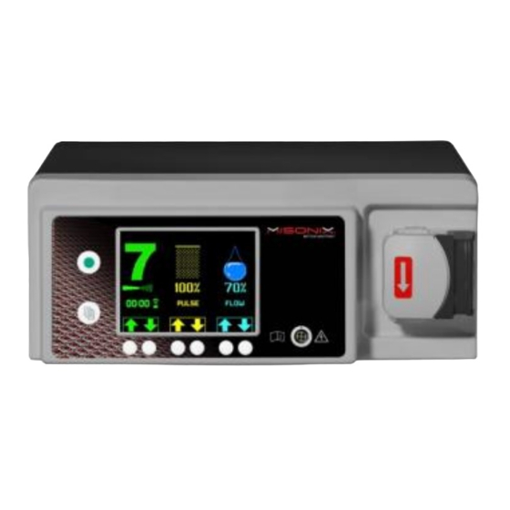
The console features an integrated irrigation pump. Figure 5.2 SonicOne O.R Handpiece Figure 5.1 Misonix Console The console produces an electrical signal that is fed into the handpiece and its piezoelectric transducer. The transducer converts the electrical signal into mechanical vibrations. The vibratory motion is amplified all the way down to the tip’s distal end. -
Page 18: Reusable System Components
Hard Tissue Probe Cover 1 ea. BCM-H2 Soft Tissue Probe Cover 1 ea. Table 5.2 Required system components Components and quantities included with the system may change over time, please check with your Misonix representative for the most current configuration. E-SOUM-OR Rev M... -
Page 19: Single Use, Sterile Components
Table 5.3 Irrigation tubeset There are a variety of ultrasonic tips available for the SonicOne O.R system. Please ask your Misonix representative for the latest catalog of available tips. Ultrasonic tips are supplied sterile and are for single use only. - Page 20 The front of the console features a receptacle for the handpiece cable and an irrigation pump head, in which the irrigation tubing is inserted. A large color LCD screen provides information on system status and set points for ultrasound amplitude, pulse rate and irrigant flow rate with respective controls on the panel below.
-
Page 21: Menu Functions
The handpiece receptacle is keyed in order to facilitate connection. The red dot on top of the receptacle must be in line with the corresponding red dot on the handpiece cable. 6.2. Menu Functions The standard screen is the Main Screen. Additional screens are the Options and the Help Screen. Both the Options and Help screens can be accessed by pressing the menu button to toggle through the three main screens;... - Page 22 Ultrasound Timer The ultrasound timer records the elapsed time, in which the ultrasound was activated with the footswitch. The timer can be re-set to zero via the secondary screen. In the event of error, such as a Mechanical Limit or an Electrical Fault, the main screen is replaced by alert screens. Refer to section 6.4 for a description of these warnings.
-
Page 23: Main Functions
Help Screen The Help Screen provides access to a quick guide on system operation and troubleshooting. Menu Button Software Revision A-F Custom buttons A B C D Figure 6.2.3 Help screen System Operation Press A to access the quick reference guide on system operation. Troubleshooting Press B to access the quick reference guide on troubleshooting. - Page 24 Pulse Setting 50-90% [Pulsed] The Pulse function minimizes exposure to ultrasound over time. The Pulse setting corresponds to the duration of the active period of the ultrasound output. For example, a Pulse setting of 60% corresponds to an active period of 60% of ¼ second (150ms). The resulting resting period is 40% of ¼ second (100ms). The ultrasonic energy output over time is reduced by 40% with this setting.
-
Page 25: Alerts And Indicators
Standby Mode Enable Mode Amplitude setting is GREY and HOLLOW Amplitude setting is GREEN and SOLID Footswitch activates Footswitch activates • Irrigation only. Irrigation can be used for lavage or • Ultrasound output and irrigation. A bell chime is emit- priming. - Page 26 Tip overload can occur during hard tissue removal when applying excessive tip pressure or facing strong tissue resistance, e.g. from thick cortical bone. This can lead to stalling of the ultrasonic tip. A pulsed audible signal alerts of the stalling and the ultrasound is deactivated.
-
Page 27: System Set-Up
7. System Set-up 7.1. Installation Upon delivery perform a visual inspection of the shipping containers and all system components for obvious shipping damage. Retain the shipping container and immediately notify the shipping carrier of any damages found. CAUTION 7.1 All reusable system components like handpiece, probe covers, counter wrench, and T-wrench are supplied industrially cleaned, but NON-STERILE. - Page 28 The console can be placed on an appropriate table or cart outside of the sterile field. Ensure that the pump head on the con- sole right is installed. Refer to section 12.2 if the pump head is not yet installed. Adjust the grip of the V-notches Evenly adjust the V-notches to their fully opened position by turning the adjust-...
-
Page 29: Console Set-Up - Part I (Non-Sterile)
7.2. Console Set-up – Part I (Non-sterile) Console Set-up | Part I Switch Mains Power OFF Set Mains Power switch on console rear to OFF. Connect IV-pole Connect IV-pole to receptacle in console rear. Hang container with sterile physiological saline irrigant into IV-pole hook. Irrigation tubing features IV-spike and is compatible with rigid bottles or flexible bags. -
Page 30: Console Set-Up - Part Ii (Non-Sterile)
7.4. Console Set-up – Part II (Non-sterile) Console Set-up | Part II Connect Handpiece cable Attach cable connector receptacle on console front panel. Align red dot on cable connector with red dot on front panel receptacle. Push cable connec- tor into place. Open the latch of the irrigation pump Open pump cover The arrow on the pump housing indicates the direction of flow. - Page 31 WARNING 7.1 Improper connection of the handpiece cable may present a shock hazard. Confirm that handpiece connector is dry prior to plugging it in. WARNING 7.2 Do not operate pump with pump cover in raised position. Rollers might pinch loose clothing or fingers. Personal injuries may result.
-
Page 32: Perform System Check
7.5. Perform System Check System Check Enable Ultrasound Switch to Enable Mode using enable/standby button. Confirm that Amplitude setting is FILLED GREEN. Depress footswitch Direct ultrasonic tip toward suitable reservoir to collect irrigant. Depress footswitch. Confirm Function Console emits a bell chime. Irrigant will be pumped from console towards handpiece. -
Page 33: Handpiece Disassembly
CAUTION 8.1 Ensure all connections and mating surfaces of handpiece, extension and ultrasonic tip are clean and dry before assembly. CAUTION 7.2 All items intended for use in the sterile field must be cleaned and sterilized as per indicated instructions before each clinical use. -
Page 34: Cleaning And Sterilization
9. Cleaning And Sterilization Follow manufacturers directions for preparing solutions. Misonix recommends the use of CaviWipes® or equivilent quarternary ammonium compound surface disinfectant wipe. Please follow manufacturers insturctions for surface cleaning and disinfection of hard non porous surfaces, including, without limitation, the use of personal Protection Equipment(PPE) for Bloodborne Pathogens. -
Page 35: Cleaning
WARNING 9.3 Misonix Inc. has validated all cleaning and sterilization cycles given in this manual. It is highly recommended that the procedures given in this manual for cleaning and sterilizing the SonicOne O.R System and related accessories be followed. - Page 36 Console and Footswitch Wipe Surfaces • Follow manufacturer’s directions for preparing solutions. Misonix recommends the use of CaviWipes1 ® or an equivalent quanternany ammonium compound surface cleaning and disinfection wipe. Wipe footswitch and console, including irrigation unit, with cloth or absorbent paper moistened with an enzymatic detergent such as ASP Enzol® or Steris Prolystica®.
- Page 37 9.2.2 Automated Wash Procedure Handpiece, Probe Cover and Wrenches Point of Use Immediately following procedure perform the following: • Flush handpiece lumen with minimum 100 mL of saline to clear the bore of debris. • Wipe all reusable devices to remove visible blood and debris. CAUTION: DO NOT use saline to wet the tray and tray contents before transport to the decontamination processing area.
-
Page 38: Sterilizing By Steam Autoclave
*Exposure time can be increased up to a maximum of 18 minutes to comply with local requirements and/or recommenda- tions of the World Health Organization (WHO), Robert Koch Institute (RKI), etc. Misonix Inc reusable medical devices are able to sustain such sterilization cycles. -
Page 39: Expected Life, Reusable Components
9.5 Deviations From Decontamination, Cleaning And Sterilization Instructions Misonix Inc. has validated all cleaning, disinfection and sterilization cycles given in this manual. It is highly recommended that the procedures given in this manual for cleaning and sterilizing the SonicOne O.R system and related accessories be followed. - Page 40 Corrective Action Possible Cause Release footswitch. Tip overload Reduce tip pressure and/or use higher amplitude setting as required. Continue procedure. Release footswitch. Set ultrasound to STANDBY. Remove silicone sleeve (if applicable) and probe cover. Loose or Inspect extension probe and ultrasonic tip for damage. Replace if necessary. damaged component Otherwise re-tighten extension probe and tip using the correct wrenches.
- Page 41 Do not operate pump with pump cover in raised position. Rollers might pinch loose clothing or fingers. Personal injuries may result. Cooling of the ultrasonic tip and irrigation at the treatment site will be inhibited. For all other malfunctions please contact Misonix or a Misonix authorized representative for service. E-SOUM-OR Rev M...
-
Page 42: Specifications
11. Specifications Console Specifications Power input (E-SOGEN-OR) • 120VAC, 4 Amps, 60Hz • 220/230/240 VAC, 2.5 Amps, 50/60 Hz Power input (E-SOGEN-OR-100V) • 100VAC, 6.3 Amps, 50/60Hz • 200 VAC, 3.15 Amps, 50/60Hz Operating frequency 22.5 kHz Ground leakage current 300 µA (max.) Output power 130 Watts (max.) -
Page 43: Service, Repair And Technical Correspondence
BCM-H2 Soft Tissue Probe Cover 2 ea. able 11.2 System contents Components and quantities included with the system may change over time, please check with your Misonix representative for the most current configuration. UL (IEC) 60601-1 Classification Class 1 Equioment... - Page 44 Model BCM-GN-100V Fuse Specifications Line Voltage Manufacturer Manufacturer P/N Rating Description Fast Acting, Low Break- 100 VAC, 50/60 Hz Cooper/Bussman GDB-6.3 250V @ 6.3 A Fast Acting, Low Break- 200 VAC, 50/60 Hz Cooper/Bussman GDB-3.15 250V @ 3.15 A Table 12.2 Console fuse specifications model Fuse Replacement (The fuse holder is located on the console rear) Switch to Standby Mode using enable/standby button.
-
Page 45: Pump Head Replacement
12.2 Pump Head Replacement The pump head may not be connected to the unit for shipping purposes. Mount Pump Head Shaft recess and bayonet fitting on Pump drive shaft on console front pump head rear Position Pump Head Align drive shaft on console front and shaft recess on pump head rear. -
Page 46: Repair, Service And Replacement Parts
12.3 Repair, Service and Replacement Parts All requests for repairs and replacement parts should be directed to Misonix or an authorized Misonix representative. Always provide model and serial number of malfunctioning items. When returning items include model, serial and RMA number as well as purchase order number on all documents. Always prepay return shipping and specify method of shipment. -
Page 47: Important Notice
U.S.A. By returning any material to Misonix, Inc. the customer or the customer’s agent must certify that any and all materials so returned are or have been rendered free of any hazardous or noxious matter or radioactive contamination and are safe for handling under normal repair shop conditions. - Page 48 +1.631.694.9555 phone +1.631.694.3285 FAX 1938 NEW HIGHWAY, FARMINGDALE, N.Y. 11735, U.S.A. MISONIX, INC. NASDAQ SYMBOL. MSON MISONIX.COM © 2017 Misonix, Inc. All rights reserved. Printed in the USA. E-SOUM-OR Rev M E-SOUM-OR Rev M...
Need help?
Do you have a question about the SonicOne O.R. and is the answer not in the manual?
Questions and answers