
Subscribe to Our Youtube Channel
Related Manuals for GHM Delta OHM HD2114P.0


Summary of Contents for GHM Delta OHM HD2114P.0
- Page 1 English Operating manual Manometers for Pitot tubes / thermometers HD2114P.0 – HD2114P.2 HD2134P.0 – HD2134P.2 Companies / Brands of GHM www.deltaohm.com Keep for future reference.
-
Page 2: Table Of Contents
CONTENTS INTRODUCTION ..............................3 KEYBOARD AND MENU DESCRIPTION ......................8 THE PROBES ................................14 ................................15 PERATION ..........................16 IMENSIONS OF ITOT TUBES ............................16 LOW RATE MEASUREMENT ..........................18 EMPERATURE MEASUREMENT WARNINGS AND OPERATING INSTRUCTIONS ....................20 INSTRUMENT SIGNALS AND FAULTS ......................21 LOW BATTERY WARNING AND BATTERY REPLACEMENT ...............23 INSTRUMENT STORAGE .............................24 SERIAL INTERFACE AND USB ...........................25 STORING AND TRANSFERRING DATA TO A PERSONAL COMPUTER ............27... -
Page 3: Introduction
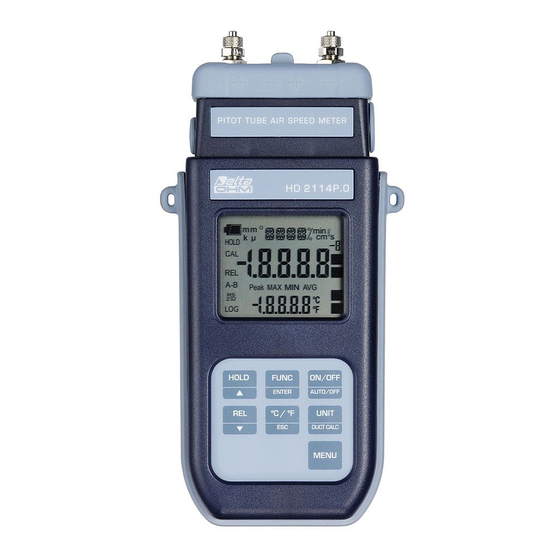
INTRODUCTION The HD2114P.0 and HD2114P.2, HD2134P.0 and HD2134P.2 are portable micromanometers using Pitot or Darcy tubes and a large LCD display. They are used to perform measurements in the fields of air conditioning, heating and ventilation. They measure the differential pressure detected by a Pitot or Darcy tube connected to the instrument inputs acquiring the wind speed and flow rate inside pipelines and vents. - Page 4 HD2114P.0 - HD2134P.0 Micromanometer with Pitot tube - Thermometer - 4 - HD2114P/HD2134P V2.3...
- Page 5 HD2114P.0 - HD2134P.0 1. Input for thermocouple K, standard miniature connector. 2. Positive input (+) into the pressure sensor. Quick coupling Ø 5mm 3. Battery symbol: displays the battery charge level. 4. Function indicators. 5. Secondary display line. 6. HOLD/ key: freezes the measurement during normal operation;...
- Page 6 HD2114P.2 - HD2134P.2 Micromanometer with Pitot tube - Thermometer - 6 - HD2114P/HD2134P V2.3...
- Page 7 HD2114P.2 - HD2134P.2 1. Input for thermocouple K, standard miniature connector. 2. Positive input (+) into the pressure sensor. Quick coupling Ø 5mm 3. External auxiliary power supply connector input (positive at centre). 4. Battery symbol: displays the battery charge level. 5.
-
Page 8: Keyboard And Menu Description
KEYBOARD AND MENU DESCRIPTION Foreword The instrument keyboard is composed of single-function keys, like the MENU key, and double- function keys such as the ON-OFF/Auto-OFF key. In the double-keys, the function in the upper part is the "main function", while the one in the bottom part is the "secondary function". - Page 9 FUNC/ENTER key During normal measurement this enables the display and logging of the maximum (MAX), minimum (MIN) and average (AVG) value of the measurements captured by the Pitot tube connected to the instrument, updating them with the acquisition of new samples. The acquisition frequency is once a second.
- Page 10 °C/°F - ESC key The measured temperature value is used to compensate the wind speed measurement. When the temperature probe is connected, the key changes the unit of measurement from degrees Celsius to Fahrenheit. If the probe is not present, the compensation temperature must be entered manually: to manually change the value shown in the display lower line, press °C/°F once.
- Page 11 Use the arrows and confirm with ENTER. Please see the paragraph dedicated to wind speed measurement on page 14. 4) Pres Baro (barometric pressure): the wind speed detected by the Pitot tube is the result of different factors. Among these is the atmospheric pressure resulting from the formula reported on page 15.
- Page 12 11) YEAR (only HD2114P.2 and HD2134P.2): to set the current year. Use the arrows to modify this parameter and confirm using ENTER. 12) MNTH (month) (only HD2114P.2 and HD2134P.2): to set the current month. Use the arrows to modify this parameter and confirm using ENTER. 13) DAY (only HD2114P.2 and HD2134P.2): to set the current day.
- Page 13 SERIAL/EraseLOG key - only HD2114P.2 and HD2134P.2 In measurement mode, this function starts and stops the data transfer to the serial output. According to the settings entered in the Print and log interval menu item, a single sample can be printed if Print and log interval=0 or a continuous indefinite printing of the measured data can be set up if Print and log interval=1…3600.
-
Page 14: The Probes
THE PROBES The HD2114P.0 and HD2114P.2 instruments are fitted with a 20mbar differential pressure sensor compared to an atmosphere, the HD2134P.0 and HD2134P.2 models have a 200mbar sensor. Any type of Pitot tube with relevant thermocouple K can be connected to the instruments to measure the incident wind speed and calculated flow rate. -
Page 15: Operation
The following relationship gives the wind speed: as you can see this is dependent on the three pressures and the air temperature. ⎡ ⎤ mbar 1000 100.000 • • • • • 1.291 ⎢ ⎥ ⎣ ⎦ [Pv] [Ps] 100.000 °... -
Page 16: Dimensions Of Pitot Tubes
The error reported in case of misalignment is reported in the following graph: +0.6 +0.4 +0.2 -0.2 -0.4 -0.6 -0.8 -1.0 -1.2 15° 10° 5° 5° 10° 15° ANGLE The abscissas reports the rotation angle around its vertical axis compared to the flow direction (yawing), in ordinates the % error on the differential pressure Pv measurement. - Page 17 To set the measurement in inch , select the "SECT m2" menu item, and using the UNIT key, change the unit of measurement from m to inch . Proceed to enter the data using the arrows: confirm with ENTER. The area inserted as above remains in the memory so the flow rate measurements can be repeated on other identical vents, without having to set the area again.
-
Page 18: Temperature Measurement
2) Moving average The Duct Calc function provides a spatial averaging of the captured values and therefore compensates the speed differences between one point and another in the duct section. There is also another source of errors due to the variation of the flow in time : that is, the flow is not constant but increases or decreases in the same point . - Page 19 In the temperature measurement by penetration the probe tip must be inserted to a depth of at least 60mm, the hot junction is housed in the end part of the probe. When measuring the temperature on frozen blocks it is convenient to use a mechanical tool to bore a cavity in which to insert the tip probe.
-
Page 20: Warnings And Operating Instructions
WARNINGS AND OPERATING INSTRUCTIONS 1. Do not expose the probes to gases or liquids that could corrode the material of the sensor or the probe itself. Clean the probe carefully after each measurement. The pressure sensor is suitable for measurement of only non corrosive dry gases or air and not liquid: check the membrane compatibility with the plant fluid. -
Page 21: Instrument Signals And Faults
INSTRUMENT SIGNALS AND FAULTS The following table lists all error indications and information displayed by the instrument and supplied to the user in different operating situations. Display indications Explanation This appears if the pressure sensor detects a value exceeding the limit of 125% of the bottom scale nominal value. - Page 22 The following table reports the indications provided by the instrument as they appear on the display, together with their description. Display indication Explanation >>>_LOG_DUMP_or_ERAS transfer or erase data 20 mBAR DIFF probe 20mbar differential 200 mBAR DIFF probe 200mbar differential moving average in seconds AVG TIME SECS BATT TOO LOW - CHNG NOW...
-
Page 23: Low Battery Warning And Battery Replacement
LOW BATTERY WARNING AND BATTERY REPLACEMENT The battery symbol on the display constantly shows the battery charge status. To the extent that batteries have discharged, the symbol "empties". When the charge decreases still further it starts blinking… In this case, batteries should be replaced as soon as possible. If you continue to use it, the instrument can no longer ensure correct measurement. -
Page 24: Instrument Storage
ALFUNCTIONING UPON TURNING ON AFTER BATTERY REPLACEMENT After replacing the batteries, the instrument may not restart correctly; in this case, repeat the operation. After disconnecting the batteries, wait a few minutes in order to allow circuit condensers to discharge completely; then reinsert the batteries. ARNING ABOUT BATTERY USE •... -
Page 25: Serial Interface And Usb
SERIAL INTERFACE AND USB The HD2114P.2 and HD2134P.2 instruments are fitted with an electrically isolated RS-232C serial interface, and an USB 2.0 interface. The following serial cables can be used: • HD2110CSNM : serial connection cable with 8-pole MiniDin connector on one end and 9-pole Sub D connector on the other end;... - Page 26 Command Response Description M=Pitot Micromanometer Model description SN=12345678 Instrument serial number Firm.Ver.=01-00 Firmware version Firm.Date=2004/10/15 Firmware date cal 0000/00/00 00:00:00 Calibration date and time Probe=20mbar Type of probe connected to input Probe SN=11119999 Probe serial number Probe cal.=not present Probe calibration date User ID=0000000000000000 User code (set with T2xxxxxxxxxxxxxxxx) Print instrument's heading...
-
Page 27: Storing And Transferring Data To A Personal Computer
STORING AND TRANSFERRING DATA TO A PERSONAL COMPUTER The HD2114P.2 and HD2134P.2 instruments can be connected to a personal computer via an RS232C serial port or an USB 2.0 port, and exchange data and information through the DeltaLog9 software running in a Windows operating environment. The models can send in real time input measured values directly to a PC, through the PRINT function, or even store the values measured by using the Logging function (LOG key) in their internal memory. -
Page 28: The Print Function - Only For Hd2114P.2 And Hd2134P.2
• It is possible to activate both the logging (LOG) and direct transfer (PRINT) functions at the same time. PRINT HD2114P.2 HD2134P.2 FUNCTION ONLY FOR The PRINT function sends the measurements taken in real time by the instrument inputs directly to a PC or a printer. -
Page 29: Connection To A Pc
CONNECTION TO A PC HD2114P.2 and HD2134P.2 Connection to the PC with the cable: • CP23 : Mini-USB type B connector on one end and USB type A connector on the other end; • HD2110CSNM : 8-pole MiniDin connector on one end and 9-pole Sub D connector on the other end;... -
Page 30: Notes About Working And Operative Safety
NOTES ABOUT WORKING AND OPERATIVE SAFETY Authorized use The technical specifications as given in chapter "TECHNICAL CHARACTERISTICS" must be observed. Only the operation and running of the measuring instrument according to the instructions given in this operating manual is authorized. Any other use is considered unauthorized. General safety instructions This measuring system is constructed and tested in compliance with the EN 61010-1:2010 safety regulations for electronic measuring instruments. -
Page 31: Instrument Technical Characteristics
INSTRUMENT TECHNICAL CHARACTERISTICS Instrument Dimensions (Length x Width x Height) 185x90x40mm Weight 470g (complete with batteries) Materials ABS, rubber Display 2x4½ digits plus symbols Visible area: 52x42mm Operating conditions Operating temperature -5…50°C Warehouse temperature -25…65°C Working relative humidity 0…90% RH without condensation Protection degree IP66 Power Supply... - Page 32 USB interface - models HD2114P.2 and HD2134P.2 Type 1.1 - 2.0 electrically isolated Connections Pressure inputs 2 quick couplings Ø 5mm TC type K temperature input 2-pole female polarized standard miniature connector RS232 serial interface - models HD2114P.2 and HD2134P.2 8-pole MiniDin connector USB interface - models HD2114P.2 and HD2134P.2 Mini-USB type B connector...
-
Page 33: Typek Thermocouple Probes
(*) At 20°C, 1013mbar and Ps negligible. (**) The accuracy only refers to the instrument. The error due to the thermocouple or to the cold junction reference sensor is not included. Temperature drift @ 20°C 0.02%/°C Drift after 1 year 0.1°C/year HERMOCOUPLE PROBES All thermocouple probes of type K can be connected to the instruments using the standard... -
Page 34: Order Codes
ORDER CODES HD2114P.0 The kit includes the instrument HD2114P.0 with 20mbar full scale and K thermocouple input, 4 x 1.5V alkaline batteries, operating manual, case. HD2114P.2 The kit includes the instrument HD2114P.2 datalogger with 20mbar full scale and K thermocouple input, 4 x 1.5V alkaline batteries, operating manual, case and DeltaLog9 software. - Page 36 GU AR AN T E E TERMS OF GUARANTEE All DELTA OHM instruments are subject to accurate testing, and are guaranteed for 24 months from the date of purchase. DELTA OHM will repair or replace free of charge the parts that, within the warranty period, shall be deemed non efficient according to its own judgement.
- Page 37 GHM GROUP – Delta OHM | Delta Ohm S.r.l. a socio unico Via Marconi 5 | 35030 Caselle di Selvazzano | Padova | ITALY Phone +39 049 8977150 | Fax +39 049 635596 www.deltaohm.com | info@deltaohm.com The quality level of our instruments is the result of the constant development of the product. This may produce some differences between the information written in this manual and the instrument you have purchased.
- Page 38 GHM GROUP – Delta OHM | Delta Ohm S.r.l. a socio unico Via Marconi 5 | 35030 Caselle di Selvazzano | Padova | ITALY Phone +39 049 8977150 | Fax +39 049 635596 www.deltaohm.com | info@deltaohm.com V2.3 28/08/2017...
Need help?
Do you have a question about the Delta OHM HD2114P.0 and is the answer not in the manual?
Questions and answers