
Related Manuals for GHM DeltaOHM HD2301.0


Summary of Contents for GHM DeltaOHM HD2301.0
- Page 1 English Operating manual Thermohygrometer HD2301.0 www.deltaohm.com Ke e p for fut ur e r e fe r e nce .
-
Page 2: Table Of Contents
CON TEN TS GEN ERAL CH ARACTERI STI CS ................. 3 D ESCRI PTI ON OF TH E FUN CTI ON S ..............6 TH E PROGRAM M I N G M EN U ................9 PROBES AN D M EASUREM EN TS ..............1 0 .............. -
Page 3: Gen Eral Ch Aracteri Sti Cs
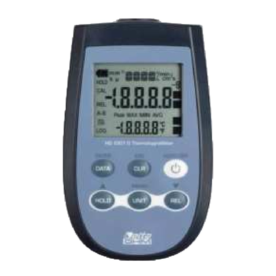
GEN ERAL CH ARACTERI STI CS The Therm ohygrom et er Model H D 2 3 0 1 .0 is a port able inst rum ent t hat m easures an environm ent 's t em perat ure and relat ive hum idit y. I t is fit t ed w it h a lar ge LCD display for excellent visualizat ion of t he m easured dat a. - Page 4 Th e r m oh ygr om e t e r H D 2 3 0 1 .0 - 4 - HD2301 V1.7...
- Page 5 H D 2 3 0 1 .0 1. I nput for probes, 8- pole DI N45326 connect or. 2. Bat t ery sym bol: displays t he bat t ery charge level. 3. Funct ion indicat ors. 4. Secondary t em perat ure display line. 5.
-
Page 6: D Escri Pti On Of Th E Fun Cti On S
D ESCRI PTI ON OF TH E FUN CTI ON S The keyboard of t he t herm ohygrom et er H D 2 3 0 1 .0 is com posed of double- funct ion keys. The funct ion on t he key is t he " m ain funct ion" , while t he one above t he key is t he "... - Page 7 D isa bling of t he a ut om a t ic t ur ning off The inst rum ent has an Aut oPowerOff funct ion t hat aut om at ically t urns t he inst rum ent off aft er about 8 m inut es if no key is pressed dur ing t he int ervening t im e. Press sim ult aneously t he ON / OFF key and t he H OLD key t o disable t his funct ion.
- Page 8 • : once t he MENU has been opened wit h t he D ATA+ UN I T keys, t he key will allow t o increase t he value of t he select ed param et er. Pressed t oget her wit h t he ON / OFF key, during t urn on, t he Aut oPowerOff funct ion is disabled ( see t he descript ion of t he ON/ OFF key) .
-
Page 9: Th E Program M I N G M En U
TH E PROGRAM M I N G M EN U To access t o t he m enu press sim ult aneously t he follow ing keys: The it em s t o be set are list ed in t his order: 1 . -
Page 10: Probes An D M Easurem En
PROBES AN D M EASUREM EN TS The inst rum ent H D 2 3 0 1 .0 works by using com bined hum idit y/ t em perat ure probes ( t em perat ure wit h a Pt 100 sensor) and wit h t em perat ure only probes wit h 4 w ir e Pt 100, or 2 or 4 w ire Pt 1000. -
Page 11: Cali Brati On Of The Combi Ned Humi Di Ty / Temperature Probe
ALI BRATI ON OF TH E COM BI N ED H UM I D I TY TEM PERATURE PROBE Ca u t ion ! To calibrat e t he probes correct ly, a know ledge of and abiding by t he physical phenom ena on which t he m easurem ent is based is fundam ent al: t his is t he reason why it is recom m ended t o abide by what is report ed below carefully and only t o perform new calibr at ions if t echnically pr oficient . - Page 12 Ca libr a t in g t h e point s a t 3 3 % RH a n d 1 1 % RH Repeat t he point s from 3) t o 9) using t he sat urat ed salt s at 33% RH and 11% When com plet ed, unscrew t he ring wit h t he cap, and screw t he prot ect ion grid back on t he sensors.
-
Page 13: D I Rect I Nput I Nto Pt 100 And Pt 1000 Temperature Probes
Pt 1 0 0 Pt 1 0 0 0 T I RECT I N PUT I N TO AN D EM PERATURE PROBES The inst rum ent accept s t he input of Plat inum t em perat ure probes wit h resist ances of 100Ω... - Page 14 5. open t he t wo m odule shells: t he pr int ed circuit t o which t he probe m ust be connect ed is housed inside. On t he left t here are t he 1…4 point s on which t he sensor wires m ust be welded.
-
Page 15: I Rect Connecti On Of Wi Re Pt 100 Sensors
8. I nsert t he gasket in t he m odule; 9. Screw t he fair lead and t he r ing. 10.At t he ot her end of t he m odule, ent er t he r ing w it h t he O- Ring as indicat ed in t he pict ure. -
Page 16: W Arn I N
W ARN I N GS 1. Probes are not insulat ed from t heir ext ernal casing; be very careful not t o com e int o cont act w it h live part s ( above 48V) . This could be ext rem ely dangerous for t he inst rum ent as well as for t he operat or, who could be elect rocut ed. -
Page 17: I N Strum En T Si Gn Als An D Faults
I N STRUM EN T SI GN ALS AN D FAULTS The follow ing t able list s all error indicat ions and inform at ion displayed by t he inst rum ent and supplied t o t he user in different operat ing sit uat ions: I ndica z ione a displa y Spie ga z ione This appears in t he display cent ral line when a t em perat ur e only... -
Page 18: Low Battery W Arn I N G An D Battery Replacem En
LOW BATTERY W ARN I N G AN D BATTERY REPLACEM EN T The bat t ery sym bol on t he display const ant ly shows t he bat t er y charge st at us. To t he ext ent t hat bat t er ies have discharged, t he sym bol "... -
Page 19: I N Strum En T Storage
I N STRUM EN T STORAGE I nst rum ent st orage condit ions: • Tem perat ure: - 25...+ 65 ° C. • Hum idit y: less t han 90% RH wit hout condensat ion. • Do not st ore t he inst rum ent in places where: •... -
Page 20: Notes Aboutw Orki N Gan D Operati Ve Safety
N OTES ABOUT W ORKI N G AN D OPERATI VE SAFETY Au t hor ize d use The t echnical specificat ions as given in chapt er TECHNI CAL CHARACTERI STI CS m ust be observed. Only t he operat ion and running of t he m easur ing inst rum ent according t o t he inst ruct ions given in t his operat ing m anual is aut hor ized. -
Page 21: Tech N I Cal Ch Aracteri Sti
TECH N I CAL CH ARACTERI STI CS ECH N I CAL I N FORM ATI ON ON TH E H ERM OH YGROM ETER I nst rum ent Dim ensions ( Lengt h x Widt h x Height ) 140 x 88 x 38 m m Weight 160 g ( com plet e w it h bat t eries) -
Page 22: Techni Cal Data Of Probes And Modules I N Li Ne Wi Th The I Nstrument
ECH N I CAL D ATA OF PROBES AN D M OD ULES I N LI N E W I TH TH E I N STRUM EN T Pt 1 0 0 SI CRAM EM PERATURE PROBES SEN SOR USI N G M OD ULE Applica t ion M ode l... -
Page 23: Relati Ve Humi Di Ty And Temperature Probes Usi Ng Si Cram Module
ELATI VE H UM I D I TY AN D TEM PERATURE PROBES U SI N G SI CRAM M OD ULE Applica t ion r a n ge Accu r a cy Te m p M ode l se nsor % RH Te m pe r a t u r e % RH... -
Page 24: Ord Eri N G Cod
ORD ERI N G COD ES The kit is com posed of t he inst rum ent HD2301.0, 3 1.5V alkaline H D 2 3 0 1 .0 bat t eries, operat ing m anual, and case. The pr obe s m u st be or de r e d se pa r a t e ly. - Page 25 PBT and 10 µm st ainless st eel gr id prot ect ion for probes Ø14, t hread M12x1. Operat ing t em perat ure: - 40…120 ° C. H D 7 5 Sat urat ed solut ion for checking t he Relat ive Hum idit y sensor at 75% RH, wit h screw adapt or for Ø14 probes, t hread M12×...
- Page 26 SI CRAM EM PERATURE PROBES W I TH OUT M OD ULE TP4 7 .1 0 0 .O I m m ersion probe, sensor Pt 100 direct 4 wires. Probe's st em Ø3 m m , lengt h 230 m m . 4- w ire connect ion cable w it h connect or, lengt h 2 m et res.
- Page 28 GHM GROUP – Delt a OH M | Delt a Ohm S.r.l. a socio unico Via Marconi 5 | 35030 Caselle di Selvazzano | Padova | I TALY Phone + 39 049 8977150 | Fax + 39 049 635596 www.deltaohm .com | sales@deltaohm .com W ARRAN TY Delta OHM is required to respond t o the "fact ory warrant y"...
Need help?
Do you have a question about the DeltaOHM HD2301.0 and is the answer not in the manual?
Questions and answers