Table of Contents
Advertisement
Quick Links
Advertisement
Table of Contents

Related Manuals for Netafim NMC PRO CLIMATE


Summary of Contents for Netafim NMC PRO CLIMATE
-
Page 2: Table Of Contents
USER GUIDE NMC-PRO Table of Contents INTRODUCTION LIMATE ZONES NTERFACE Keyboard Main Menu Screen Overview Screen Quick Access Hot Keys IGHT TATUS EVEL CCESS SETUP System Setup (MENU 7.11) Temperature & Humidity Calibration (Menu 7.10.5) Weather Station Calibration (Menu 7.10.6) Up/Down Load Data Plug (Menu 7.12) Customize Overview (Menu 7.13) View Firmware Versions (Menu 7.14) - Page 3 USER GUIDE NMC-PRO HEATING – H 1.3) ROGRAM EATING – H 2.3) ANUAL EATING – H 4.3) TATUS EATING & H – A 5.2.3) ISTORY PPLICATION ISTORY EATING – H 7.3) ETUP EATING Heating ON/OFF (Menu 7.3.1) Heating Network (Menu 7.3.2) MISTING –...
- Page 4 USER GUIDE NMC-PRO CROP PROTECTION – C 1.8) ROGRAM ROTECTION – C 2.8) ANUAL ROTECTION – C 4.8) TATUS ROTECTION & H – A – C 5.2.8) ISTORY PPLICATION ISTORY ROTECTION – C 7.8) ETUP ROTECTION LIGHT – L 1.9) ROGRAM IGHT –...
-
Page 5: Introduction
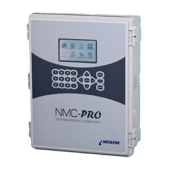
NMC-PRO INTRODUCTION NMC Pro Climate is a climate controller that enables the user to control climate conditions, setting them to the required level inside the climate zone (see zone explanation). NMC Pro Climate controls up to four climate zones in a single controller. -
Page 6: User Interface
USER GUIDE NMC-PRO NTERFACE Keyboard Numeric - Enter values/quantities - Use as shortcuts to screens +/- Key - Toggle between positive and negative values - Mark check boxes - Use to toggle between quantities and time format in History screens Arrows - Scroll up, down, left, and right to select menus MENU... -
Page 7: Overview Screen
USER GUIDE NMC-PRO Overview Screen Wind Wind Date & Time Menu # & Title Speed Direction 4.0 Overview 19/01/09 16:21 Radiation Humidity Weather Station Temp Rad S. Radiation Temperature 12.0 40.5 1400 ZONE 4 ZONE 1 ZONE 2 ZONE 3 1. -
Page 8: Quick Access
USER GUIDE NMC-PRO Quick Access Use the Quick Access feature in order to navigate into any screen by entering in the corresponding numeric keys of the menu (top left of screen) from the Main Menu screen. There is a permanent order in the layout of the screens. For double digit numbers, use the key for the ten’s place and then the corresponding one’s place number... -
Page 9: Ccess
USER GUIDE NMC-PRO EVEL CCESS There are three levels of access: • Read Only (restricted) All the parameters and menus are visible, but cannot be modified • User (limited restriction) Menus 1-7 are fully accessible and can be modified. Menu 8 can be viewed but not edited •... -
Page 10: Setup
USER GUIDE NMC-PRO SETUP System Setup (MENU 7.11) 7.11 System setup 19/01/09 16:21 1. Time 16:21:33 2. Date 19/Jan/09 3. Units Metric 4. Language English Communication 5. Controller number 6. Lower Port baud rate 9600 7. Upper Port baud rate 19200 8. - Page 11 USER GUIDE NMC-PRO Parameter Explanation Unit/Range Default Weather Station Define controller operation as one of the following: • LOCAL: Works only in the current location and is not dependent nor serves as a main controller Local Weather • SLAVE: Receives weather station Slave Local Station...
- Page 12 USER GUIDE NMC-PRO Parameter Explanation Unit/Range Default Define the duration of time to measure 18. Rain off delay 01:00 stopped rain for the controller to no longer recognize it as a Rain event Define the minimum temperature (°C) to 19. Snow Limit °C indicate a snow event in addition or instead of a Snow detector Define the duration of time to measure...
-
Page 13: Temperature & Humidity Calibration (Menu 7.10.5)
USER GUIDE NMC-PRO Temperature & Humidity Calibration (Menu 7.10.5) 7.10.5 Temp. & Hum Zone 1 19/01/09 16:21 Inp Unit Function Value Local Temp. Out 24.0 Local Temp. In 24.1 Local Humidity Local Temp. In 24.0 Local Humidity 72.1 Local Temp. In Remote Humidity 80.0... -
Page 14: Weather Station Calibration (Menu 7.10.6)
4. Radiation damping – percentage taken from older reading (remaining percentage taken from the newer reading) Wind Speed 5. Wind speed sensor type – Select the sensor brand (Netafim/Davis) 6. Wind speed damping – percentage taken from older reading (remaining percentage taken from the newer reading) Wind direction 7. - Page 15 USER GUIDE NMC-PRO Rain Sensor 11. Quantity per pulse mm – the quantity of rain per tipping. A Rain Collection sensor must be installed for this parameter to be valid. 12. Rain detector sensitivity – set the voltage for rain detection (0-15) NOTE: Parameter refers to an installed Rain Detector used for automatic detection of a start and end of a rain event (Normally Open, closed during rain) 13.
-
Page 16: Up/Down Load Data Plug (Menu 7.12)
USER GUIDE NMC-PRO Up/Down Load Data Plug (Menu 7.12) Read Data from Plug ACTION WILL OVERWRITE YOUR CONTROLLER DATA Use the arrow keys to select Yes ARE YOU SURE? Press Enter DATA ON PLUG Set Name: NMC Climate PRO Use the arrow keys to select Yes Save Date: 23-03-09 Save Time: 06:28:06 Press Enter, and wait for next screen... -
Page 17: Customize Overview (Menu 7.13)
√ 13. V. End lee % √ View Firmware Versions (Menu 7.14) 7.14 FM Versions 19/01/09 16:21 Netafim – NMC Pro Climate 1. Software version 8.2.85 2. Release date 05/Oct/09 3. Expansion box SW version 2.01 4. RTU SW version 1.12... -
Page 18: Vent
USER GUIDE NMC-PRO VENT – V 1.1) ROGRAM The goal of the Ventilation process is to maintain a fixed temperature in the green house. The Ventilation control manages the vents operation according to the conditions of the greenhouse. The monitoring and operation is done per control (1-3) and within the control number the controller should operate the vent individually. - Page 19 USER GUIDE NMC-PRO IMPORTANT: Verify that the SETUP parameters have been defined and the vents Calibrated! 1.1 Vent Prg. Zone 1 19/01/09 16:21 1. Period 2. Active 3. Start hh:mm 06:00 18:00 4. Top temp °C 24.0 5. Side temp °C 26.0 6.
- Page 20 USER GUIDE NMC-PRO Parameter Explanation Unit/Range Default Define the conversion table that indicates the influence of the wind speed level outside on the Wind Influence 0-50 m/sec ventilation temperature. Influence *See Wind Speed below Define the gradual cooling down time per 1 (approximately 2F).
-
Page 21: Solar Radiation Influence
USER GUIDE NMC-PRO Solar Radiation Influence Solar radiation increases the greenhouse temperature. During higher levels of radiation set the table to negative values to decrease the temperature to a lower set point. This does not mean that the set point changes, simply that the radiation level influences the temperature of the Calculated vent temperature. -
Page 22: Humidity Influence
USER GUIDE NMC-PRO Humidity Influence Depending on the crop humidity requirements, a negative value for the temperature decreases the humidity (humidity release treatment) while a positive value increases the humidity (humidification treatment). The following example is for decreasing humidity by opening the vents earlier. Humidity Influence the Vent Temperature Humidity Desired Vent temp. -
Page 23: Wind Speed Influence
USER GUIDE NMC-PRO Wind Speed Influence Take into consideration the overall climate throughout the season in order for the wind speed influence to accurately control the greenhouse climate. If the season is summer, for example, than the vents need to be opened more frequently for ventilation. -
Page 24: Manual - Vent (Menu 2.1)
USER GUIDE NMC-PRO – V 2.1) ANUAL 2.1 Vent Manual Zone 2 19/01/09 16:21 1. Vent # 2. Vent Type LSide ESide Top1 3. Drive Vent Auto Open Fixed 4. Fixed Position % 5. Meas. Position % 30.5 6. Calc. Position % 30.5 7. -
Page 25: Status - Vent (Menu 4.1)
USER GUIDE NMC-PRO – V 4.1) TATUS 4.1 Vent Status Zone 2 19/01/09 16:21 1. Top vent temp target °C 24.5 2. Side vent temp target °C 3. Radiation influence °C -1.0 4. Humidity influence °C -0.5 5. Wind speed influence °C 6. -
Page 26: Log & History
USER GUIDE NMC-PRO & H – A – V 5.2.1) ISTORY PPLICATION ISTORY 5.2.1 Vent His. Zone 2 19/01/09 16:21 History includes the last 3 days 1. Vent number 2. Vent type LSide ESide Top1 3. Total move Lee 4. Total move Wind 5. -
Page 27: Setup - Vent (Menu 7.1)
USER GUIDE NMC-PRO – V 7.1) ETUP 7.1 Vent setup Zone 1 19/01/09 16:21 Top1 1. Vent control 2. Period 3. Active 4. Start hh:mm 06:00 18:00 5. Temp diff wind °C 6. Temp diff lee °C 7. Max vent wind % 8. - Page 28 USER GUIDE NMC-PRO Parameter Explanation Unit/Range Default Define the minimum percentage for opening/closing the vent from the Minimum Step current position to the calculated. If 0 - 100% size calculated position percentage is below this percentage, then the vent will not increase/decrease its position.
-
Page 29: Setup - System Calibration
USER GUIDE NMC-PRO Parameter Explanation Unit/Range Default Maximum Vent lee (Max. % (0 – 100) Wind) Maximum vent opening on the lee/wind side when wind speed is above the Maximum Maximum Wind for Vent Influence. Vent wind % (0 – 100) (Max. - Page 30 USER GUIDE NMC-PRO Manual Calibration To ensure that vents perform accurately, manually calibrate the system at regular intervals. There are two calibration methods which differ in how the vent movement is measured: • TIME: Calibrate the vent according to the Running Time (time that elapses from fully open to fully closed).
- Page 31 USER GUIDE NMC-PRO Automatic Calibration Automatic calibration is done at a time specified by the user, once a day. If required, you can reconfigure the NMC-Pro to recalibrate the same day. Each motor can have a different calibration time. Note: Calibration is performed according to a system of priorities. If the motor is engaged in a higher priority action (for example manual operations), calibration does not take place.
-
Page 32: Screen
USER GUIDE NMC-PRO SCREEN – S 1.2) ROGRAM CREEN The goal of the Screens process is to maintain certain energy in the green house. The Screen control manages the screens operation according to the conditions of the greenhouse. The monitoring and operation is done per zone; the system operates each screen individually, and each day is divided into several periods. - Page 33 USER GUIDE NMC-PRO IMPORTANT: Verify that the SETUP parameters have been defined and the screens Calibrated! 1.2 Screen Prg. Zone 1 19/01/09 16:21 1. Screen # 2. Active 3. Functionality Shade Shade 4. Start hh:mm 06:00 15:00 5. End hh:mm 14:00 18:00 6.
- Page 34 USER GUIDE NMC-PRO Parameter Explanation Unit/Range Default the settings defined for the higher priority, which is Energy. Note: Cannot set this parameter if the Screen Functionality is set to Shading Temperature The dead band of the temperature set to +50 dead band points Radiation limit...
-
Page 35: Manual - Screen (Menu 2.2)
USER GUIDE NMC-PRO – S 2.2) ANUAL CREEN 2.2 Screen manual Zone 2 19/01/09 16:21 1. Screen # 2. Screen Type Shade Energy 3. Drive Screen Auto Spread 4. Fixed Position % 5. Measured Position % 6. Calculated Position % 1. -
Page 36: Status - Screen (Menu 4.2)
USER GUIDE NMC-PRO – S 4.2) TATUS CREEN 4.2 Screen Status Zone 1 19/01/09 16:21 1. Screen # 2. Active as Shade Shade 3. Max Position % 4. Min Position % 5. Calc. temp gap % 6. Calc. humidity gap % 7. -
Page 37: Log & History - Application History - Screen (Menu 5.2.2)
USER GUIDE NMC-PRO & H – A – S 5.2.2) ISTORY PPLICATION ISTORY CREEN 5.2.2 Screen His. Zone 1 19/01/09 16:21 History includes the last 2 days 1. Screen # 2. Type Shade Energy 3. Total screen movement 4. Motors totl hrs hh:mm History includes the last X day/s –... -
Page 38: Setup - Screen (Menu 7.2)
USER GUIDE NMC-PRO – S 7.2) ETUP CREEN 7.2 Screen setup Zone 1 19/01/09 16:21 1. Screen # 2. Released 3. Min Position % 4. Max Position % 5. Energy Step Size % 6. Energy Step delay mm:ss 00:30 00:30 7. - Page 39 USER GUIDE NMC-PRO Parameter Explanation Unit/Range Default Screen If working with an external contact, Position when define the screen position percentage 0 - 100% external when an event occurs contact occurs Use Fan & Pad Select whether the screen spreading Yes/No influence will be influenced by a Fan &...
- Page 40 USER GUIDE NMC-PRO Temp Example: Temp Gap Curve Temperature Screen Pos (%) Humidity Example: Humidity Gap Curve Humidity (RH) Screen Pos (%) Doc. Name: NMC-PRO ׀User Guide Ver 3.05.03 Revision: 2.2 Page: 40 Crop Management Technologies...
-
Page 41: Screen
USER GUIDE NMC-PRO – S – S 7.10.2) ETUP YSTEM ALIBRATION CREEN 7.10.2 Screens Zone 1 19/01/09 16:21 1. Screen # 2. Drive screen % None 3. Calib pos % 4. Calibrate now 5. Auto Calib 6. Auto Calib hh:mm 00:00 00:00 Measurements... - Page 42 USER GUIDE NMC-PRO 9. Wait until the Calibrate now changes back 9. Wait until the Calibrate now changes to NO back to NO Calibration is complete! Calibration is complete! Go to 9. Curve mV-% to view readings Automatic Calibration Automatic calibration is done at a time specified by the user, once a day. If required, you can reconfigure the NMC-Pro to recalibrate the same day.
- Page 43 USER GUIDE NMC-PRO Measurements 7. Calculated position – Targeted position of the screen 8. Measured position – Current position of the screen 9. Control type – Method of which the screen movement is measured (time/measured) 10. Measured mV – Current mV read by the potentiometer corresponding with the screen position 11.
-
Page 44: Heating
USER GUIDE NMC-PRO HEATING – H 1.3) ROGRAM EATING The Heating system controls the desired temperature inside the greenhouse. The desired temperature is achieved by operating two different heating systems: 1. ON/OFF Heating 2. Water Heating Networks Defining one boiling system per controller will provide hot water for all the 4 zones. ON/OFF Heating in Greenhouse Heating network Ring line... - Page 45 USER GUIDE NMC-PRO IMPORTANT: Verify that the SETUP parameters have been defined for heating! 1.3 Heating Prg. Zone 1 19/01/09 10:21 1. Period 2. Active 3. Start hh:mm 06:00 15:00 4. Heating temp °C 17.0 5. Rad influence 6. Cool time hh:mm 00:15 00:15 7.
- Page 46 USER GUIDE NMC-PRO Parameter Explanation Unit/Range Default NO: The use of the heater is only for CO2 Release for Yes/No YES: The use of the heater is for both Temperature Heating and CO2 Dead band in reference to the heating -50°...
- Page 47 USER GUIDE NMC-PRO Doc. Name: NMC-PRO ׀User Guide Ver 3.05.03 Revision: 2.2 Page: 47 Crop Management Technologies...
-
Page 48: Manual - Heating (Menu 2.3)
USER GUIDE NMC-PRO – H 2.3) ANUAL EATING 2.3 Heating manual Zone 1 19/01/09 16:21 Network Heating 1. Network number 2. Drive mixing valve Auto Open 3. Low Speed Pump Auto Auto 4. High Speed Pump 5. Fixed water temp °C 6. -
Page 49: Status - Heating (Menu 4.3)
USER GUIDE NMC-PRO – H 4.3) TATUS EATING 4.3 Heating Stat Zone 1 19/01/09 16:21 1. Heating temp Target °C 17.0 2. Radiation influence °C 3. Cool down influence °C -1.0 4. Heat up influence °C 5. Calc. heating temp °C 18.5 6. - Page 50 USER GUIDE NMC-PRO Heating network 12. Actual heat capacity – Displays the heat kW transferred to the zone from each network 13. Calculated Min water temp – Displays the minimum temperature for the water with the humidity influence considered 14. Max water temp – Displays the maximum temperature for the water as defined in 7.3.1 Heating ON/OFF Setup 15.
-
Page 51: Log & History - Application History - Heating (Menu 5.2.3)
USER GUIDE NMC-PRO & H – A 5.2.3) ISTORY PPLICATION ISTORY EATING 5.2.3 Heating His Zone 1 19/01/09 16:21 History includes the last 5 days 1. Network # ON/OFF 2. Pump total hrs hh:mm 47:00 3. HS Pump total hh:mm 20:00 4. -
Page 52: Setup - Heating (Menu 7.3)
USER GUIDE NMC-PRO – H 7.3) ETUP EATING 1. Heating ON/OFF (Menu 7.3.1) 7.3.1 Heating On/ Zone 1 19/01/09 16:21 Heating Type ON/OFF 1. Max temp limit °C 2. Max CO2 concentration ppm 1500 3. Heating On delay mm:ss 05:00 4. -
Page 53: Heating Network (Menu 7.3.2)
USER GUIDE NMC-PRO 2. Heating Network (Menu 7.3.2) 7.3.2 Heating net Zone 1 19/01/09 16:21 1. Heating Control Network 1 2. Period 3. Active 4. Start time hh:mm 06:00 15:00 5. Max water temp °C 100.0 90.0 6. Min water temp °C 7. - Page 54 USER GUIDE NMC-PRO Parameter Explanation Unit/Range Default A four point table which defines the influence of the measured humidity in Influence of the greenhouse on the minimum pipe 0-100% Vs. Relative temperature. Humidity on the -100° to For example: If the humidity is high, then Minimum Water +100°...
- Page 55 USER GUIDE NMC-PRO Parameter Explanation Unit/Range Default Define the offset per network for the calculated water temperature. For example, if Network 1 is defined as Lagging = 0 and Network 2 is defined as 16. Lagging °C Lagging = -15° C when the calculated water temperature is 70°...
-
Page 56: Misting
USER GUIDE NMC-PRO MISTING – M 7.4) ROGRAM ISTING The Misting process in the Greenhouse should provide the ability to increase the Humidity or VPD* (vapor pressure deficit) and cool down the greenhouse zone temperature. The Misting program controls the misting valves by pulse base and pause time, with automatic adjustment according to desired value. - Page 57 USER GUIDE NMC-PRO IMPORTANT: Verify that the SETUP parameters have been defined for Misting! 1.4 Misting Prg. Zone 1 19/01/09 7:21 1. Period 2. Active 3. Start hh:mm 06:00 08:00 4. Release 5. Start trig. Temp 6. Stop trig. Temp 7.
- Page 58 USER GUIDE NMC-PRO Parameter Explanation Unit/Range Default Temp limit If ‘Temp’ is selected as the Start/Stop trigger, °C then above this set point, the misting program will start and below the dead band, the Temp dead band °C misting will stop. If ‘Hum’...
-
Page 59: Enu
USER GUIDE NMC-PRO – M 2.4) ANUAL ISTING 2.4 Misting manual Zone 1 19/01/09 16:21 1. Drive Pump Auto 2. Valve # 3. Drive valve Auto 4. Status Spray Spray Pause Wait 1. Drive Pump (Press Enter to display drop-down menu) ... -
Page 60: Status - Misting (Menu 4.4)
USER GUIDE NMC-PRO – M 4.4) TATUS ISTING 4.4 Misting Stat Zone 1 19/01/09 16:21 1. Misting system status 2. Actual start trigger 3. Actual stop trigger None 4. Pump status Rest 5. Max valves allowed 6. Limitations None Misting Valve 7. -
Page 61: Log & History
USER GUIDE NMC-PRO & H – A – M 5.2.4) ISTORY PPLICATION ISTORY ISTING 5.2.4 Misting His Zone 1 19/01/09 16:21 History includes the last 5 days Misting Pump 1. Pump total hours hh:mm 30:00 2. Electrical capacity kw/h 3. Num. times switched on Misting Valves 4. -
Page 62: Enu 5.2.4)
USER GUIDE NMC-PRO – M 7.4) ETUP ISTING 7.4 Misting setup Zone 1 19/01/09 16:21 Mist valve # 1. Max pulse 0:01:00 0:01:00 0:00:00 2. Min pulse 0:00:05 0:00:05 0:00:00 3. Max pause 0:05:00 0:05:00 0:00:00 4. Min pause 0:00:10 0:00:10 0:00:00 Calculated... -
Page 63: Fan & Pad
USER GUIDE NMC-PRO FAN & PAD – F & P 1.5) ROGRAM The Fan & Pad process in the Greenhouse enables cooling the interior environment and maintaining a fixed humidity and temperature inside the greenhouse. The grower can define up to eight fan stages per each zone. The Fan &... - Page 64 USER GUIDE NMC-PRO IMPORTANT: Verify that the SETUP parameters have been defined and the Fan&Pad Inlet Calibrated! 1.5 Fan_Pad Prg. Zone 1 19/01/09 16:21 1. Period 2. Active 3. Start hh:mm 10:00 14:00 4. Temp limit °C 27.0 30.0 5. Release Pad Pump 6.
- Page 65 USER GUIDE NMC-PRO Parameter Explanation Unit/Range Default The system checks the difference between the inside humidity and outside. If the difference is higher Difference Between than the set point, the humidity Inside and Outside -100% to +100% release process begins. Humidity This parameter exists only when Trigger or Trigger+Timer mode are...
-
Page 66: Manual - Fan & Pad (Menu 2.5)
USER GUIDE NMC-PRO – F & P 2.5) ANUAL 2.5 Fan_Pad manual Zone 1 19/01/09 16:21 Fan Stage 1. Fan stage # 2. Drive fan stage Auto Auto Auto 3. Status Fan&Pad Inlet 4. Drive inlet Fixed 5. Fixed position % 6. -
Page 67: Status - Fan & Pad (Menu 4.5)
USER GUIDE NMC-PRO – F & P 4.5) TATUS 4.5 Fan_Pad Stat Zone 1 19/01/09 16:21 1. Fan&Pad active Temp 2. Fan&Pad start temp °C 26.0 3. Number of active fans 4. Pad Pump status 5. Air inlet calc. pos % 6. -
Page 68: Log & History
USER GUIDE NMC-PRO & H – A – F & P 5.2.5) ISTORY PPLICATION ISTORY 5.2.5 Fan_Pad His Zone 1 19/01/09 16:21 History includes the last days Fan Stage 1. Fan stage # 2. Total oper. hh:mm 00:00 00:00 00:00 3. -
Page 69: Setup - Fan & Pad (Menu 7.5)
USER GUIDE NMC-PRO – F & P 7.5) ETUP 7.5 Fan_Pad setup Zone 1 19/01/09 16:21 1. Stages on delay mm:ss 00:20 2. Stages off delay mm:ss 00:12 3. Pad Pump start temp °C 25.5 4. Pad Pump stop temp °C 23.0 5. - Page 70 USER GUIDE NMC-PRO Parameter Explanation Unit/Range Default If the humidity inside the greenhouse Humidity limit pad is higher than this value, then the pump off controller will turn off the pad pump. Fan Stage Setup 10. Fan stage when rain During special events such as: rain, storm, frost, external condition and 11.
-
Page 71: System Calibration - Fan & Pad
USER GUIDE NMC-PRO – S – F & P 7.10.3) ETUP YSTEM ALIBRATION NLET 7.10.3 F&P Inlet Zone 1 19/01/09 16:21 1. AirInlet # 2. Drive F&P inlet % None 3. Calib pos % 4. Calibrate now 5. Auto Calib 6. - Page 72 USER GUIDE NMC-PRO to NO back to NO Calibration is complete! Calibration is complete! Go to 9. Curve mV-% to view readings 1. Air Inlet # – Air Inlet number corresponding with the Digital Outputs – System Installation menu 2. Drive F&P inlet % (Press Enter to display drop-down menu) None - Operates as defined in the Fan&Pad Program ...
- Page 73 USER GUIDE NMC-PRO Measurements 7. Calculated position – Targeted position of the inlet 8. Measured position – Current position of the inlet 9. Control type – Method of which the inlet movement is measured (time/measured) 10. Measured mV – Current mV read by the potentiometer corresponding with the inlet position 11.
-
Page 74: Air Circulation
USER GUIDE NMC-PRO AIR CIRCULATION – A 1.6) ROGRAM IRCULATION Air Circulation in the greenhouse: 1. Prevents differences of temperature/humidity inside a zone 2. Removes humidity from the foliage of plants – bring a fresh supply of CO to the leaves 3. - Page 75 USER GUIDE NMC-PRO IMPORTANT: Verify that the SETUP parameters have been defined for air circulation! 1.6 Air circ. Prg. Zone 1 19/01/09 16:21 1. Period 2. Active 3. Start time hh:mm 06:00 4. End time hh:mm 10:00 5. Valid conditions no. 6.
- Page 76 USER GUIDE NMC-PRO Parameter Explanation Unit/Range Default Define the temperature set point and the direction above/below to start air circulation. NOTE: Press ENTER to edit, then use Temp Limit 0° to +50° C 25.0 +/- button to adjust arrow direction, press ENTER and use the number keypad to define the limit, press ENTER again to exit the parameter.
-
Page 77: Manual - Air Circulation (Menu 2.6)
USER GUIDE NMC-PRO Parameter Explanation Unit/Range Default use the number keypad to define the limit, press ENTER again to exit the parameter. Humidity difference dead band Humidity diff dead 0 - 100% for air circulation system band operation Calculation/Status 14. Air Circulation Status Status of the air circulation Air Circulation Displays any limitation to the air... -
Page 78: Status - Air Circulation (Menu 4.6)
USER GUIDE NMC-PRO – A 4.6) TATUS IRCULATION 4.6 Air Circ. Stat Zone 1 19/01/09 16:21 Measured Act. 1. Temperature °C 28.2 2. Humidity % 3. Temp difference °C 4. Humidity difference % 5. A. circ with heating Free 6. A. circ with spread sc Free 7. -
Page 79: Log & History
USER GUIDE NMC-PRO & H – A – A 5.2.6) ISTORY PPLICATION ISTORY IRCULATION 5.2.6 Air Circ. His Zone 1 19/01/09 16:21 History includes the last days 1. Min temp °C 24.8 2. Max temp °C 31.0 3. Min humidity % 4. -
Page 80: Setup - Air Circulation (Menu 7.6)
USER GUIDE NMC-PRO – A 7.6) ETUP IRCULATION 7.6 Air circ. set Zone 1 19/01/09 16:21 1. Use temperature limit 2. Use humidity limit 3. Use temperature difference 4. Use humidity difference 5. Air circ. when heating Free 6. Air circ. when screen spread Free 7. -
Page 81: Co2
USER GUIDE NMC-PRO – CO2 (M 1.7) ROGRAM The CO Process should maintain a certain level of CO inside the greenhouse. The CO program controls up to two CO valves per zone and one CO Fan transport per controller. The operation of the CO is dependent on the greenhouse temperature, the solar radiation and vent positions. - Page 82 USER GUIDE NMC-PRO IMPORTANT: Verify that the SETUP parameters have been defined and the CO Sensor/s calibrated! 1.7 CO2 Program Zone 1 19/01/09 16:21 1. Period 2. Active 3. CO2 mode Pass. Act. 4. Start hh:mm 05:30 14:00 5. End hh:mm 11:45 16:00 6.
- Page 83 USER GUIDE NMC-PRO Parameter Explanation Unit/Range Default The controller starts the CO process when Dead band ON it is below the desired concentration minus the Dead band ON. Four point table that describes the influence of the radiation level on the Radiation desired CO in the greenhouse (Increases...
- Page 84 USER GUIDE NMC-PRO Vent Influence the desired CO Concentration Vent Influence Example: Vent Pos Des CO2 (ppm) Define how much to decrease the CO concentration according to the vent position (the higher the vent position percentage, the higher the CO influence should be decreased).
-
Page 85: Status - Co2 (Menu 4.7)
USER GUIDE NMC-PRO – CO2 (M 4.7) TATUS 4.7 CO2 Status Zone 1 19/01/09 16:21 1. CO2 mode Pass. 2. CO2 status 3. Radiation influence ppm 4. Vent influence ppm -100 5. Calc. CO2 concent. ppm 6. Meas. CO2 concent. ppm 1000 7. -
Page 86: Log & History - Application History - Co2 (M Enu 5.2.7)
USER GUIDE NMC-PRO & H – A – CO2 (M 5.2.7) ISTORY PPLICATION ISTORY 5.2.7 CO2 His. Zone 1 19/01/09 16:21 History includes the last days 1. CO2 total hours hh:mm 5:05 2. Maximum level ppm 1200 3. Average level during opr ppm History includes the last X day/s –... - Page 87 USER GUIDE NMC-PRO – CO2 (M 7.7) ETUP 7.7 CO2 setup Zone 1 19/01/09 16:21 1. Max CO2 concentration ppm 1500 2. Max inside temp °C Parameter Explanation Unit/Range Default The maximum allowed CO concentration Maximum CO 0 - 2500 ppm 1000 per zone.
-
Page 88: Crop Protection
USER GUIDE NMC-PRO CROP PROTECTION – C 1.8) ROGRAM ROTECTION The Crop Protection process in the green house does not operate on a regular basis, the grower determines when it will activate. The Crop protection program provides four steps. The user can enable/disable one or more of the following steps: 1. - Page 89 USER GUIDE NMC-PRO IMPORTANT: Verify that the SETUP parameters have been defined for crop protection! 1.8 Crop Prot. pr Zone 1 19/01/09 16:21 1. Stat day/time 30/Nov 06:00 2. Phase Prep. Spray Proc. 3. Phase ON/OFF 4. Active 5. Phase time mm:ss 00:00 00:00 00:00...
- Page 90 USER GUIDE NMC-PRO Parameter Explanation Unit/Range Default Define activity of MISTING during Crop Protection: Misting Free – according to Misting program Free/No No – disables Misting during Crop Protection Define activity of AIR CIRCULATION during Crop Protection: Free – according to Air Circulation program Air Circulation Free/Yes/No...
-
Page 91: Manual - Crop Protection (Menu 2.8)
USER GUIDE NMC-PRO – C 2.8) ANUAL ROTECTION 2.8 Crop Prot. man Zone 1 19/01/09 16:21 1. Drive crop protection Auto 2. Status Auto 1. Drive crop protection (Press Enter to display drop-down menu) Auto - Operates as defined by the crop protection program ... -
Page 92: Status - Crop Protection (Menu 4.8)
USER GUIDE NMC-PRO – C 4.8) TATUS ROTECTION 4.8 Crop Prot St. Zone 1 19/01/09 16:21 1. Crop Protection Status Idle 2. Elapsed phase time hh: 00:00 3. Air circulation 4. Number of Fan stages 5. Screen Position % 6. Vent lee position % 7. -
Page 93: Log & History - Application History - Crop Protection (Menu 5.2.8)
USER GUIDE NMC-PRO & H – A – C 5.2.8) ISTORY PPLICATION ISTORY ROTECTION 5.2.8 Crop Prot. Zone 1 19/01/09 16:21 1. Crop Prot date&time 00/Jan/00 00:00 2. Cycle time hh:mm 00:00 3. Crop Prot date&time 00/Jan/00 00:00 4. Cycle time hh:mm 00:00 5. -
Page 94: Setup - Crop Protection (Menu 7.8)
USER GUIDE NMC-PRO – C 7.8) ETUP ROTECTION 7.8 Crop Prot. Set Zone 1 19/01/09 16:21 Start day/time 30/Nov 6:00 1. Phase Prep. Spray Proc. 2. Active 3. Use fan stage 4. F&P inlet pos % 5. Use fan stage 1 6. -
Page 95: Light
USER GUIDE NMC-PRO LIGHT – L 1.9) ROGRAM IGHT The Lighting devices in the greenhouse provide the ability to supply the crop with the specific quantity of light required. The Light control in the greenhouse manages the HID lamp operation and each zone may include up to four light strings. There are two types of lighting control methods: o Cyclic o Fixed... - Page 96 USER GUIDE NMC-PRO IMPORTANT: Verify that the SETUP parameters have been defined for Light! 1.9 Light Program Zone 1 19/01/09 16:21 1. Period 2. Active 3. Start time hh:mm 06:00 4. End time hh:mm 10:00 5. Light method Fixed 6. Rad. limit W/m 7.
-
Page 97: Manual - Light (Menu 2.9)
USER GUIDE NMC-PRO Parameter Explanation Unit/Range Default The lighting will turn on below this value Radiation Limit of radiation The lighting will turn off when radiation Radiation Dead reaches the Radiation Limit + Radiation band Dead band Light String 1 If operating according to the Cyclic Light String 2 method, the lights operate with each... -
Page 98: Status - Light (Menu 4.9)
USER GUIDE NMC-PRO – L 4.9) TATUS IGHT 4.9 Light Status Zone 1 19/01/09 16:21 1. String # 2. Light mode Fixed Fixed 3. String ON time hh:mm 00:00 00:00 4. String time elapsed 00:00 00:00 5. Rad sum inside J/m 6. -
Page 99: Log & History - Application History - Light (Menu 5.2.9)
USER GUIDE NMC-PRO & H – A 5.2.9) ISTORY PPLICATION ISTORY IGHT 5.2.9 Light His Zone 1 19/01/09 16:21 History includes the last days 1. Light string num 2. Total hours hh:mm 00:00 00:00 00:00 3. Elec. Capacity - kwh History includes the last X day/s –... -
Page 100: Setup - Light (Menu 7.9)
USER GUIDE NMC-PRO – L 7.9) ETUP IGHT 7.9 Light setup Zone 1 19/01/09 16:21 1. Switch On delay mm:ss 00:05 2. Switch Off delay mm:ss 00:03 3. Off level radiation sum W/m 15000 4. Time to reset radiation sum 07:00 5. -
Page 101: Alarm
USER GUIDE NMC-PRO ALARM 3.1) ESET LARM MENU 3.1 Reset Alarm Zone 1 19/01/09 16:21 1. Reset Now? 2. Period of automatic reset 1 hr Active Alarms Event Date Time Reset Now? (Press ENTER to display drop-down menu) No – Alarms are not reset Current Zone –... -
Page 102: Alarm Definitions
USER GUIDE NMC-PRO LARM EFINITIONS Process Alarms (Menu 3.3.1) 3.3.1 Proc. Alarm 19/01/09 16:21 Name Limit Delay Action Temp defect 01:00 Ignore Hum defect 01:00 Ignore CO2 defect 01:00 Ignore High temp 35.0 01:00 Low temp 15.0 01:00 High hum 95.0 01:00 Low hum... -
Page 103: Test
USER GUIDE NMC-PRO TEST ELAY In this menu, the relays that have been defined under the System Installation – Digital Outputs (Menu 8.1.1) can be tested manually. The "manual" action turns the relay on. After a period of five minutes the relay will turn off if left idle. NALOG NPUTS Displays analog inputs as defined in the System Installation –... -
Page 104: Log & History
USER GUIDE NMC-PRO LOG & HISTORY LIMATE History (Menu 5.1.1) NOTE: Must define the SETTINGS menu before being able to view the HISTORY! 5.1.1 Climate Hist Zone 1 19/01/09 16:21 Date & Time T. Avg T. Sn1 T. Sn2 18/01/09 23:00 17.0 17.0 17.0... -
Page 105: Application History
USER GUIDE NMC-PRO PPLICATION ISTORY APPLICATION REFER TO PAGE Vent Screen Heating Misting Fan&Pad Air Circulation Crop Protection Light 5.3) VENT Displays all changes made to the controller by the user 5.4) CTION Displays all controller device operations 5.5) YSTEM Displays all system events (software, firmware, cold starts, data plug) Doc. -
Page 106: Warranty
1 (one) year from the date of purchase by end user. If a defect is discovered during the applicable warranty period, Netafim will repair or replace, at its option, the product or the defective part. Note: Lightning and surge damages are not covered by the warranty. - Page 107 USER GUIDE NMC-PRO Doc. Name: NMC-PRO ׀User Guide Ver 3.05.03 Revision: 2.2 Page: 107 Crop Management Technologies...
Need help?
Do you have a question about the NMC PRO CLIMATE and is the answer not in the manual?
Questions and answers