Table of Contents
Advertisement
Quick Links
Advertisement
Table of Contents

Summary of Contents for clage Zip 27941
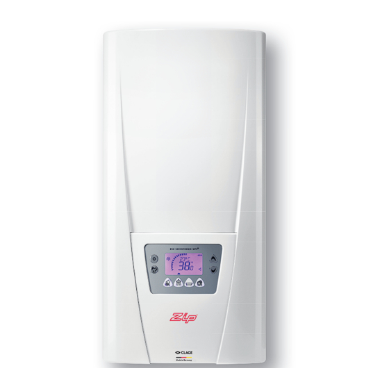
- Page 1 Instantaneous Hot Water Electronically controlled instantaneous water heater DSX: 27940 - 50 °C and 27941 - 60 °C models Installation instructions For 50 ºC models, the appliance delivers water not exceeding 50 ºC in accordance with AS3498...
-
Page 2: Table Of Contents
Contents 1. Safety instructions ....................3 2. -
Page 3: Safety Instructions
1. Safety instructions Please read these instructions carefully before installing or using the appliance! Keep the instructions handy with the appliance for future use! Installation, initial operation and maintenance of this appliance must only be con- ducted by an authorised professional, who will then be responsible for adherence to applicable standards and installation regulations. -
Page 4: Overview
2. Overview When ordering spare parts, please always specify the appliance model and serial number. Pos. Part.-No. Description Pos. Part.-No. Description Control panel support 99381 Hot water connection Outlet pipe Connecting terminal Safety thermal cut-out (STB) 99387 DSX control panel 99382 DSX / DEX thermal sensor set 2.1 Inlet pipe... -
Page 5: Technical Data
3. Technical data Model Part no. 27940 - 50 °C model 27941 - 60 °C model Energy efficiency class Rated capacity / rated current 18 kW..27 kW (26 A..39 A) 18 kW 21 kW 24 kW 27 kW 18 kW 21 kW 24 kW 27 kW... -
Page 6: Dimensions
4. Dimensions Dimensions in mm 5. Environment and recycling Your product was manufactured from high-quality, reusable materials and compo- nents. Please respect in case of discarding that electrical devices should be disposed of separately from household waste at the end of their service life. Therefore, please take this device to a municipal collection point that accepts electronic scrap. -
Page 7: Installation
6. Installation The following regulations must be observed: • Installation must comply with all statutory regulations, as well as those of the local electricity and water supply companies. • The rating plate and technical specifications • Only intact and appropriate tools must be used •... -
Page 8: Installing The Wall Bracket
6. Installation Installing the wall bracket Note: If you install this instantaneous water heater in exchange for a conventional instantaneous water heater, there is generally no need to drill holes for the wall brack- et, in this case step 2 would not be necessary. Thoroughly rinse the water supply pipes before installation to remove soiling from the pipes. -
Page 9: Installing The Appliance
6. Installation Installing the appliance 1. To open the appliance hood, take off the faceplate and unscrew the main hood screw. • When replacing an appliance, the electrical power supply cable may be connected in the upper part. Only in such case, follow the instructions “Electrical connection from above”. -
Page 10: Surface Mounted Installation
6. Installation Surface mounted installation Note: Fasten the screw nuts with caution, to avoid damage to the valves or the piping system. For direct connection, the two ½ inch screw-in nipples and the ½ inch seals must be screwed into the ½ inch union nuts of the hot-water and cold-water connectors. The two ½ inch caps of the side outlets of the hot-water and cold-water connectors must be removed and screwed onto the open end of the screw-in nipples. -
Page 11: Electrical Connection
7. Electrical connection Only by a specialist! Wiring diagram Please observe: • The installation must comply with current IEC and national local regulations or any particular regulations, specified by the local electricity supply company • The rating plate and technical specifications •... -
Page 12: Electrical Connection From Above
7. Electrical connection Electrical connection from above Check that the power supply is switched off prior to electrical connection! 1. Open the prepared breaking point (S) in the upper part of the appliance by pressing with a blunt implement (e.g. srewdriver). 2. -
Page 13: Initial Operation
8. Initial operation Before making the electrical connection, fill the mains and the appliance with water by carefully opening and closing the hot water tap in order to vent com- pletely. To ensure a maximum flow, remove any existing aerator from the faucet. Flush the warm and cold water pipes each at least for one minute. -
Page 14: Lock Level
8. Initial operation Lock level The operating mode of the appliance can be restricted. Activation of the lock level 1. Select required level of Lock level via the setup menu (see chapter “How to use, Setup menu”) 2. Disconnect the appliance from the power supply (e.g. by switching off the fuses) 3. -
Page 15: Maintenance Work
9. Maintenance work Maintenance work must only be conducted by an authorised professional. Cleaning and replacing the filter strainer The cold water connection of this instantaneous water heater is equipped with an inte- grated shut-off valve and a strainer. Soiling of the strainer may reduce the warm water output. - Page 16 Head Office As Zip’s policy is one of continuous product improvement, changes to Zip Water (Aust) Pty. Ltd specifications may be made without ABN: 46 000 578 727 prior notice. Images in this booklet 67-77 Allingham Street have been modified and may not be Condell Park NSW 2200 true representations of the finished Postal: Locked Bag 80...


Need help?
Do you have a question about the Zip 27941 and is the answer not in the manual?
Questions and answers