Advertisement
Available languages
Available languages
Quick Links
Helios Ventilatoren
MONTAGE- UND BETRIEBSVORSCHRIFT
INSTALLATION AND OPERATING INSTRUCTIONS
NOTICE DE MONTAGE ET D'UTILISATION
Kleinlüfter - Mini fan - Mini ventilateur
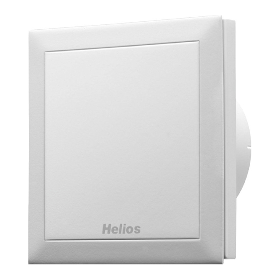
Helios MiniVent
M1/100 N / C
M1/120 N / C
- mit codierbarem Nachlauf- und Intervallbetrieb
- with codabel overrun timer and interval operation
- avec minuterie programmable et temporisation
NR. 19052.004
NO. 19052.004
N° 19052.004
IP 45
D
UK
F
Advertisement
Chapters

Related Manuals for Helios M1/100 N / C


Summary of Contents for Helios M1/100 N / C
- Page 1 N° 19052.004 IP 45 Kleinlüfter - Mini fan - Mini ventilateur Helios MiniVent M1/100 N / C M1/120 N / C - mit codierbarem Nachlauf- und Intervallbetrieb - with codabel overrun timer and interval operation - avec minuterie programmable et temporisation...
-
Page 2: Table Of Contents
DEUTSCH Helios Ventilatoren MONTAGE- UND BETRIEBSVORSCHRIFT NR. 19052.004 Inhaltsverzeichnis KAPITEL 1. ALLGEMEINE MONTAGE- UND BETRIEBSHINWEISE ........Seite 1 Wichtige Informationen . -
Page 3: Wichtige Informationen
Wenn die nachfolgenden Ausführungen nicht beachtet werden, entfällt unsere Gewährleistung. Gleiches gilt für Haf- tungsansprüche an den Hersteller. Der Gebrauch von Zubehörteilen, die nicht von Helios empfohlen oder angeboten werden, ist nicht statthaft. Eventuell auftretende Schäden unterliegen nicht der Gewährleistung. Wenn sich Feuchtigkeit im Klemmenkasten befindet ist die Tülle nicht fachgerecht ausgeführt. -
Page 4: Leistungsdaten
Die Geräte besitzen die Schutzart IP 45 (strahlwassergeschützt). Außerdem entsprechen sie der Schutzklasse II. 1.11 Typenübersicht MiniVent M1/1.. N / C M1/100 N / C mit codierbarem Nachlauf- und Intervallbetrieb Best.Nr. 6172.003 M1/120 N / C mit codierbarem Nachlauf- und Intervallbetrieb Best.Nr. -
Page 5: Lieferumfang / Verpackungseinheit
Die optimale Position liegt bei jeweils 45°, wenn sich der Kabelaustritt direkt an der Position der Kabeltülle befindet. - Rohrinnendurchmesser M1/100 N / C = 100 mm bzw. M1/120 N / C = 120 mm und Abstand zu Raum-Ecken: mindestens 90 mm... -
Page 6: Bohrlöcher
Montage- und Betriebsvorschrift MiniVent M1/100/120 N / C Bohrlöcher: Gehäuse ansetzen Löcher markieren und abbohren. Mit mind. zwei Befestigungsschrauben und Dübeln montieren. Bei Aufputzleitungsverlegung, muss die seitliche Aussparung für den Kabeleintritt (Abb.5, Pos Œ ) im Gehäu- se ausgebrochen werden! Das Anschlusskabel ist so zu verwahren, dass bei Wasserbeaufschlagung kein Wasser entlang des Kabels ACHTUNG eindringen kann. -
Page 7: Anschluss Der Zuleitung
Montage- und Betriebsvorschrift MiniVent M1/100/120 N / C Anschluss der Zuleitung 1. Es ist eine Mantel-Leitung bzw. im Feuchtraum eine NYM Leitung einzusetzen. 2. Leitungsaustritt aus der Wand mindestens 180 mm (Abb. 3). 3. Tülle mit rundem Werkzeug vorstechen oder mit der Zuleitung direkt durchstechen (Abb.5, Pos 3). 4. -
Page 8: Montageflansch Mf 100 (Zubehör)
Die einschlägigen Normen, Sicherheitsbestimmungen (z. B. DIN VDE 0100) sowie die TAB der EVUs sind unbedingt zu beachten. Elektronische Steuerplatine - M1/100 N / C serienmäßig mit codierbarem Nachlauf- und Intervallbetrieb - M1/120 N / C serienmäßig mit codierbarem Nachlauf- und Intervallbetrieb EMV-Vorschrift/Norm WICHTIGER HINWEIS Wichtiger Hinweis zur elektromagnetischen Verträglichkeit... -
Page 9: Reinigung Und Wartung
Montage- und Betriebsvorschrift MiniVent M1/100/120 N / C Reinigung KAPITEL 5 - Vor der Reinigung sicherstellen, dass das Gerät allpolig vom Netz getrennt ist! - Gegen Wiedereinschalten sichern! REINIGUNG UND - Gerät nur mit feuchtem Tuch reinigen. WARTUNG - Das Gerät ist wartungsfrei. Demontage der Fassade Vorgehensweise: 1. -
Page 10: Funktion Für M1/100/120 N / C
Folgende Funktionen sind implementiert: Jumper 1 (siehe SS-931) 1. Einschaltverzögerung (0 Sek, 45 Sek, 90 Sek, 120 Sek) – Typen M1/100 N / C DIP-Schalter S1-2 (siehe SS-920.1) Stellung A - Auslieferzustand Nach dem Einschalten der Klemme 1, beginnt der Ventilator erst nach der Kl. -
Page 11: Schaltplan-Übersicht Für M1/100/120 N / C
Montage- und Betriebsvorschrift MiniVent M1/100/120 N / C SCHALTPLAN-ÜBERSICHT Anschluss Kunde Internes Funktionsprinzip / Jumperstellung SS-931 M1/100 N / C M1/... N SS-917 M1/120 N / C M1/... NC Zeit-Eingang Manueller-Eingang a) Zeitfunktion b) manuell Ein Rückspannung / Raumbeleuchtung / Glimmlampen Jumper 1 Durch die Elektronik liegt an der Klemme 1 eine „... - Page 12 ENGLISH Helios Ventilatoren INSTALLATION AND OPERATING INSTRUCTIONS NO. 19052.004 Contents CHAPTER 1. GENERAL INFORMATION ............Page 1 Important information .
-
Page 13: Important Information
If the preceding instructions are not observed all warranty claims and accommodation treatment are excluded. This also applies to any liability claims extended to the manufacturer. The use of accessories not offered or recommended by Helios is not permitted. Potential damages are not liable for warranty. -
Page 14: General Information
In addition, they correspond to the safety class II. 1.11 Overview of types MiniVent M1/1.. N / C M1/100 N / C with codabel overrun timer and interval operation Ref:no. 6172.003 M1/120 N / C with codabel overrun timer and interval operation Ref:no. -
Page 15: Chapter 2. Scope Of Delivery And Assembly
The optimal position is 45° each if the cable exit is directly at the position of the cable grommet. - Duct inside diameter M1/100 N / C =100 mm or rather M1/120 N / C =120 mm and distance to room corners: at least 90 mm... -
Page 16: Drill Holes
Installation and Operation Instructions MiniVent M1/100/120 N / C Drill holes Set casing against the wall, mark the holes and drill. Fasten with at least 2 screws and plugs. For surface installation the casing is provided with a side entry knockout (Fig.5, Pos.1) for the cable! The mains supply cable is to be kept in such a way that no ingress of moisture is made possible along the ATTENTION cable. -
Page 17: Connection Of The Voltage Supply
Installation and Operation Instructions MiniVent M1/100/120 N / C Connection of the voltage supply 1. A plastic-sheathed cable and /or in a moist room a NYM cable is to be used. 2. Cable exit from the wall at least 180 mm (Fig.3) 3. -
Page 18: Chapter 4. Electrical Connection
4000 V. With operation with fluorescent tubes, switch power supplies, electronically regulated halogen bulbs etc. these values can be exceeded. In this case additional suppression shielding activities (not provided by Helios) are necessary (L -, C or RC elements, protection diodes, resistors). -
Page 19: Chapter 5. Cleaning And Maintenance
Installation and Operation Instructions MiniVent M1/100/120 N / C Cleaning and maintenance CHAPTER 5 - Before cleaning, ensure that the fan is isolated from the power supply. - Prevent unintentional restart! CLEANING AND - Clean device only with a damp cloth. MAINTENANCE - The device is maintenance-free. - Page 20 The time functions are activated via terminal 1. - Jumper Depending on the jumper setting, the fan M1/100 N / C runs with 75 or 90 m³/h The following functions are implemented: or rather the fan M1/120 N / C with 150 or 170 m³/h.
- Page 21 (X2 capacitor with 0,33 µF/250 VAC with strand Kl.1= Kl.1= / not provided by Helios) can be used in parallel with glow lamp. In order not to affect the electronics negatively, room lighting are to Kl.2= Kl.2= be connected generally via two-pole switch.
- Page 22 FRANÇAIS Helios Ventilateurs NOTICE DE MONTAGE ET D’UTILISATION N° 19052.004 Sommaire CHAPITRE 1. INFORMATIONS GENERALES CONCERNANT LE MONTAGE ET L’UTILISATION ...Page 1 Informations importantes ..............Page 1 Précautions et consignes de sécurité...
-
Page 23: Informations Importantes
Il en sera de même pour toute implication de responsabilité du fabricant L´utilisation d´accessoires et d´équipement qui ne sont pas directement fournis ou conseillés par Helios n´est pas per- mise. Nous déclinons toute responsabilité en cas de défaut consécutif à leur utilisation. Si la boîte à bornes contient des traces d’humidité, alors le guide du câble d’alimentation n’a pas été... -
Page 24: Caractéristiques Techniques
Les appareils sont classés IP 45 (contre les projections d’eau). D’autre part, ils répondent à la classe d’isolation II. 1.11 Tableau récapitulatif des modèles MiniVent M1/1.. N / C M1/100 N / C avec minuterie programmable et temporisation N° Réf. 6172.003 M1/120 N / C avec minuterie programmable et temporisation N°... -
Page 25: Kit D'installation / Conditionnement
à 90°). La position idéale se situe à 45°, si la sortie de câble se trouve directement à l’endroit du guide. - Diamètre intérieur du conduit: M1/100 N / C = 100 mm ou bien M1/120 N / C = 120 mm... -
Page 26: Percements
Notice de montage et d’utilisation MiniVent M1/100/120 N / C Percements: Positionner la virole, marquer l’emplacement des fixations et percer. Fixer en utilisant au minimum deux vis de fixati on avec chevilles. En cas de pose du câble en apparent, il faut briser l’évidement pour le passage de câble prévu sur le coté du caisson (Fig. - Page 27 Notice de montage et d’utilisation MiniVent M1/100/120 N / C Raccordement électrique 1. Prévoir un câble électrique gainé ou du type NYM (H05VV-F) en local humide. 2. Sortir une longueur de câble minimum de 180 mm du mur (Fig. 3) 3.
-
Page 28: Raccordement Électrique
Les normes et consignes de sécurité (par exemple DIN VDE 0100), ainsi que la norme C15 100 doivent impérative- ment être respectées. Platine de commande électronique - M1/100 N / C avec minuterie programmable et temporisation de série. - M1/120 N / C avec minuterie programmable et temporisation de série. Prescription norme EMV CONSIGNE IMPORTANTE Résistance aux perturbations, selon la norme DIN EN 55014-2, selon la forme de l’impulsion et son énergie, de... -
Page 29: Nettoyage Et Entretien
Notice de montage et d’utilisation MiniVent M1/100/120 N / C Nettoyage CHAPITRE 5 - Avant nettoyage, s’assurer que l’appareil soit bien hors tension! - Sécuriser contre toute remise en route accidentelle! NETTOYAGE ET - Nettoyer l’appareil uniquement avec un chiffon humide. ENTRETIEN - L’appareil ne nécessite pas d’entretien. - Page 30 Jumper 1 (voir schéma SS-931) mé. Ainsi, par exemple en cas de marche/arrêt commun avec la lumière (en – M1/100 N / C employant un interrupteur bipolaire), on peut pénétrer un court instant dans la pièce, sans que le ventilateur se mette en route. Réglage d’usine: environ Position A –...
- Page 31 Notice de montage et d’utilisation MiniVent M1/100/120 N / C ENSEMBLE DE SCHÉMAS Raccordement client Principe de fonctionnement / Jumper SS-931 ÉLECTRIQUES M1/... N SS-917 M1/100 N / C M1/... NC M1/120 N / C Temporisation Zeit-Eingang Marche forcée Manueller-Eingang a) Temporisation a) Zeitfunktion b) Marche forcée...
- Page 32 HELIOS Ventilateurs · Le Carré des Aviateurs · 157 av. Charles Floquet · 93155 Le Blanc Mesnil Cedex CH HELIOS Ventilatoren AG · Steinackerstraße 36 · 8902 Urdorf / Zürich GB HELIOS Ventilation Systems Ltd. · 5 Crown Gate · Wyncolls Road · Severalls Industrial Park · Colchester · Essex · CO4 9HZ...
Need help?
Do you have a question about the M1/100 N / C and is the answer not in the manual?
Questions and answers