
Related Manuals for Portwell COM Express PCOM-B701G


Summary of Contents for Portwell COM Express PCOM-B701G
- Page 1 COM Express™ PORTWELL PCOM-B701G User's Guide COM Express™ PCOM-B701G User's Guide R0.1 Copyright © PORTWELL 2017 PCOM-B701G User's Guide...
- Page 2 COM Express™ PORTWELL PCOM-B701G User's Guide Revision History Rev. Note Date R0.1 Preliminary Jan.2017 Copyright © PORTWELL 2017 PCOM-B701G User's Guide...
-
Page 3: Table Of Contents
COM Express™ PORTWELL PCOM-B701G User's Guide Contents 1 Introduction ........................................10 2 Block Diagram ........................................11 3 Specifications ........................................12 3.1 PCOM-B701G Processor list ................................14 3.1 PCOM-B701G Processor list ..................................14 3.2 Supported Operating Systems ................................16 3.3 Windows OS driver ....................................17 3.4 Electrical Characteristics .................................. - Page 4 Security ........................................82 Boot ........................................83 Event Logs...................................... 84 Save & Exit ..................................... 85 7 System Resources ......................................86 8 BIOS Update ........................................87 9 PORTWELL Software Tool ....................................95 10 Industry Specifications ....................................96 Copyright © PORTWELL 2017 PCOM-B701G User's Guide...
- Page 5 COM Express™ PORTWELL PCOM-B701G User's Guide List of Tables Table 1 PCOM-B701VG SPEC ........................................12 Table 2 PCOM-B701G Processor list ......................................15 Table 3 Supported OS list ..........................................16 Table 4 Windows OS driver list ........................................17 Table 5 Electrical characteristics ........................................18 Table 6 Weight..............................................
- Page 6 COM Express™ PORTWELL PCOM-B701G User's Guide List of Figures Figure 1 Block Diagram ...........................................11 Figure 2 Power on sequence ......................................... 19 Figure 3 Circuit protection design ................................... 錯誤! 尚未定義書籤。 Figure 4 Mechanical Dimensions - Top ......................................21 Figure 5 Mechanical Dimensions - Bottom ....................................22 Figure 6 Mechanical Dimensions - Assembly view ............................
- Page 7 COM Express™ PORTWELL PCOM-B701G User's Guide Figure 26 BIOS SAVE & EXIT ........................................85 Copyright © PORTWELL 2017 PCOM-B701G User's Guide...
- Page 8 PORTWELL products, regardless of the legal theory on which the claim is based, and even if PORTWELL has been advised of the possibility of such damages.
- Page 9 PORTWELL PCOM-B701G User's Guide Technical Support PORTWELL technicians and engineers are committed to providing the best possible technical support for our customers so that our products can be easily used and implemented. We request that you first visit our website at http://www.PORTWELL.com.tw/support/...
-
Page 10: Introduction
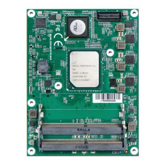
PORTWELL PCOM-B701G User's Guide 1 Introduction The Portwell PCOM-B701G, a Type 7 COM Express basic (125mm x 95mm) module is designed with Intel® Atom® processor product family. Portwell's PCOM-B701G features four 10GbE KR, one GbE, DDR4 ECC/non-ECC memory support, and Gen3 PCIe supporting high speed I/O card. -
Page 11: Block Diagram
COM Express™ PORTWELL PCOM-B701G User's Guide 2 Block Diagram Figure 1 Block Diagram Copyright © PORTWELL 2017 PCOM-B701G User's Guide... -
Page 12: Specifications
COM Express™ PORTWELL PCOM-B701G User's Guide 3 Specifications Table 1 PCOM-B701GVG SPEC Product PCOM-B701G COM Express™ standard pin out Type 7 Rev. 2.1 (Basic 125 x 95mm / 4.92” x 3.74”). Form Factor Processor Intel® Atom-Processor-C3308 ... - Page 13 COM Express™ PORTWELL PCOM-B701G User's Guide 2 x SATA3.0 (6 Gbps) GPIO / I2C / 2 Serial Ports / SMBus Hardware Monitors ITE8380 Embedded Controller, Voltage, Fan and Temperature Power Management ACPI 4.0 Operating Temperature 0 ゚ C ~ 60 ゚ C (processor dependent) Environment ...
-
Page 14: Pcom-B701G Processor List
COM Express™ PORTWELL PCOM-B701G User's Guide 3.1 PCOM-B701G Processor list 3.1 PCOM-B701G Processor list PCOM-B701G Series PCOM-B701G PCOM-B701G - PCOM-B701G - PCOM-B701G - PCOM-B701G Ordering P/N AB1-3G90Z AB1-3G91Z AB1-3G92Z AB1-3G89Z AB1-3H00Z CPU Feature Processor Number C3308 C3508 C3708 C3808 C3958... - Page 15 COM Express™ PORTWELL PCOM-B701G User's Guide PCOM-B701G Series PCOM-B701G PCOM-B701G - PCOM-B701G - PCOM-B701G - PCOM-B701G Ordering P/N AB1-3G90Z AB1-3G91Z AB1-3G92Z AB1-3G89Z AB1-3H00Z Power consumption S0 Idle 100% workload without turbo mode 100% Workload with turbo mode Peak Power Consumption Table 4 PCOM-B701G Processor list Copyright ©...
-
Page 16: Supported Operating Systems
COM Express™ PORTWELL PCOM-B701G User's Guide 3.2 Supported Operating Systems The PCOM-B701GVG supports the following operating systems. Vendor Operating System Supported Microsoft Windows 7 (32/64bit) Windows 8 (32/64bit) Windows 8.1 (32/64bit) Windows 10 (32/64bit) Microsoft Windows 2008 R2 SP1 Microsoft Windows 2012... -
Page 17: Windows Os Driver
COM Express™ PORTWELL PCOM-B701G User's Guide 3.3 Windows OS driver Please download the drivers from Portwell download center website http://www.portwell.tw/support/download_center.php Drivers file name Supported Operating Systems 10GLAN_Win7_64 Windows Server 2008 R2 (64bit) Microsoft Windows 7 (64bit) Chipset_Win7_8_81_32_64 Microsoft Windows 7 (32/64bit) Microsoft Windows 8 (32/64bit) Microsoft Windows 8.1 (32/64bit) -
Page 18: Electrical Characteristics
COM Express™ PORTWELL PCOM-B701G User's Guide 3.4 Electrical Characteristics Input voltage +12VDC (Nominal) RTC Battery Power on mode AT Mode Table 7 Electrical characteristics PCOM-B701G Power sequence Copyright © PORTWELL 2017 PCOM-B701G User's Guide... - Page 19 COM Express™ PORTWELL PCOM-B701G User's Guide Figure 1 Power on sequence Copyright © PORTWELL 2017 PCOM-B701G User's Guide...
- Page 20 COM Express™ PORTWELL PCOM-B701G User's Guide Figure 2 Shutdown sequence Copyright © PORTWELL 2017 PCOM-B701G User's Guide...
-
Page 21: Mechanical Dimensions
COM Express™ PORTWELL PCOM-B701G User's Guide 3.5 Mechanical Dimensions Figure 3 Mechanical Dimensions - Top Copyright © PORTWELL 2017 PCOM-B701G User's Guide... - Page 22 COM Express™ PORTWELL PCOM-B701G User's Guide Figure 4 Mechanical Dimensions - Bottom Copyright © PORTWELL 2017 PCOM-B701G User's Guide...
-
Page 23: Sodimm Socket Design
COM Express™ PORTWELL PCOM-B701G User's Guide Net weight Module .0g +/- 2% Cooler (H/S+FAN) .0g +/- 2% Table 8 Weight 3.6 3 SODIMM socket design PCOM-B701G has designed additional Memory SODIMM socket at the bottom, which supports up to DDR4 48GB capacity. Before inserting the DDR4 SODIMM memory, please refer to below SODIMM arrangement and note that, there are 2 SODIMM socket of channel 0, the CH0 SODIMM1 (the bottom one) works only if CH0 SDDIMM0 (the top one) is inserted. -
Page 24: Ordering Guide
Table 11 Ordering Guide - Accessory PCOM-C700 - PCOM-B701G Evaluation carrier (EVA Board) PCOM-C700 is designed for functions verification of PCOM-B701G, which 10GbE function pin is defined by Portwell. Please contact Portwell for detail PCOM-C700 User's Guide. Copyright © PORTWELL 2017... -
Page 25: Heat Sink / Cooler
COM Express™ PORTWELL PCOM-B701G User's Guide 4 Heat sink / Cooler Heat sink Dimensions Figure 6 Heat sink / cooler mechanical dimensions Copyright © PORTWELL 2017 PCOM-B701G User's Guide... -
Page 26: H/S Assembly Guide
COM Express™ PORTWELL PCOM-B701G User's Guide 4.1 H/S Assembly guide Figure 7 H/S Assembly guide Copyright © PORTWELL 2017 PCOM-B701G User's Guide... -
Page 27: Packaging
COM Express™ PORTWELL PCOM-B701G User's Guide 4.2 Packaging Package Appearance Size Anti-Static bubble bag 180x135mm White Paper Box 210x151x40mm Shipping Box 595x300x195mm (10 pcs White paper box) Copyright © PORTWELL 2017 PCOM-B701G User's Guide... -
Page 28: Signal Descriptions And Pin Out Tables
COM Express™ PORTWELL PCOM-B701G User's Guide 5 Signal Descriptions and Pin out Tables Signal Tables Terminology Descriptions Input to the Module Output from the Module Bi-direction input / output signal Open Drain output CMOS Logic input or output. Input thresholds and output levels shall be 80% of supply rail for high side and 20% of the relevant supply rail for low side. - Page 29 COM Express™ PORTWELL PCOM-B701G User's Guide #Note : Reserved / Not connected pins are highlighted as gray color. Signal Description Type Power / Tolerance PU / PD Note GND(FIXED) GND(FIXED) Gigabit Ethernet Controller 0: GBE0_MDI3- Media Dependent Interface Analog 3.3V max Suspend...
- Page 30 COM Express™ PORTWELL PCOM-B701G User's Guide Gigabit Ethernet Controller 0: GBE0_MDI1+ Media Dependent Interface Analog 3.3V max Suspend Differential Pairs GND(FIXED) GND(FIXED) Gigabit Ethernet Controller 0: GBE0_MDI0- Media Dependent Interface Analog 3.3V max Suspend Differential Pairs Gigabit Ethernet Controller 0:...
- Page 31 COM Express™ PORTWELL PCOM-B701G User's Guide Serial ATA or SAS Channel 0 SATA0_RX- SATA AC coupled on Module receive differential pair. GND(FIXED) GND(FIXED) PCI Express Differential Transmit PCIE_TX15+ PCIE AC coupled on Module Pairs PCI Express Differential Transmit PCIE_TX15- PCIE...
- Page 32 COM Express™ PORTWELL PCOM-B701G User's Guide RSVD Reserved Pin Selection straps to determine the BIOS_DIS0# / BIOS boot device.The Carrier PU 10K CMOS ESPI_SAFS should only float these or pull them ohm to 3.3V low. Shared pin with ESPI_SAFS Active low output indicating that...
- Page 33 COM Express™ PORTWELL PCOM-B701G User's Guide USB over-current sense, USB channels 2 and 3. A pull-up for this PU 10K USB_2_3_OC# line shallbe present on the Module. CMOS 3.3V Suspend / 3.3V ohm to Do not pull this line high on the...
- Page 34 COM Express™ PORTWELL PCOM-B701G User's Guide Pairs General purpose input pins. Pulled PU 10k GPI0 CMOS 3.3V / 3.3V high internally on the Module. ohm to 3.3V PCI Express Differential Transmit PCIE_TX4+ PCIE AC coupled on Module Pairs PCI Express Differential Transmit...
- Page 35 COM Express™ PORTWELL PCOM-B701G User's Guide General purpose input pins. Pulled PU 10k GPI2 CMOS 3.3V / 3.3V high internally on the Module. ohm to 3.3V PCI Express Differential Transmit PCIE_TX0+ PCIE AC coupled on Module Pairs PCI Express Differential Transmit...
- Page 36 COM Express™ PORTWELL PCOM-B701G User's Guide Pairs NCSI Transmit Enable PD 270 NCSI_TX_EN (PD 10K on Carrier when NC-SI is 3.3V Suspend / 3.3V not used on Carrier) General purpose input pins. Pulled PU 10k GPI3 CMOS 3.3V / 3.3V high internally on the Module.
- Page 37 COM Express™ PORTWELL PCOM-B701G User's Guide General purpose output pins. GPO0 Upon a hardware reset, these CMOS 3.3V / 3.3V outputs should be low. SPI_CLK Clock from Module to Carrier SPI CMOS 3.3V Suspend / 3.3V Data out from Module to Carrier...
- Page 38 COM Express™ PORTWELL PCOM-B701G User's Guide LID button. Low active signal used PU 47K to A103 LID# by the ACPI operating system for a CMOS 3.3V Suspend / 12V 3VSB LID switch. Primary power input: +12V A104 VCC_12V +12V nominal.
- Page 39 COM Express™ PORTWELL PCOM-B701G User's Guide LPC multiplexed address, LPC_AD1 / ESPI_IO_1 command and data bus / Shared CMOS 3.3V / 3.3V pin with ESPI IO LPC multiplexed address, LPC_AD2 / ESPI_IO_2 command and data bus / Shared CMOS 3.3V / 3.3V...
- Page 40 COM Express™ PORTWELL PCOM-B701G User's Guide System Management Bus Alert – active low input can be used to PU 4.7k SMB_ALERT# generate an SMI# (System CMOS 3.3V Suspend / 3.3V ohm to Management Interrupt) or to wake 3VSB the system.
- Page 41 COM Express™ PORTWELL PCOM-B701G User's Guide other configurable devices time to be programmed. PCI Express Differential Receive PCIE_RX14+ PCIE AC coupled off Module Pairs PCI Express Differential Receive PCIE_RX14- PCIE AC coupled off Module Pairs Output indicating that a watchdog CMOS 3.3V / 3.3V...
- Page 42 COM Express™ PORTWELL PCOM-B701G User's Guide PCI Express Differential Receive PCIE_RX12+ PCIE AC coupled off Module Pairs PCI Express Differential Receive PCIE_RX12- PCIE AC coupled off Module Pairs GND(FIXED) GND(FIXED) USB differential pairs, channels 3. USB3- All USB ports except USB7, if 3.3V Suspend / 3.3V...
- Page 43 COM Express™ PORTWELL PCOM-B701G User's Guide This signal is used by the Carrier to indicate the operating mode of the LPC/eSPI bus. If pulled down by the Carrier LPC mode is selected. If pulled up or left ESPI_EN CMOS floating, eSPI is selected if available.
- Page 44 COM Express™ PORTWELL PCOM-B701G User's Guide Reset output from Module to Carrier Board. Active low. Issued by Module chipset and mayresult from a low SYS_RESET#input, a PU 1k ohm CB_RESET# low PWR_OKinput, a CMOS 3.3V Suspend / 3.3V to 3VSB...
- Page 45 COM Express™ PORTWELL PCOM-B701G User's Guide Pairs GND(FIXED) GND(FIXED) PCI Express Differential Receive PCIE_RX2+ PCIE AC coupled off Module Pairs PCI Express Differential Receive PCIE_RX2- PCIE AC coupled off Module Pairs General purpose output pins. GPO3 Upon a hardware reset, these CMOS 3.3V / 3.3V...
- Page 46 COM Express™ PORTWELL PCOM-B701G User's Guide PCI Express Differential Receive PCIE_RX8- PCIE AC coupled off Module Pairs PCI Express Differential Receive PCIE_RX9+ PCIE AC coupled off Module Pairs PCI Express Differential Receive PCIE_RX9- PCIE AC coupled off Module Pairs PCI Express Differential Receive...
- Page 47 COM Express™ PORTWELL PCOM-B701G User's Guide Selection straps to determine the BIOS_DIS1# / BIOS boot device.The Carrier PU 10k CMOS ESPI_BBS should only float these or pull them ohm to 3.3V low / Shared pin with ESPI_BBS NCSI_RX_ER NC-SI Receive error 3.3V Suspend / 3.3V...
- Page 48 COM Express™ PORTWELL PCOM-B701G User's Guide Chip select for Carrier Board SPI - SPI_CS# maybe sourced from chipset SPI0 CMOS 3.3V Suspend / 3.3V or SPI1 PD 10k NCSI_ARB_IN NC-SI hardware arbitration input. 3.3V Suspend / 3.3V PU 10K to NCSI_ARB_OUT NC-SI hardware arbitration output.
- Page 49 COM Express™ PORTWELL PCOM-B701G User's Guide Primary power input: +12V B109 VCC_12V +12V nominal. B110 GND(FIXED) GND(FIXED) GND(FIXED) GND(FIXED) Additional transmit signal USB_SSRX0- differential pairs for the PCIE AC coupled off Module SuperSpeed USB data path. Additional transmit signal USB_SSRX0+...
- Page 50 COM Express™ PORTWELL PCOM-B701G User's Guide Additional transmit signal USB_SSRX3- differential pairs for the PCIE AC coupled off Module SuperSpeed USB data path. Additional transmit signal USB_SSRX3+ differential pairs for the PCIE AC coupled off Module SuperSpeed USB data path.
- Page 51 COM Express™ PORTWELL PCOM-B701G User's Guide PCI Express Differential Receive PCIE_RX6+ PCIE AC coupled off Module Pairs PCI Express Differential Receive PCIE_RX6- PCIE AC coupled off Module Pairs GND(FIXED) GND(FIXED) PCI Express Differential Receive PCIE_RX7+ PCIE AC coupled off Module...
- Page 52 COM Express™ PORTWELL PCOM-B701G User's Guide external Optical SFP Module I2C data signal of the 2-wire management interface used by the 10G_SFP_SDA2 10GbE controller to access the 3.3V Suspend / 3.3V management registers of an external Optical SFP Module Output signal that resets an optical...
- Page 53 COM Express™ PORTWELL PCOM-B701G User's Guide external Optical SFP Module I2C data signal of the 2-wire management interface used by the PU 4.7K to 10G_SFP_SDA0 10GbE controller to access the 3.3V Suspend / 3.3V 3VSB management registers of an external Optical SFP Module Software-Definable Pins.
- Page 54 COM Express™ PORTWELL PCOM-B701G User's Guide I/O interface mode clock signal for serial data transfers between the MAC and an external PHY. I2C Mode: I2C clock signal, of the 2-wire management interface used I/O OD 3.3V Suspend / 3.3V for serial data transfers between the MAC and an external PHY.
- Page 55 COM Express™ PORTWELL PCOM-B701G User's Guide Pairs The TYPE pins indicate to the Carrier Board the Pin-out Type TYPE1# that is implemented on the Module. PCI Express Differential Receive PCIE_RX18+ PCIE AC coupled off Module Pairs PCI Express Differential Receive...
- Page 56 COM Express™ PORTWELL PCOM-B701G User's Guide GND(FIXED) GND(FIXED) PCI Express Differential Receive PCIE_RX22+ PCIE AC coupled off Module Pairs PCI Express Differential Receive PCIE_RX22- PCIE AC coupled off Module Pairs PCI Express Differential Receive PCIE_RX23+ PCIE AC coupled off Module...
- Page 57 COM Express™ PORTWELL PCOM-B701G User's Guide PCI Express Differential Receive PCIE_RX27+ PCIE AC coupled off Module Pairs PCI Express Differential Receive PCIE_RX27- PCIE AC coupled off Module Pairs GND(FIXED) GND(FIXED) PCI Express Differential Receive PCIE_RX28+ PCIE AC coupled off Module...
- Page 58 COM Express™ PORTWELL PCOM-B701G User's Guide Primary power input: +12V C104 VCC_12V +12V nominal. Primary power input: +12V C105 VCC_12V +12V nominal. Primary power input: +12V C106 VCC_12V +12V nominal. Primary power input: +12V C107 VCC_12V +12V nominal. Primary power input: +12V...
- Page 59 COM Express™ PORTWELL PCOM-B701G User's Guide Additional transmit signal USB_SSTX1+ differential pairs for the PCIE AC coupled on Module SuperSpeed USB data path. Additional transmit signal USB_SSTX2- differential pairs for the PCIE AC coupled on Module SuperSpeed USB data path.
- Page 60 COM Express™ PORTWELL PCOM-B701G User's Guide MDIO Mode: Management Data I/O interface mode data signal for 3.3V Suspend / 3.3V serial data transfers between the MAC and an external PHY. D16 10G_PHY_MDIO_SDA2 I2C Mode: I2C data signal, of the 2-wire management interface used I/O OD 3.3V Suspend / 3.3V...
- Page 61 COM Express™ PORTWELL PCOM-B701G User's Guide 10GBASE-KR ports, transmit AC coupled on 10G_KR_TX3- output differential pairs. Carrier 10GBASE-KR ports, transmit AC coupled on 10G_KR_TX2+ output differential pairs. Carrier 10GBASE-KR ports, transmit AC coupled on 10G_KR_TX2- output differential pairs. Carrier GND(FIXED)
- Page 62 COM Express™ PORTWELL PCOM-B701G User's Guide Phy mode select pin: If high Phy0 and Phy1 are configured by MDIO. If low Phy2 and Phy3 are 10G_PHY_SEL_01 configured by I2C. For MDIO 3.3V Suspend / 3.3V mode, this pin should be left not connected on the Carrier.
- Page 63 COM Express™ PORTWELL PCOM-B701G User's Guide MDIO Mode: Management Data I/O interface mode data signal for 3.3V Suspend / 3.3V serial data transfers between the MAC and an external PHY. D45 10G_PHY_MDIO_SDA1 I2C Mode: I2C data signal, of the 2-wire management interface used I/O OD 3.3V Suspend / 3.3V...
- Page 64 COM Express™ PORTWELL PCOM-B701G User's Guide Pairs PCI Express Differential Transmit PCIE_TX16- PCIE AC coupled on Module Pairs RSVD Reserved Pin PCI Express Differential Transmit PCIE_TX17+ PCIE AC coupled on Module Pairs PCI Express Differential Transmit PCIE_TX17- PCIE AC coupled on Module...
- Page 65 COM Express™ PORTWELL PCOM-B701G User's Guide PCI Express Differential Transmit PCIE_TX21+ PCIE AC coupled on Module Pairs PCI Express Differential Transmit PCIE_TX21- PCIE AC coupled on Module Pairs GND(FIXED) GND(FIXED) PCI Express Differential Transmit PCIE_TX22+ PCIE AC coupled on Module...
- Page 66 COM Express™ PORTWELL PCOM-B701G User's Guide PCI Express Differential Transmit PCIE_TX26+ PCIE AC coupled on Module Pairs PCI Express Differential Transmit PCIE_TX26- PCIE AC coupled on Module Pairs PCI Express Differential Transmit PCIE_TX27+ PCIE AC coupled on Module Pairs PCI Express Differential Transmit...
- Page 67 COM Express™ PORTWELL PCOM-B701G User's Guide PCI Express Differential Transmit D101 PCIE_TX31+ PCIE AC coupled on Module Pairs PCI Express Differential Transmit D102 PCIE_TX31- PCIE AC coupled on Module Pairs D103 Primary power input: +12V D104 VCC_12V +12V nominal. Primary power input: +12V...
-
Page 68: Bios Setup Items
COM Express™ PORTWELL PCOM-B701G User's Guide 6 BIOS Setup Items PCOM-B701VG is equipped with the AMI BIOS stored in Flash ROM. These BIOS has a built-in Setup program that allows users to modify the basic system configuration easily. This type of information is stored in CMOS RAM so that it is retained during power-off periods. -
Page 69: Entering Setup -- Launch System Setup
COM Express™ PORTWELL PCOM-B701G User's Guide 6.1 Entering Setup -- Launch System Setup Power on the computer and the system will start POST (Power On Self Test) process. When the message below appears on the screen, press <Del> key will enter BIOS setup screen. -
Page 70: Main
COM Express™ PORTWELL PCOM-B701G User's Guide 6.2 Main Figure 8 BIOS MAIN Copyright © PORTWELL 2017 PCOM-B701G User's Guide... -
Page 71: Configuration
COM Express™ PORTWELL PCOM-B701G User's Guide 6.3 Configuration Figure 9 BIOS C ONFIGURATION Copyright © PORTWELL 2017 PCOM-B701G User's Guide... -
Page 72: Cpu
COM Express™ PORTWELL PCOM-B701G User's Guide Figure 12 BIOS CPU Copyright © PORTWELL 2017 PCOM-B701G User's Guide... -
Page 73: Lan
COM Express™ PORTWELL PCOM-B701G User's Guide Figure 13 LAN Copyright © PORTWELL 2017 PCOM-B701G User's Guide... -
Page 74: Pcie
COM Express™ PORTWELL PCOM-B701G User's Guide PCIE Figure 14 PCIE Copyright © PORTWELL 2017 PCOM-B701G User's Guide... -
Page 75: Sata
COM Express™ PORTWELL PCOM-B701G User's Guide SATA Figure 15 BIOS SATA Copyright © PORTWELL 2017 PCOM-B701G User's Guide... -
Page 76: Usb
COM Express™ PORTWELL PCOM-B701G User's Guide Figure 16 BIOS USB Copyright © PORTWELL 2017 PCOM-B701G User's Guide... -
Page 77: Power Control
COM Express™ PORTWELL PCOM-B701G User's Guide Power control Figure 17 BIOS POWER CONTROL Copyright © PORTWELL 2017 PCOM-B701G User's Guide... -
Page 78: Tpm
COM Express™ PORTWELL PCOM-B701G User's Guide Figure 18 BIOS TPM Copyright © PORTWELL 2017 PCOM-B701G User's Guide... -
Page 79: Super Io
COM Express™ PORTWELL PCOM-B701G User's Guide Super IO Figure 19 BIOS SUPER IO Copyright © PORTWELL 2017 PCOM-B701G User's Guide... -
Page 80: Hw Monitor
COM Express™ PORTWELL PCOM-B701G User's Guide HW Monitor Figure 20 BIOS HW MONITOR Copyright © PORTWELL 2017 PCOM-B701G User's Guide... -
Page 81: Serial Port
COM Express™ PORTWELL PCOM-B701G User's Guide Serial Port Figure 21 BIOS SERIAL PORT Copyright © PORTWELL 2017 PCOM-B701G User's Guide... -
Page 82: Security
COM Express™ PORTWELL PCOM-B701G User's Guide Security Figure 22 BIOS Security Copyright © PORTWELL 2017 PCOM-B701G User's Guide... -
Page 83: Boot
COM Express™ PORTWELL PCOM-B701G User's Guide 6.4 Boot Figure 23 BIOS BOOT Copyright © PORTWELL 2017 PCOM-B701G User's Guide... -
Page 84: Event Logs
COM Express™ PORTWELL PCOM-B701G User's Guide Event Logs Figure 24 BIOS Event Logs Copyright © PORTWELL 2017 PCOM-B701G User's Guide... -
Page 85: Save & Exit
COM Express™ PORTWELL PCOM-B701G User's Guide Save & Exit Figure 25 BIOS SAVE & EXIT Copyright © PORTWELL 2017 PCOM-B701G User's Guide... -
Page 86: System Resources
COM Express™ PORTWELL PCOM-B701G User's Guide 7 System Resources Device I/O Address Note Embedded Controller (ITE8528) 0x6E / 0x6F EC Address 0x62 / 0x66 EC ACPI CMD Port 0x200 / 0x201 EC BRAM Port for I2C function 0x1300~0x13FF EC LPC IO Space... -
Page 87: Bios Update
COM Express™ PORTWELL PCOM-B701G User's Guide 8 BIOS Update BIOS/EC DOS Update SOP process Step 1. Create a DOS USB DOK. (Must be FAT or FAT32 format) Step 2. Unzip update file to the DOS USB DOK. Copyright © PORTWELL 2017... - Page 88 COM Express™ PORTWELL PCOM-B701G User's Guide Step 3. Plug the DOS USB DOK into the target system and boot from the DOS USB DOK. Step 4. Under the update file folder, type command : "update" and press enter. Copyright © PORTWELL 2017...
- Page 89 COM Express™ PORTWELL PCOM-B701G User's Guide Step 5. The update process will start and you can see the updating progress. Once finished, please power off and restart the system. <End of BIOS/EC DOS update process> Copyright © PORTWELL 2017 PCOM-B701G User's Guide...
- Page 90 COM Express™ PORTWELL PCOM-B701G User's Guide BIOS/EC UEFI Update SOP process Step 1. Prepare a USB DOK. (Must be FAT or FAT32 format) Step 2. Unzip update file to the USB DOK. Copyright © PORTWELL 2017 PCOM-B701G User's Guide...
- Page 91 COM Express™ PORTWELL PCOM-B701G User's Guide Step 3. Select UEFI boot mode in the BIOS boot menu and save, then restart the system. Copyright © PORTWELL 2017 PCOM-B701G User's Guide...
- Page 92 COM Express™ PORTWELL PCOM-B701G User's Guide Step 4. Plug the USB DOK into the target system and boot from UEFI Shell. Copyright © PORTWELL 2017 PCOM-B701G User's Guide...
- Page 93 COM Express™ PORTWELL PCOM-B701G User's Guide Step 5. Under the UEFI shell, direct to your USB DOK, below is an example uses fs0. Then direct to the folder with updated file and type command : "update" and press enter. Copyright © PORTWELL 2017...
- Page 94 COM Express™ PORTWELL PCOM-B701G User's Guide Step 6. The updating process will start and you can see the updating progress. Once finished, please power off and restart the system. <End of BIOS/EC UEFI update process> Copyright © PORTWELL 2017 PCOM-B701G User's Guide...
-
Page 95: Portwell Software Tool
Windows and Linux OS. For more information please contact PORTWELL. PORTWELL BIOS web Tool (PBT) The PORTWELL BIOS web Tool (PBT) is a brand new on-line utility innovated by PORTWELL. PBT now is available for PORTWELL's premiere customers who are able to... -
Page 96: Industry Specifications
COM Express™ PORTWELL PCOM-B701G User's Guide 10 Industry Specifications The list below provides links to industry specifications that apply to PORTWELL modules. Low Pin Count Interface Specification, Revision 1.0 (LPC) http://www.intel.com/design/chipsets/industry/lpc.htm Universal Serial Bus (USB) Specification, Revision 2.0 http://www.usb.org/home PCI Specification, Revision 2.3 https://www.pcisig.com/specifications...
Need help?
Do you have a question about the COM Express PCOM-B701G and is the answer not in the manual?
Questions and answers