Table of Contents
Advertisement
Available languages
Available languages
Quick Links
MANUALE D'USO E MANUTENZIONE
USER'S MANUAL
BEDIENUNGS - UND WARTUNGSHANDBUCH
MANUEL D'UTILISATION ET D'ENTRETIEN
NAVODILA ZA UPORABO
BEDIENINGS- EN ONDERHOUDSHANDLEIDING
PN 120
Via G.Pastore, 8 | Zona industriale | 42045 Luzzara (RE) | Italy | (t) +39 0522 977169 | (f) +39 0522 977819 |
(m) info@eurosystems-spa.com | (w) www.eurosystems-spa.com
Advertisement
Chapters
Table of Contents

Related Manuals for Eurosystems PN 120


Summary of Contents for Eurosystems PN 120
- Page 1 MANUEL D’UTILISATION ET D’ENTRETIEN NAVODILA ZA UPORABO BEDIENINGS- EN ONDERHOUDSHANDLEIDING PN 120 Via G.Pastore, 8 | Zona industriale | 42045 Luzzara (RE) | Italy | (t) +39 0522 977169 | (f) +39 0522 977819 | (m) info@eurosystems-spa.com | (w) www.eurosystems-spa.com...
- Page 3 ITALIANO - Lingua originale ENGLISH - Translation of the original DEUTSCH - Übersetzung aus dem Originalen FRANÇAIS - Traduction du original SLOVENSKI - Prevod izvirnika NEDERLANDS - Vertaling van het origineel...
- Page 4 IMMAGINI | PICTURES | ABBILDUNGEN | IMAGES | SLIKE | AFBEELDINGEN [ fig. 01 ] 53 kg [ fig. 02 ] [ fig. 03 ]...
- Page 5 [ fig. 04 ] [ fig. 05 ] [ fig. 06] [ fig. 07 ]...
- Page 6 [ fig. 08] [ fig. 09 ]...
- Page 7 [ fig. 09A] [ fig. 10 ]...
- Page 8 [ fig. 10A ] [ fig. 11]...
-
Page 9: Table Of Contents
1. SOMMARIO 5. Istruzioni d’uso IT-08 5.1. Completamento montaggio IT-08 1. Informazioni generali 5.1.A. Fissaggio tubo di IT-02 1.1. Introduzione prolunga IT-02 IT-09 1.2. Come leggere il manuale 5.1.B. Montaggio zavorra IT-02 IT-09 1.3. Conservazione del manuale 5.2. Aggancio attrezzo IT-02 IT-09 1.4. -
Page 10: Informazioni Generali
Le nostre macchine, prima di essere proprietà di Eurosystems Spa e non fabbricate in serie, vengono collaudate possono essere riprodotti in alcun modo, in maniera molto rigorosa e, durante né... -
Page 11: Designazione Delle Parti
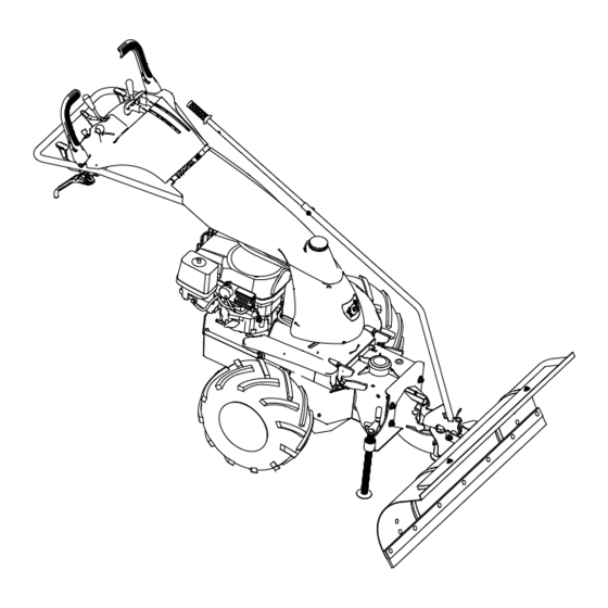
8. Zavorra: 1.5. DESCRIZIONE E CAMPO DI Il cliente è tenuto a comunicare a Eurosystems Spa i dati relativi al nuovo UTILIZZO proprietario della macchina al fine di poter agevolare gli scambi di informazioni Pala da neve con larghezza di lavoro tra le parti e gli aggiornamenti di questo 120cm, inclinabile di 30°... -
Page 12: Informazioni Generali
“Descrizione a Eurosystems Deutschland campo di utilizzo” è da ritenersi improprio Handelsgesellschaft mbH e non ammesso, per cui Eurosystems Spa Im Fuchshau 14, D-73635 Rudersberg non può essere considerata responsabile. Tel. : +49 7183 30590-0 Fax. : +49 7183 30590-20 1.7. -
Page 13: Macchina
1.9. SIMBOLOGIA UTILIZZATA NEL Si definisce attrezzo una applicazione MANUALE priva di qualsiasi organo in movimento. Sono ad esempio attrezzi la pala da neve PERICOLO! e la vasca di trasporto materiale. Questo simbolo evidenzia tutti i paragrafi, in questo manuale d’uso e manutenzione, possono influenzare Vostra... -
Page 14: Area Di Lavoro E Zona
2.1. AREA DI LAVORO E ZONA DI 2.2. ABBIGLIAMENTO PERICOLO [ fig. 02 ] Durante il lavoro si OBBLIGA ad usare L’utilizzatore è responsabile della sempre scarpe antiinfortunistiche, guanti, sicurezza delle persone, delle cose o e ortoprotettori con attenuazione sonora degli animali, che si trovano all’interno di almeno 20dB. -
Page 15: Spiegazioni Dei Segni Di Pericolo E Delle Etichette Presenti Sull'accessorio/Attrezzo
2.3. SPIEGAZIONI DEI SEGNI DI PERI- 3. Ingombro massimo accessorio: COLO E DELLE ETICHETTE PRESENTI 120x161xH135 cm. SULL’ACCESSORIO [ fig. 01 ] 4. Peso: a. Netto: 51 kg b. Lordo: 53 kg 4. INDICAZIONI PER LA Attenzione! MOVIMENTAZIONE DELL’IMBALLO E DELLA MACCHINA PERICOLO! Per tutte le operazioni di movimentazio-... -
Page 16: Sollevamento
sul fondo; Agganciare come indicato in [15 , fig. 01] 4.3. SOLLEVAMENTO [ fig. 01 ] 4.4. MOVIMENTAZIONE PERICOLO! Spostare l’accessorio solamente quando Utilizzare solo sistemi, organi è attaccato alla macchina P130. strumenti idonei sollevamento di masse pari o superiori a quanto Se in possesso di furgone con gru di indicato nel capitolo “Specifiche della sollevamento, seguire le istruzioni per... -
Page 17: Fissaggio Tubo Di
5.2. AGGANCIO ATTREZZO/ inserire la leva all’interno delle due staffe (22) sulla pala (4) facendo attenzio- ACCESSORIO [ fig. 09, 09A, 10 e 10A] ne che l’estremità ad uncino della molla (15) sia agganciata come in figura. L’accessorio deve essere a terra, orizzon- Aggiungere la vite [16] con rondella (17) tale: e bloccare con altra rondella e dado (18). -
Page 18: Sgancio Attrezzo
5.3. SGANCIO ATTREZZO/ come mostrato in [ fig. 10A ] ACCESSORIO [ fig. 09, 09A, 10 e 10A] ATTENZIONE! • Spegnere il motore della macchina; Prima di avviare la macchina control- lare che il collegamento macchina-ac- • Assicurarsi che la leva PTO (22) sia cessorio sia avvenuto correttamente nella posizione di neutro seguendo la seguente procedura:... -
Page 19: Di Lavoro
dispositivi di sicurezza o dei carter La regolazione dell’altezza della pala si ottiene allentando i quattro dadi (21). di protezione, interrompere tutte le Spostare le slitte (6) in alto o in basso fino operazioni. a raggiungere l’altezza desiderata, in base 5.7. -
Page 20: Pulizia Durante La Giornata
PERICOLO! PERICOLO! In caso di danneggiamento all’attrezzo, pulire utilizzare strumenti all’accessorio o alla macchina spegnere appropriati a seconda della tipologia immediatamente il motore. attrezzo/accessorio utilizzando. Prestare attenzione ad Per descrizioni specifiche dei relativi elementi taglienti. comandi fare riferimento al capitolo “Uso” e “Comandi della macchina”... -
Page 21: Programma Di Manutenzione
Utilizzare solo parti di ricambio originali Eurosystems. Tutti altri ricambi commerciali devono corrispondere ai requisiti tecnici e di qualità specificati da Eurosystems. 6.1. PROGRAMMA DI MANUTENZIONE DELL’ACCESSORIO... -
Page 22: Ingrassaggio
6.3. INGRASSAGGIO [ fig. 11] Ogni 25÷30 ore di lavoro ingrassare i perni di oscillazione/rotazione tramite gli ingrassatori (29). 6.4. SOSTITUZIONE DELLA LAMA RASCHIATRICE Rivolgersi ad un rivenditore autorizzato Eurosystems. IT-14... -
Page 23: Guasti
ALTEZZA appoggiate al terreno LAVORO” OSCILLAZIO- Mancanza di Ingrassare il perno NE DELLA grasso nel perno Vedi paragrafo orizzontale di PALA BLOC- orizzontale di “INGRASSAGGIO” oscillazione CATA oscillazione * - Rivolgersi ad un rivenditore autorizzato Eurosystems; U - Utilizzatore IT-15... -
Page 24: Istruzioni Supplementari
9. ISTRUZIONI SUPPLEMENTARI in modo appropriato al termine del suo ciclo di vita. 9.1. SMALTIMENTO Chiedere informazioni alle autorità locali in merito alle zone dedicate allo smaltimento Il prodotto al termine del suo ciclo di dei rifiuti. vita deve essere smaltito seguendo le norme vigenti relative allo smaltimento Chi non smaltisce il prodotto seguendo Differenziato e non può... - Page 25 TABLE OF CONTENTS 5.3. Uncoupling the tool/accessory EN-10 5.4. Working height 1. General information adjustments EN-02 EN-10 1.1. Introduction 5.5. Inclination adjustment EN-02 EN-10 1.2. How to read the manual 5.6. Preliminary checks to be made EN-02 1.3. Storage of the manual each time before starting EN-02 1.4.
-
Page 26: General Information
Following the present technical nature and belong as a strict instructions carefully and you will have the property to Eurosystems spa and can not satisfaction of possessing a machine that be reproduced either partially or com- properly works for a long time to come. -
Page 27: Designation Of Parts
In all cases, all of this is subject to proper 4. Shovel usage and careful maintenance. 5. Shovel coupling 6. Slides 1.7. GENERAL INFORMATION 7. Scraper plate 8. Ballast Only use genuine Eurosystems parts. The user loses all warranty rights in case of use of non-genuine parts. EN-3... -
Page 28: Manufacturer And Machine Data
3. Serial number - Progressive DATA 4. Year of construction 5. Weight Manufacturer: 6. Working widht Eurosystems Spa Via G.Pastore, 8 zona industriale 1.9. SYMBOLS USED IN THE MANUAL 42045 Luzzara (RE) - Italy DANGER! Tel.:+39 0522 977169 Fax:+39 0522 977819 This symbol shows all the paragraphs in Mail: info@eurosystems-spa.com... -
Page 29: Definitions
1.10. DEFINITIONS 2.1. WORKING AREA AND DANGER ZONE An accessory is defined as a tool to whi- ch the machine transmits a motion by me- The user is responsible for the safety of ans of a power take off (PTO) or another people, property and animals that are in- device. -
Page 30: Clothing
2.2. CLOTHING 2.3. EXPLANATIONS OF HAZARD SIGNS AND LABELS ON THE ACCESSORY/ During the work operator MUST always TOOL [ fig. 01] wear safety footwear, gloves and ear pro- tections. The customer or employer operator is exclusively responsible for sourcing this Attention! personal protection devices. -
Page 31: Accessory Specifications
3. ACCESSORY SPECIFICATIONS How to remove it from the packaging: • Cut or tear the cardboard at the 1. Package dimensions: 122x59xH49 base of the pallet and remove it com- (cm.) pletely by raising it; 2. Accessory dimensions: (min.) • Cut any ties on the bottom; 120x115xH115 (cm.) 3. -
Page 32: Handling
Lift the accessory using a hoist or similar lever (5) as shown. tool with minimum capacity compatible [ fig. 05] Enter the lever inside the two with the data indicated in the chapter brackets (22) on the blade (4) making sure “Accessory specifications”. - Page 33 5.2. ATTACHING THE TOOL/ CARE! ACCESSORY [ fig. 09, 09A, 10 and 10A] Before starting the machine, check if the machine-accessory connection has The accessory must be on the ground, ho- been carried out correctly by following the procedure below: rizontal : •...
-
Page 34: Inclination Adjustment
5.3. TOOL/ACCESSORY until you get the requested height accor- UNCOUPLING [ fig. 09, 09A, 10 and 10A] ding to the working needs. Then screw the nuts back again [21]. • Switch the machine’s engine off. • Make sure that the PTO lever [22] is 5.5. -
Page 35: Use
erations. chine gets damaged, immediately turn off the engine. 5.7. USE For specific descriptions of the respecti- ve commands refer to chapter “Use” and DANGER! Always use the personal protection de- “Operating commands” in the machine’s vices required in the paragraph “Cloth- operation and maintenance manual. -
Page 36: Maintenance
Always wear gloves, safety footwear, glasses and use adequate work equip- ment during maintenance of knives and/or other sharp parts. Only use genuine Eurosystems parts. All the other commercial parts must corre- spond to the technical and quality specifi- cations determined by Eurosystems. -
Page 37: Maintenance Plan
6.1. MAINTENANCE PLAN When What Reference Accessory operation After each Operator Cleaning and maintenance manual “CLEANING” paragraph Every 25-30 Lubricate the oscillation/rota- Instructions service/ booklet for working Operator tion pins tool/accessory par. “GREASING” hours 6.2. CLEANING AND WASHING Clean and wash the accessory/tool after each use. -
Page 38: Greasing
Every 25-30 hours working hours grease the oscillation/rotation pins using the gre- asers [29]. 6.4. REPLACING OF THE RUBBER STRIP Please contact an authorized eurosystems dealer. 7. STORAGE CARE! Park the accessory/tool (with or without the connected machine) on stable ground. -
Page 39: Faults
“Height work ground the ground. adjustment“ Lack of grease Please look Oscillation of the Grease the oscillation into the oscillation at chap. shovel id blocked horizontal pivot horizontal pivot “Greasing” AD - Authorized Eurosystems Dealer; U - User EN-15... -
Page 40: Additional Instructions
9. ADDITIONAL INSTRUCTIONS Ask your local authorities for information about the areas dedicated to waste dis- 9.1. DISPOSAL posal. At the end of its life cycle the product must People who do not dispose of the product be disposed of following the sorted dis- according to what is indicated in this par- posal regulations currently in force and it agraph will be responsible for it under the... - Page 41 1. INHALTSANGABE 4.3. Anheben DE-08 4.4. Umgang DE-09 1. Allgemeine Informationen 5. Bedienungsanleitung DE-02 DE-09 1.1. Einleitung 5.1. Fertigstellung der Montage DE-02 DE-09 1.2. Verwendung des Handbuchs 5.1.A. Befestigung DE-02 1.3. Aufbewahrung des Handbuchs Verlängerungsrohr DE-02 DE-09 1.4. Übersicht der Teile 5.1.B.
-
Page 42: Allgemeine Informationen
Angaben vorbe- Folgen Sie aufmerksam diesen Ratschläg- halten technischer Natur, ausschließliches en und Hinweisen und Sie werden über Eigentum der Eurosystems Spa und dür- lange Zeit eine Maschine nutzen können, fen in keiner Weise vervielfältigt werden. die erwartungsgemäß funktioniert. -
Page 43: Übersicht Der Teile
1.5. BESCHREIBUNG UND ereignen, begleiten. Der Kunde ist verpflichtet, der Eurosystems ANWENDUNGSBEREICH Spa entsprechende Angaben für den neu- en Besitzer der Maschine mitzuteilen, um Schneeräumschild mit einer Arbeitsbrei- den Informationsaustausch zwischen den te von 120 cm, schwenkbar bis 30° nach... -
Page 44: Allgemeine Informationen
Verwendung ist als unangemes- Eurosystems Deutschland sen und nicht erlaubt zu betrachten, für Handelsgesellschaft mbH die Eurosystems S.p.A. nicht verantwort Im Fuchshau 14, D-73635 Rudersberg -lich gemacht werden kann. Tel. : +49 7183 30590-0 Fax. : +49 7183 30590-20 1.7. -
Page 45: Im Handbuch Verwendete
1.9. IM HANDBUCH VERWENDETE - und nicht angetriebene Anbaugeräte, SYMBOLE zum Beispiel das Schneeräumschild und der Anbau-Schubkarren. GEFAHR! Dieses Symbol kennzeichnet alle Ab- schnitte in diesem Bedienungs- und War- 2. SICHERHEITSHINWEISE tungshandbuch, die Ihre Sicherheit beein- GEFAHR! trächtigen und tödliche und/oder schwere Vor Montage und Inbetriebnahme der Verletzungen für den Anwender zur Folge Maschine muss dieses Bedienungs-und... -
Page 46: Kleidung
sich im Inneren des Gefahrenbereichs der den Boden und den umliegenden Bereich Maschine aufhalten, verantwortlich. achten. Unter diesem Bereich versteht sich der 2.2. KLEIDUNG Abstand mit einem Radius von 10m, aus- gehend von der Mitte des Anbaugeräts, Während der Arbeit MÜSSEN immer Si- welches an der Maschine angebracht ist cherheitsschuhe, Schutzhandschuhe und [ Abb. -
Page 47: Beschreibungen Der An Dem Schneeräumschild Angebrachten Gefahrenzeichen Und Etiketten
2.3. BESCHREIBUNGEN DER SCHNEERÄUMSCHILDS AN DEM SCHNEERÄUMSCHILD ANGEBRACHTEN GEFAHRENZEICHEN 1. Abmessungen der Verpackung: UND ETIKETTEN [ Abb. 01] 122 x 59 x H 49 cm 2. Abmessungen des Schneeräums- childs mind.: 120 x 115 x 115 cm 3. Abmessungen des Schneeräums- childs max.: 120 x 161 x 135 cm 4. -
Page 48: Schneeräumschilds
SCHNEERÄUMSCHILDS igungen, auch nur teilweise, müssen diese ausgetauscht werden. Die Maschine wird verpackt geliefert, es ACHTUNG! sei denn, es wurden anderweitige Verein- barungen getroffen. Die Maschine niemals mit montiertem Vorgang zum Auspacken der Maschine: Zubehörteil oder Anbaugerät anheben. • Den Karton am Boden auf der Palette aufschneiden oder aufreißen und durch Zum Anheben des Schneeräumschilds Anheben entfernen. -
Page 49: Fertigstellung Der Montage
VERLÄNGERUNGSROHR [ Abb. 07] GEFAHR! Vor Verwendung der Maschine dieses Verlängerungsrohr [14] Bedienungs- und Wartungshandbuch Schwenkrohr [5] einführen und mit der und das Bedienungs- und Wartungshan- Schraube [23], Unterlegsscheibe [24] und dbuch der Maschine P 130 vollständig Mutter [21] montieren. Es besteht die Mög- lesen und verstehen. - Page 50 • Die Antriebsbremse durch umstellen drücken und den Bedienhebel für des Hebels [ 25, Abb. 09A] in die Posi- Zapfwelle [22] betätigen, indem tion lösen ; man ihn in Arbeitsstellung verrie- • Den Hebel [26] in die Position gelt; stellen [Abb.
-
Page 51: Arbeitshöheneinstellung
• Sicherstellen, dass der Bedienhebel sschilds einzustellen, indem man die vier für Zapfwelle (PTO) [22] in neutraler Muttern (21) löst. Die Gleitkufen (6) nach Position steht; oben oder unten verschieben bis sie die • Die Feststellbremse durch umstellen gewünschte Höhe gemäß Ihren Arbeitsan- des Hebels [25] in die Position forderungen erreicht haben. -
Page 52: Anwendung
Im Falle von schadhaften Bauteilen bei und/oder der Zündstecker entfernt wer- der Überprüfung der Sicherheitsvor- den. richtungen oder Schutzgehäuse müs- sen alle Mäharbeiten unverzüglich ein- GEFAHR! gestellt werden. Im Falle eines Schadens am Anbauge- rät, am Zubehörteil oder an der Maschi- 5.7. - Page 53 Anbaugeräts/Zubehörs. an tragenden und sicherheitsrelevanten Achten scharfe Bauteile. Bauteilen durchführen. Verletzungsgefahr! Nur originale Ersatzteile von Eurosystems verwenden. Alle anderen handelsüblichen 6. WARTUNG Ersatzteile müssen den von Eurosystems angeführten, technischen und qualitativen Sowie die Sicherheits- und Betriebshin- Anforderungen entsprechen. weise zu beachten sind, ist es auch wich- 6.1.
-
Page 54: Reinigung
Wann Bezug Bedienungs-und Wartungshan- Nach jeder Schneeräumschilds Bediener Reinigung dbuch Anwendung Abschnitt “REINIGUNG” Bedienungs- und Wartung- Alle 25 – 30 Be- Drehachsen schmie- Bediener shandbuch Schneeräumschild [ 29, Abb. 11] triebsstunden Abschnitt “SCHMIERUNG” 6.2. REINIGUNG UND NASSREINIGUNG Nach jeder Anwendung muss man das Schneeräumschild reinigen und waschen. -
Page 55: Schmierung
sen ist oder sich in der Nähe der Ma- ACHTUNG! schine P 130 befindet. Der Druck kann das elektrische System der Maschine Das Schneeräumschild (mit oder ohne P 130 beschädigen. Übermäßigen Was- angeschlossener Maschine) auf stabi- serverbrauch oder die Verwendung von lem Boden parken. -
Page 56: Zusätzliche Hinweise
MÖGLICHE PROBLEM ABHILFE VERWEIS URSACHEN Schmierfett-Mangel die senkrechte siehe Abschnitt an der senkrechten Drehachse schmieren “SCHMIERUNG” [ 29, Abb. 11] Drehachse mit einem Hebel den Blockierung Verformung / Verstellhebel aus der der Seitenver- Blockierung der Rastung lösen. Falls die stellung des Verstellstange Stange beschädigt ist, Schneeräums-... -
Page 57: Entsorgung
Ende seiner Lebensdauer sachgemäß ent- 9.1 ENTSORGUNG sorgt werden muss. Holen Sie sich bei den örtlichen Behörden Das Produkt muss am Ende seiner Le- die erforderlichen Informationen hinsicht- bensdauer gemäß den geltenden Richt- lich der Abfallentsorgung ein. linien hinsichtlich Abfalltrennung und nicht zusammen mit dem normalen Eine nicht diesen Hinweisen entsprech- Hausmüll entsorgt werden. - Page 59 5.1.A. Fixage du tuyau de prolonge 1. SOMMAIRE FR-09 5.1.B. Montage de la masse FR-09 5.2. Accrochage de l’outil/accessoire 1. Informations générales FR-02 FR-09 5.3. Décrochage de l’outil/accessoire 1.1. Introduction FR-10 FR-02 5.4. Réglage de la hauteur 1.2. Comment lire le manuel FR-02 de travail 1.3.
-
Page 60: Informations Générales
; ils sont de rez jouir d’une machine fonctionnant par- la propriété exclusive d’Eurosystems Spa faitement pendant longtemps. et ne peuvent être reproduites d’aucune Avant d’être fabriquées en série, nos ma- façon, ni partiellement ni entièrement. -
Page 61: Désignation Des Parties
P130). L’outil peut sement conservé en le manipulant avec être utilisé seulement avec la machine mo- attention, sans le toucher avec des mains dèle P130 de production de Eurosystems sales et sans le déposer sur des surfaces spa. souillées. -
Page 62: Machine
Utiliser uniquement des pièces de re- pourrez trouver sur l’étiquette CE apposée change d’origine d’Eurosystems. L’utilisa- sous le guidon [12, fig. 01 ] teur perdra tout droit en garantie dans le cas d’utilisation de pièces de rechange... -
Page 63: Définitions
ATTENTION! Cet accessoire répond à toutes les Ce symbole indique les situations qui normes européennes en vigueur pendant peuvent provoquer des lésions légères la période de production. Malgré cela, à l’utilisateur et / ou des dommages à la une utilisation inappropriée ou un mau- machine. -
Page 64: Habillement
pas permis de rester dans le périmètre de danger pour quelque raison que ce soit. Seul l’utilisateur ayant lu et compris le ma- nuel intégralement est autorisé à rester à l’intérieur d’un tel périmètre et à occuper Par ailleurs, il est conseillé d’utiliser des le poste d’opération derrière le guidon en lunettes de sécurité... -
Page 65: Spécifications De L'accessoire
4. INDICATIONS POUR LA MANUTEN- TION DE L’EMBALLAGE ET DE LA MA- CHINE [10] DANGER! Pour toutes les opérations de déplace- ment, toujours porter des chaussures de sécurité et des gants. 4.1. DEPLACEMENT DE Attention! Utiliser les crochets de L’EMBALLAGE [ fig. -
Page 66: Levage
4.3. LEVAGE [ fig. 01 ] 01 ] (crochets). 4.4. MANUTENTION DANGER! Utiliser seulement les systèmes, or- ganes et instruments convenant au sou- Déplacer l’outil seulement quand il est ac- lèvement de masses égales ou supé- croché à la machine P130. rieures à... -
Page 67: Fixage Du Tuyau De Prolonge
5.2. ENCLENCHEMENT OUTIL / ACCES- à crochet du ressort (15) soit accroché comme indiqué dans la figure. SOIRE [ fig. 09, 09A, 10 et 10A ] Rajouter la vis (16) avec la rondelle (17) et bloquer avec une autre rondelle et écrou L’accessoire doit être au sol, horizontal : (18). -
Page 68: De Travail
ATTENTION! 5.3. DECONNECTER L’OUTIL / L’ACCES- Avant de démarrer la machine, vérifiez SOIRE [ fig. 09, 09A, 10 et 10A ] que la jonction machine-accessoire a été effectuée correctement suivant la • Éteindre le moteur de la machine, procédure: • S’assurer que le levier PTO [22] soit •... - Page 69 On peut régler la hauteur de la lame des- tifs de sécurité ou des carters de pro- serrant les 4 écrous (21). Déplacer les pa- tection, interrompre toutes les opéra- tins (6) en haut ou en bas jusqu’à la hau- tions.
-
Page 70: Entretien
DANGER! DANGER! Si l’outil, l’accessoire ou la machine est Pour nettoyer, utilisez les outils appro- endommagé, éteindre immédiatement priés en fonction du type d’outil / ac- le moteur. cessoire que vous utilisez. Faites atten- tion aux éléments tranchants. Pour des descriptions spécifiques des commandes respectives, consulter le chapitre «... - Page 71 çages, des débridages, etc. sur des élé- ments structuraux et des dispositifs de sécurité. Utiliser uniquement des pièces de re- change d’origine d’Eurosystems. Toutes les autres pièces de rechanges commer- ciales correspondent aux conditions re- quises techniques et de qualité spécifiées par Eurosystems.
-
Page 72: Graissage
7. ENTREPOSAGE outil en utilisant de l‘air comprimé ATTENTION! ATTENTION! Ne retirer en aucun cas les coffres de Garer l‘accessoire / outil (avec ou sans machine branchée) sur des terrains sta- protection présents sur la machine. bles. Lavage : Entreposage à court ou à long terme : Laver soigneusement les surfaces sales de neige/ boues/herbe etc…... -
Page 73: Pannes
MANQUE DE OSCILLATION GRAISSE DANS GRAISSER L’AXE HORI- VOIR CHAPI- DE LA LAME BLO- L’AXE HORIZON- ZONTALE D’OSCILLA- TRE “GRAIS- QUEE TALE D’OSCILLA- TION SAGE” TION * - S’adresser à un détaillant agréé par Eurosystems ; U - Utilisateur FR-15... -
Page 74: Instructions Supplémentaires
9. INSTRUCTIONS SUPPLEMENTAIRES priée à la fin de son cycle de vie. 9.1. DEMANTELEMENT Demander des informations aux autorités locales sur les zones dédiées à l’élimina- Au terme de son cycle de vie, le produit doit tion des déchets. être éliminé conformément aux normes en vigueur relatives à... - Page 75 1. KAZALO 5.4. Nastavitev višine dela SL-09 5.5. Nastavitev nagiba SL-10 1. Splošne informacije 5.6. Predhodni pregledi, ki jih je treba SL-02 1.1. Uvod opraviti pred vsakim SL-02 1.2. Kako prebirati ta navodila zagonom stroja SL-10 SL-02 1.3. Shranjevanje navodil 5.7.
-
Page 76: Kazalo
Eurosystems, Spa, in jih kot takšne ni kot bi moral, in bo deloval še dolgo časa. dovoljeno razmnoževati deloma ali v celoti. Pred množično proizvodnjo so naše... -
Page 77: Oznake Delov
Vsaka druga uporaba, ki ni navedena v 5. Priključek lopate odstavku “Opis in področje uporabe”, 6. Sani se šteje za neustrezno in ni dovoljena; 7. Strgalna plošča Eurosystems, S. p. a., zanjo ni odgovoren. 8. Balast 1.7. SPLOŠNA NAVODILA 1.5. OPIS IN PODROČJE UPORABE Uporabljajte originalne dele Snežna lopata z delovno širino 120 cm, z... -
Page 78: Podatki Proizvajalca Stroja
1.8 PODATKI PROIZVAJALCA STROJA Proizvajalec: 1. Proizvajalec Eurosystems, Spa 2. Tip Via G.Pastore, 8 zona industriale 3. Serijska številka – naraščajoče 42045 Luzzara (RE) – Italija 4. Leto izdelave Tel. št.: +39 0522 977169 5. -
Page 79: Definicije
INFORMACIJA: 2.1. DELOVNA POVRŠINA IN OBMOČJE Simbol kaže na posebno označevanje za TVEGANJA [ sl. 02 ] večjo jasnost in lažjo uporabo. Uporabnik je odgovoren za varnost ljudi, 1.10. DEFINICIJE lastnine in živali, ki so v nevarnem območju okoli stroja. Dodatna oprema je opredeljena kot aplikacija, s katero naprava s pomočjo To območje je definirano kot območje z... -
Page 80: Obrazložitev Simbolov Za Nevarnosti In Etiket Na Pripomočku/Stroju
2.2. OBLEKA [10] Med delom MORATE vedno nositi zaščitno obutev, rokavice in zaščito za ušesa z dušenjem zvoka ali vsaj 20dB. Izključno kupec ali operator stroja je odgovoren za pridobitev teh osebnih zaščitnih pripomočkov. Pozor! dvigovanju uporabljajte rokavice in sledite navodilom iz tega priročnika. -
Page 81: Premik Embalaže
4.1. PREMIK EMBALAŽE PAZITE! [sl. 03 ] Ne uporabljajte sistemov ali naprav za dvigovanje, ki imajo ostre dele. odstranitev pakiranja uporabite viličarja kot je prikazano na [ sl. 03 ]. Teža NEVARNOST! pakiranja stroja je opredeljena v odstavku Pred dvigovanjem preverite kako z naslovom »Specifikacije stroja«. -
Page 82: Navodila Za Uporabo
5. NAVODILA ZA UPORABO pritrdite v drugo luknjo (30), da bi zasedli čim manj prostora pri shranjevanju. NEVARNOST! Pred uporabo stroja je treba prebrati in 5.1.B. MONTAŽA BALASTA [ sl. 08] razumeti v celoti ta navodila za uporabo in vzdrževanje ter navodila za uporabo Uporabite balast, da bi povečali stik med in vzdrževanje stroja. -
Page 83: Odklop Orodja/Pripomočka
ogrozi postopek prenosa elektrike med na vodila [ 3 , sl. 10], potisnite napravo tako, da bo sprednji del v vodoravnem strojem in dodatkom. položaju, kot je prikazano na [ sl. 10A]. • Prepričajte se, da je zatič na spodnji 5.3. -
Page 84: Nastavitev Nagiba
5.7. UPORABA štirih matic (21). Premaknite sani (6) navzgor ali navzdol, da dosežete želeno višino glede na delovne potrebe. Nato NEVARNOST! ponovno privijte matice (21). Vedno nosite osebne zaščitne pripomočke, ki so zahtevani v odstavku 5.5. NASTAVITEV NAGIBA [ sl. 08] »Obleka«. -
Page 85: Čiščenje Med Delovnim Dnem
Pazite na rezalne elemente. Uporabljajte originalne dele Eurosystems. Vsi ostali deli na trgu morajo ustrezati tehničnim in kakovostnim zahtevam, ki jih je določilo podjetje 6. VZDRŽEVANJE Eurosystems. Poleg opazovanja varnostnih in delovnih navodil je pomembno tudi, da sledite naslednjim vzdrževalnim navodilom. -
Page 86: Program Vzdrževanja
6.1. PROGRAM VZDRŽEVANJA Kdaj Referenca Navodila uporabo Po vsaki Operater Čiščenje vzdrževanje pripomočka poglavje uporabi “ČIŠČENJE” Navodila za uporabo orodja/ Vsakih Mazanje oscilacijskih/ pripomočka poglavje 25–30 ur Operater rotacijskih zatičev “MAZANJE” dela 6.2 ČIŠČENEJE IN PRANJE Po vsaki uporabi očistite in operite pripomoček/orodje. -
Page 87: Zamenjava Strgalne Plošče
25–30 dela namažite oscilacijske/rotacijske zatiče z mazivi (29). 6.4. ZAMENJAVA STRGALNE PLOŠČE Obrnite se na pooblaščenega prodajalca Eurosystems. 7. GARAŽIRANJE PAZITE! Parkirajte pripomoček/orodje (z ali brez stroja) na stabilnih tleh. Parkiranje na kratki ali dolgi rok: 1. Dodatek dobro očistite ;... -
Page 88: Napake
8. NAPAKE MOGOČI TEŽAVA REŠITEV REŠITEV VZROKI POMANJKANJE MAZIVA V POMANJKANJE GLEJTE POGLAVJE NAVPIČNEM MAZIVA V NAVPIČNEM “MAZANJE” ROTACIJSKEM ROTACIJSKEM ZATIČU ZATIČU NAGIB BLOKI- DEFORMACIJE/ ODBLOKIRAJTE Z RANE LOPATE BLOKIRANJE ROČICO; ČE JE DROG ROTACIJSKEGA POŠKODOVAN, GA NA- DROGA DOMESTITE BLOKIRANJE GLEJTE POGLAVJE ODVIJTE/ZAMENJAJTE... -
Page 89: Dodatna Navodila
9. DODATNA NAVODILA Povprašajte lokalne oblasti o informacijah glede področij, namenjenih odlaganju 9.1. ODSTRANJEVANJE odpadkov. Na koncu življenjske dobe je treba stroj Kupci, ki izdelka ne bodo odstranili na odstraniti po urejenih odlagalnih uredbah, način, ki je skladen s tem odstavkom, ki so trenutno v veljavi. - Page 91 1. INHOUDSOPGAVE 5. Instructies voor gebruik NL-08 5.1. Voltooiing van de montage NL-08 1. Algemene informatie 5.1.A. Bevestiging van NL-02 1.1. Inleiding verlengstuk NL-02 NL-09 1.2. Hoe de handleiding te lezen 5.1.B. Ballastassemblage NL-02 NL-09 1.3. Bewaren van de handleiding 5.2.
-
Page 92: Algemene Informatie
Eurosystems Spa Onze machines worden, voordat ze in en mogen op geen enkele wijze, geheel serie worden vervaardigd, zeer streng of gedeeltelijk, worden gereproduceerd. -
Page 93: Onjuist Gebruik Van De Machine
De klant is verplicht om de gegevens met 1.5. BESCHRIJVING EN betrekking tot de nieuwe eigenaar van TOEPASSINGSGEBIED de machine aan Eurosystems Spa door Sneeuwschuiver met een werkbreedte te geven om de uitwisseling van informa- van 120 cm, 30° naar rechts en links tie tussen de onderdelen en de updates kantelbaar (horizontaal) en ±4°... -
Page 94: Algemene Informatie
Via G.Pastore, 8 zona industriale den beschouwd en is niet toegestaan, 42045 Luzzara (RE) - Italië waarvoor Eurosystems Spa niet veran- Tel. : +39 0522 977169 twoordelijk kan worden gesteld. Fax: +39 0522 977819 E-mail: info@eurosystems-spa.com 1.7. -
Page 95: In De Handleiding
2. Model een aftakas of een andere voorziening 3. Volgnummer van het artikel - Oplopend een beweging overbrengt. Accessoires 4. Bouwjaar zijn bijvoorbeeld de klepelmaaier, de 5. Massa grondfrees, de sneeuwblazer, enz. 6. Werkbreedte Een gereedschap wordt gedefinieerd 1.9. SYMBOLEN GEBRUIKT IN DE toepassing zonder HANDLEIDING... -
Page 96: Kleding
2.1. Werkgebied en 2,2. KLEDING GEVARENZONE [ afb. 02 ] Tijdens werk MOET altijd De gebruiker is verantwoordelijk voor veiligheidsschoenen en handschoenen de veiligheid van personen, dingen of dragen, geluiddempende dieren, die zich binnen de gevarenzone gehoorbescherming van ten minste van de machine bevinden. -
Page 97: Indicaties Voor Het Hanteren Van De Verpakking En De Machine
2,3. UITLEG VAN DE GEVA ARSBOR- 3. Maximale afmeting van accessoire: DEN EN ETIKETTEN OP HET ACCES - 120x161xH135 cm. SOIRE [ fig. 01 ] 4. Gewicht: a. Netto: 51 kg b. Bruto: 53 kg 4. INDICATIES VOOR HET HANTEREN VAN DE VERPAKKING Let op! EN DE MACHINE GEVA AR! -
Page 98: Heffen
4.3. HEFFEN [ fig. 01 ] "Specificaties van het hulpstuk". Haak zoals aangegeven in [15 , fig. 01] GEVA AR! Gebruik alleen systemen, organen 4.4. VERPLA ATSING en gereedschappen die geschikt Verplaats het accessoire alleen als zijn voor het heffen van massa's het aan de P130 is bevestigd. -
Page 99: Bevestiging Van
5,2. KOPPELING GEREEDSCHAP/ steek de hendel in de twee beugels (22) op het mes (4) en zorg ervoor dat het gehaak- ACCESSOIRE [ fig. 09, 09A, 10 en 10A] te uiteinde van de veer (15) is vastgehaakt zoals in de afbeelding. Het accessoire moet zich op de grond be- Plaats de schroef [16] met sluitring (17) vinden, horizontaal:... - Page 100 gd raken, waardoor de werking van de zoals afgebeeld in [ afb. 10A ] krachtoverbrenging tussen machine en aanbouwdeel wordt belemmerd. OPGELET! 5,3. VRIJGAVE GEREEDSCHAP/ Voordat u de machine opstart, moet u ACCESSOIRE [ afb. 09, 09A, 10 en 10A] controleren of de aansluiting van de machine op het toebehoren correct is •...
-
Page 101: Kantelverstelling
De hoogte van het blad kan worden GEVA AR! aangepast door de vier moeren (21) Bij een negatieve controle van de los te draaien. Beweeg de schuiven veiligheidsvoorzieningen (6) omhoog of omlaag tot de gewenste schermingen alle handelingen on- hoogte is bereikt, afhankelijk van de derbreken. -
Page 102: Werkdag
GEVA AR! GEVA AR! In geval van schade aan het gereed- Gebruik geschikt gereedschap om schap, accessoire of machine, scha- schoon te maken, afhankelijk van kel de motor onmiddellijk uit. het type gereedschap/accessoire dat u gebruikt. Let op scherpe Raadpleeg voor specifieke beschrijvin- elementen. -
Page 103: Reiniging En Wassen
gheidsschoenen, een veiligheidsbril en gebruik de juiste uitrusting bij het onderhoud van snijmessen en/ of andere scherpe onderdelen. LET OP! Voer geen reparaties uit die te ma- ken hebben met lassen, boren, sli- jpen, enz. op structurele componen- ten en veiligheidsvoorzieningen. Gebruik alleen originele reserveonder- delen van het Eurosysteem. -
Page 104: Smeren
6.4. VERVANGING VAN HET Reiniging: SCHRA APMES mogelijk accessoire/ gereedschap te reinigen met perslucht Neem contact op met een erkende LET OP! Eurosystems-dealer. geen geval mogen beschermkappen van de machine worden verwijderd 7. OPSLAG Wassen: LET OP! Was vuile oppervlakken van sneeuw, accessoire/gereedschap modder, gras, enz. -
Page 105: Storingen
“WERKHOOGTE SCHOP de grond rusten rusten VERSTELLING” GEBLOKKEER- Gebrek aan vet DE BLAD- Vet de horizontale Zie paragraaf in de horizontale SCHOMME- zwenkpen in "SMEREN" zwenkpen LING * - Neem contact op met een erkende Eurosystems-dealer; U- Gebruiker FR-15... -
Page 106: Aanvullende Instructies
9. A ANVULLENDE INSTRUCTIES Het symbool geeft aan dat het 9.1. VERWIJDERING product voldoet aan de eisen van de nieuwe richtlijnen die zijn ingevoerd om Het product aan het einde van zijn het milieu te beschermen (2012/195/ levenscyclus moet worden verwijderd EU) en dat het aan het einde van de in overeenstemming met de huidige levenscyclus op de juiste manier moet... - Page 107 FR-17...
- Page 108 421565100-01 04/2023...
Need help?
Do you have a question about the PN 120 and is the answer not in the manual?
Questions and answers