Table of Contents
Advertisement
Quick Links
Advertisement
Table of Contents

Subscribe to Our Youtube Channel
Related Manuals for Navico Lowrance Link-6S


Summary of Contents for Navico Lowrance Link-6S
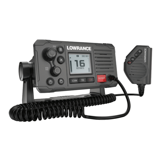
- Page 1 Link™-6S Fixed Mount VHF User Guide ENGLISH lowrance.com...
- Page 2 Preface Disclaimer As Navico is continuously improving this product, we retain the right to make changes to the product at any time which may not be reflected in this version of the manual. Please contact your nearest distributor if you require any further assistance.
- Page 3 European Union This Link-6S complies with CE under RED Directive 2014/53/EU. The relevant Declaration of conformity is available in the product’s section at the following website: www.navico.com Countries of intended use in the EU AT - Austria HU - Hungary...
- Page 4 United Kingdom Hereby, Navico declares that the radio equipment type Link-6S is in compliance with Radio Equipment Regulations 2017. The full text of the UK declaration of conformity is available at the following internet address: www.lowrance.com. United States Part 15 of the FCC Rules. Operation is subject to the following two...
- Page 5 Canada This device complies with Innovation, Science and Economic Development Canada’s (ISED) licence-exempt RSSs. Operation is subject to the following two conditions: This device may not cause interference; and This device must accept any interference, including interference that may cause undesired operation of the device. Le présent appareil est conforme aux CNR d’Innovation, Sciences et Développement économique Canada (ISDE) applicables aux appareils radio exempts de licence.
- Page 6 2017 and Radiocommunications (VHF Radiotelephone Equipment – Maritime Mobile Service) Standard 2014. Trademarks Link™ is a common law trademark of Navico Holding AS. Lowrance® is a registered trademark of Navico Holding AS. NMEA®, NMEA 0183® and NMEA 2000® are registered trademarks of the National Marine Electronics Association.
- Page 7 same range restrictions that apply to regular VHF transmissions. The vessel sending a distress can only rely upon DSC if within range of a GMDSS Coast Radio Station. Typical VHF range may be about 20NM, though this varies greatly depending upon installation, antenna type, meteorological conditions, etc.
-
Page 8: Table Of Contents
Contents General Information How to display and navigate menus Key functions The radio menus Scan Watch Display Radio setup DSC setup Alarms Reset DSC call menu DSC calls Track buddy Contacts My channels Shortcuts Installation Checklist Installation options Selecting a suitable mounting location First startup configuration Specifications Channel charts... -
Page 9: General Information
General Information Your Link-6S provides the following useful features: • Prominent channel display • Built-in GPS receiver and antenna • With external GPS antenna connection • Adjustable contrast settings for the LCD • Adjustable keypad backlighting for easy night-time use •... -
Page 10: How To Display And Navigate Menus
How to display and navigate menus The majority of the buttons, and both of the rotary knobs, can open menus with multiple options. The channel knob is used to scroll through the options. The currently selected option is indicated by a black highlight bar, and the text is inverted to white. - Page 11 During normal operation, the following icons may be displayed on the screen depending on setup: Symbol Meaning Transmitting Transmition power Weather channel stored by user (EU & INT only) Weather alert enabled (USA/CAN only) Receiver Busy with incoming signal Missed DSC call Duplex channel selected (off when Simplex) Local mode enabled (used when in areas of high radio traffic, ie inner harbour)
- Page 12 A typical display: Channel is set to high power transmit Missed call in the DSC call log Channel is busy Volume is under active control Current channel saved in ‘My Channels’ Track your buddy is enabled Current channel will be skipped during a scan Volume level indicator Time (derived from GPS) - UTC offset is applied Latitude/Longitude...
-
Page 13: Key Functions
Key functions The following describes the direct functions of the keys/knobs. Where necessary, additional detail on any menus accessed by keys is covered in following chapters. 12 13 7 8 9 Channel knob / PUSH TO SELECT Turn knob for channel selection, menu scrolling, alphanumeric entry, and fine adjustment of backlight level (dependent on active menu). - Page 14 adjustments. Long press to turn radio on or off. Weather Channel Short press (US/CAN models): press to hear the most recently selected NOAA/Canadian weather station. For all other models, changes channel to user programmed choice. Long press (non US/CAN models): to store current channel as the weather channel.
- Page 15 16 / 9 (radio and handset) Short press to change to priority channel. Press again to return to original channel. For US models: Long press to make Channel 09 the priority channel. The default Priority Channel is CH16. DISTRESS Short press to start a distress call, where the nature of distress can be selected from a list.
-
Page 16: The Radio Menus
The radio menus A long press of the MENU button opens MENU SELECT page. The following shows the menu structure (top and 2nd level only): ALL SCAN ALL CHANNELS + 16 SCAN MY CHANNELS MY CHANNELS + 16 EDIT MY CHANNELS (choose channels) DUAL WATCH WATCH TRI WATCH... -
Page 17: Watch
All channels + 16 Scans all channels cyclically, but checks the priority channel after every channel step My channels Scan all channels selected in EDIT MY CHANNELS My channels + 16 Scans all channels selected in EDIT MY CHANNELS, while also checking the priority channel after every channel step. -
Page 18: Display
Set Watch Channel Allows a watch channel to be selected from all available channels. Selected channel is used by TRI WATCH mode. ¼ Note: If the radio is configured for USA market, two priority channels are watched: Channel 9 and Channel 16. Display This menu allows the user to partially customize the screen information displayed, and adjust the screen for best visibility to suit... -
Page 19: Radio Setup
Radio setup The Radio setup menu covers settings that are typically configured at installation, and seldom need changing. Local/Dist Use LOCAL/DIST to improve the sensitivity of the receiver either locally (LOCAL) or over distances (DIST). LOCAL is not recommended for use in open sea conditions. It is designed for use in areas of high radio noise;... - Page 20 A true north heading is corrected for magnetic declination. A magnetic north heading source must also output magnetic variation data if the heading is to be displayed as a true north value. Int speaker Select to switch the radio’s internal speaker ON or OFF. Ext speaker Select to switch the radio’s external speaker ON or OFF.
- Page 21 GPS SIM Select to toggle ON or OFF. Whenever the GPS Simulator is turned ON, simulated Speed Over Ground (SOG), Course Over Ground (COG), and LL position appear on the screen. This is for the purpose of demonstration only. The SIM icon is displayed to warn the user it is in this mode.
-
Page 22: Dsc Setup
DSC setup DSC Function It’s recommended DSC functionality is always enabled, unless operating the vessel in an ATIS region. An MMSI number must be entered in radio before the DSC function can be enabled. User MMSI Enter an MMSI number to access the radio’s DSC functionality. This unique identifier must be supplied a local radio spectrum authority. - Page 23 MANUAL Operator must manually choose to send acknowledgement, as well as change to requested channel. EU model default. ¼ Note: This does not apply for calls types other than ‘Individual’. Position request acknowledge (“POS ACK”) The radio can be configured to automatically acknowledge an incoming position request, require manual intervention to acknowledge, or simply ignore them: AUTO...
-
Page 24: Alarms
Receive distress while off Enabling this feature will allow the radio to raise an alert for DSC distress calls, even when the DSC feature is turned off. This will work regardless of whether or not an MMSI number has been entered. DSC timeout An inactivity timeout can be set up to return the radio to normal operational mode when no activity is seen from the radio operator... -
Page 25: Reset
WX alert function Turns ON or OFF the radios response to weather alerts. This includes; automatic switching to the last used weather channel, audible alarm, screen message, and flashing backlight. Alert volume Select between HIGH, LOW, and OFF. Screen flash Select between ON and OFF. -
Page 26: Dsc Call Menu
DSC call menu DSC (Digital Selective Calling) is a semi-automated method of establishing VHF, MF, and HF radio calls. One big advantage that DSC enabled radios offer is that they can receive calls from another DSC radio without being on the same channel as the calling radio. The calling radio will provide details on what channel to switch to so that voice communication can be established. - Page 27 The Distress Call is automatically re-sent every 3.5 to 4.5 minutes until a distress acknowledgement is received. Alternatively the operator can select: RESEND (under OPTION - access by pressing the Menu/DSC button) used to immediately resend the Distress Call PAUSE (under OPTION - access by pressing the Menu/DSC button) used to pause the automatic Distress Call resend timer CANCEL (press ‘X’...
-
Page 28: Track Buddy
All ships Used to place a call to ALL DSC equiped vessels in range, much like a distress call. The nature of the call must be selected, and can be either SAFETY or URGENCY. When the SEND TO page is displayed, turn the channel knob to select the channel to use for voice communication. -
Page 29: Contacts
Select buddy Shows any existing ‘buddies’ already selected, and the option to add more. Selecting a ‘buddy’ already in the buddy list will remove them. Choose ADD/UPDATE BUDDY to view the full contacts list, and choose who to add for tracking. Start tracking / Stop tracking Selecting START TRACKING option initiates tracking of buddies in the Track buddy list that have been set to tracking ON. - Page 30 View/Add Contact Use this to store the names and associated MMSI’s of up to 50 vessels to be called regularly using DSC. Contacts are stored by name, in alphabetical order. Select ADD NEW to create a new contact. Selecting an existing name in the Contacts list gives the options to place a DSC call, make a position request, edit the contact, or delete the contact.
-
Page 31: My Channels
My channels The MY CHANNELS page is accessed by a long press of the channel knob. This page provides a shortcut to frequently accessed channels. The first time this page is opened, the entire channel list is shown so that the desired shortcut channels can be selected. Subsequent opening of this page will show a list of only the selected channels. -
Page 32: Shortcuts
Shortcuts The Shortcuts page is accessed by a long press of the VOL/SQL knob. This page is provided as a shortcut to frequently accessed settings. The shortcut options available on this page are subject to selections made in ADD/EDIT SHORTCUTS. Add/Edit shortcuts Choose from the list of options which menu options should be added as shourtcuts;... -
Page 33: Installation
Installation This Lowrance DSC VHF radio is designed to generate a digital maritime distress call to facilitate search and rescue. To be effective as a safety device, this radio must be used only within the geographic range of a shore-based VHF marine Channel 70 distress and safety watch system. -
Page 34: Installation Options
Installation options There are two mounting options for the radio: • Bracket mount: Using the supplied gimballing bracket the radio can be mounted to either sit on top of, or hang underneath any flat horizontal surface. The radio can be removed for storage and the viewing angle can be adjusted. - Page 35 Built-in GPS considerations The built-in GPS antenna is mounted in the front face of this radio above the speaker grill. If you intend to use the built-in GPS Antenna in this radio, you must ensure a suitable mounting location that allows optimal GPS performance.
- Page 36 Flush installation Tape the installation template onto the chosen mounting location. Cut out the area marked by the solid dark line (the dashed line indicates the total area that will be covered by the radio fascia after installation). Use a 2.5 mm (3/32” ) drill bit to drill the 4 pilot holes. Remove the installation template.
- Page 37 Install the external GPS-500 Antenna (optional) It is not recommended that the GPS antenna is mounted up a mast where the motion of the vessel will cause the antenna to swing and potentially reduce the accuracy of the GPS position. Also, do not mount the antenna in the direct path of a radar transmitter.
- Page 38 • Run the GPS cable to the transceiver: • Route the cable to your VHF transceiver unit, adding any necessary extension cables. • Connect the cable from the GPS antenna to the GPS connector (SMA) on the VHF transceiver as shown below. Connect the radio wiring All wiring on the radio should be done with the vessel power supply turned off.
-
Page 39: First Startup Configuration
5. NMEA 0183® TX_A (white): connect to RX_A of chart plotter 6. NMEA 0183® TX_B (brown): connect to RX_B of chart plotter Antenna: connect to a marine VHF antenna using 50 ohm cable fitted with a PL-259 connector GND: optional ground connection. May help with induced noise issues Optional External GPS Antenna connection (SMA). - Page 40 number to confirm correct entry. Enter vessel call sign if known, or skip to next step. Select a GPS source Set the time offset for your region. Choose whether to display time in 12 or 24 hour. MMSI and ATIS ID The MMSI is a unique 9 digit number and the ATIS ID is a 10 digit number.
- Page 41 • An ATIS ID is only required in certain EU countries when navigating some inland waterways. It is usually a different number to your MMSI. • If you need to have the MMSI in the radio changed, the radio must be taken back to your Lowrance dealer.
-
Page 42: Specifications
Specifications GENERAL Power supply: 12 V DC battery system Nominal operating voltage: + 13.6 V DC Low battery alert: 10.5 V DC +/- 0.5 V Over voltage protection: > 15.8 V +/- 0.5 V Current drain (Transmit): ≤ 6 A @ 25 W / 1.5 A @ 1W (12 V DC) Current drain (Receive): Less than 450 mA in standby Replacement Fuse:... - Page 43 NMEA 2000® port: External speaker: FEATURES Flush mount kit Local/Distant control: Position polling: Group call: Call logs: Yes - 20 individual and 10 distress Channel naming: Tri watch: Favourite channel scan: All scan: User programmable MMSI: MMSI and NAME directory: Yes - 20 numbers &...
- Page 44 Residual noise level: more than -40 db unsquelched Audio output power: 2 W (with 8 ohm at 10% distortion) 4 W (with 4 ohm external speaker BUILT-IN GPS RECEIVER Receiving frequency: 1575.42 MHz Tracking code: C/A code Number of channels: 72 channels Horizontal accuracy: <10 m...
-
Page 45: Channel Charts
Channel charts The following channel charts are provided for reference only and may not be correct for all regions. It is the operators’ responsibility to ensure correct channels and frequencies are used for local regulations. EU and International channel chart With reference to Appendix 18 (Rev.WRC-15) (See article 52). - Page 46 Transmitting frequencies Port operations and ship Public (MHz) movement Channel Inter- Notes corres- designator ship From ship From coast Single pondence stations stations frequency frequency 156.025 160.625 156.050 160.650 156.075 160.675 156.100 160.700 156.125 160.725 156.150 160.750 156.175 160.775 156.200 160.800 156.225 160.825...
- Page 47 156.950 161.550 1019 156.950 156.950 2019 161.550 156.975 161.575 1079 156.975 156.975 2079 161.575 157.000 161.600 1020 157.000 157.000 2020 161.600 y), wa) 157.025 161.625 y), wa) 157.050 161.650 y), wa) 157.075 161.675 y), wa) 157.100 161.700 x), y), wa) 157.125 161.725 x), y), wa)
- Page 48 86 w), ww), x) 157.325 161.925 1086 w), ww), x) 157.325 2086 w), ww), x) 161.925 z), zx) 157.350 161.950 1027 z), zz) 157.350 157.350 ASM 1 161.950 161.950 z), zz) 157.375 157.375 z), zx) 157.400 162.000 1028 z), zz) 157.400 157.400 ASM2...
- Page 49 • implementation of 12.5 kHz channel interleaving and consequential national requirements shall be subject to coordination with affected administrations. (WRC-12) Specific notes f) The frequencies 156.300 MHz (channel 06), 156.525 MHz (channel 70), 156.800 MHz (channel 16), 161.975 MHz (AIS 1) and 162.025 MHz (AIS 2) may also be used by aircraft stations for the purpose of search and rescue operations and other safety-related communication.
- Page 50 stations for transmission. All precautions should be taken to avoid harmful interference to channels AIS 1, AIS 2, 2027* and 2028*. (WRC- * From 1 January 2019, channel 2027 will be designated ASM 1 and channel 2028 will be designated ASM 2. mm) Transmission on these channels is limited to coast stations.
- Page 51 From 1 January 2017, the frequency bands 157.200-157.325 MHz and 161.800-161.925 MHz (corresponding to channels: 24, 84, 25, 85, 26 and 86) are identified for the utilization of the VHF Data Exchange System (VDES) described in the most recent version of Recommendation ITU-R M.2092.
- Page 52 85) may be used for digitally modulated emissions, such as those described in the most recent version of Recommendation ITU-R M.2092, subject to coordination with affected administrations. (WRC-15) x) From 1 January 2017, in Angola, Botswana, Lesotho, Madagascar, Malawi, Mauritius, Mozambique, Namibia, Democratic Republic of the Congo, Seychelles, South Africa, Swaziland, Tanzania, Zambia and Zimbabwe, the frequency bands 157.125-157.325 and 161.725-161.925 MHz (corresponding to channels: 82, 23, 83, 24, 84, 25, 85, 26 and 86) are...
-
Page 53: Usa Channel Chart
USA channel chart Transmitting frequencies (MHz) Channel S/D/R Channel name Restrictions From ship From coast designator stations stations 156.300 156.300 SAFETY 156.400 156.400 COMMERCIAL 156.450 156.450 CALLING 156.500 156.500 COMMERCIAL 156.550 156.550 156.600 156.600 PORT OPS/VTS 156.650 156.650 BRIDGE COM 156.700 156.700 PORT OPS/VTS... - Page 54 1007 (was 07A) 156.350 156.350 COMMERCIAL 1018 (was 18A) 156.900 156.900 COMMERCIAL 1019 (was 19A) 156.950 156.950 COMMERCIAL 1020 (was 20A) 157.000 157.000 PORT OPS 1021 (was 21A) 157.050 157.050 US COAST GRD 1022 (was 22A) 157.100 157.100 US COAST GRD 1023 (was 23A) 157.150 157.150...
-
Page 55: Canada Channel Chart
Canada channel chart Transmitting frequencies (MHz) Channel S/D/R Channel name Restrictions From ship From coast designator stations stations 156.050 160.650 TELEPHONE 156.100 160.700 TELEPHONE 156.150 160.750 TELEPHONE 156.200 160.800 CANADIAN CG 156.250 160.850 TELEPHONE 156.300 156.300 SAFETY 156.350 160.950 TELEPHONE 156.400 156.400 COMMERCIAL... - Page 56 156.725 156.725 156.775 156.775 PORT OPS 156.825 156.825 PORT OPS 156.875 156.875 PORT OPS 156.925 161.525 TELEPHONE 156.975 161.575 TELEPHONE 157.025 161.625 TELEPHONE 157.075 161.675 TELEPHONE 157.125 161.725 CANADIAN CG 157.175 161.775 CANADIAN CG 157.225 161.825 TELEPHONE 157.275 161.875 TELEPHONE 157.325 161.925 TELEPHONE...
- Page 57 2079 161.575 PORT OPS RX ONLY 2086 161.925 PORT OPS RX ONLY Canada weather channels Transmitting frequencies (MHz) Channel S/D/R Channel name Restrictions From ship From coast designator stations stations 162.550 CANADA WX Rx only 162.400 CANADA WX Rx only 162.475 CANADA WX Rx only...
-
Page 58: Dimensional Drawings
Dimensional drawings 60 mm (2.36”) 166.7 mm (6.56”) 161.4 mm (6.35”) 58 | Dimensional drawings | Link-6S User Guide...
Need help?
Do you have a question about the Lowrance Link-6S and is the answer not in the manual?
Questions and answers