Table of Contents
Advertisement
Quick Links
LOWRANCE
LVR-880US & LVR-880EU
VHF Radio
Operation Instructions
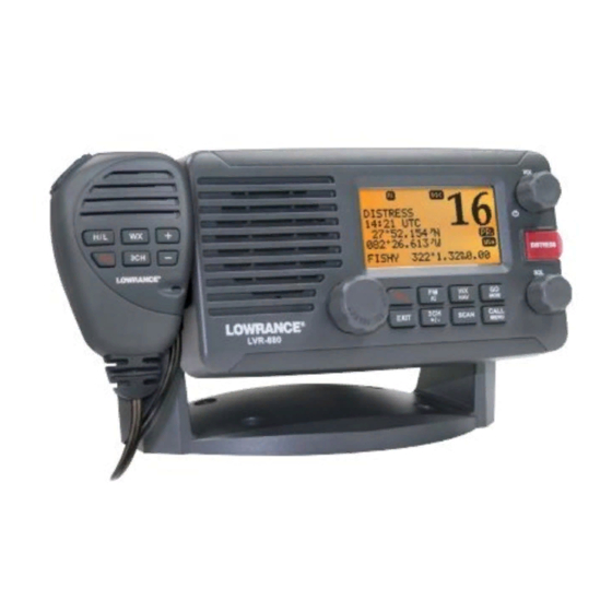
Pic of LVR-880US
LVR-880US
Pic of LVR-880EU
LVR-880EU
FCC RF Exposure
The antenna(s) used for this transmitter must not be co-located or operating in conjunction with any
other antenna or transmitter. This device is approved with emissions having a source-based time-averaging
duty factor not exceeding 50%.Maintain a minimum of 89 cm (35 inches) distance between the antenna
and any person.Failure to observe these restrictions will result in exceeding the FCC RF exposure
limits.
1
Advertisement
Table of Contents

Related Manuals for Navico Lowrance LVR-880US


Summary of Contents for Navico Lowrance LVR-880US
-
Page 1: Lowrance
LOWRANCE LVR-880US & LVR-880EU VHF Radio Operation Instructions Pic of LVR-880US LVR-880US Pic of LVR-880EU LVR-880EU FCC RF Exposure The antenna(s) used for this transmitter must not be co-located or operating in conjunction with any other antenna or transmitter. This device is approved with emissions having a source-based time-averaging duty factor not exceeding 50%.Maintain a minimum of 89 cm (35 inches) distance between the antenna and any person.Failure to observe these restrictions will result in exceeding the FCC RF exposure limits. - Page 2 Copyright © 2008 Navico All rights reserved. Lowrance™ is a registered trademark of Navico. Insert standard copyright protection, disclaimer, website and address information. Insert standard safety information and icons.
-
Page 3: Table Of Contents
CONTENTS LOWRANCE ..........................1 LVR-880US & LVR-880EU....................1 VHF Radio ..........................1 Operation Instructions......................1 General Information ....................6 Features ..............................6 LCD Symbols and Meanings.......................6 Beep tones & call alerts ........................8 How to put the radio into MENU mode....................8 How to Display and Navigate Menus ....................8 How to Enter Alphanumeric Data ......................8 The Radio Keys ......................9 Φ... - Page 4 Set the Contrast Level (CONTRAST) ....................20 GPS Data and Time (GPS/DATA) ....................21 3.6.1 Manually Enter Position and UTC Time (MANUAL)..........21 3.6.2 Local Time (TIME OFFSET)................21 3.6.3 Time Format Options (TIME FORMAT)............. 22 3.6.4 Time Display Options (TIME DISPLY)............... 22 3.6.5 Position Display Options (LL DISPLY) ..............
- Page 5 6.16 Receiving an All Ships Call (ALL SHIPS)..................42 6.17 Receiving an Individual Call (INDIV) ....................42 6.18 Receiving a Group Call (GROUP).....................43 6.19 Receiving a Geographic Area Call (GEOGRAPH) ................43 6.20 Receiving a Polled Position Call (POSITION) ...................43 DISTRESS Calls....................45 Sending a Distress Call........................45 Receiving a Distress Call (DISTRESS!)....................45 Distress Acknowledgement (DISTRESS ACK) or Relay (DISTRESS REL) ........46 Appendix A - Technical Specifications ................47...
-
Page 6: General Information
General Information 1.1 Features Congratulations on your purchase of a Lowrance LVR-880US or LVR-880EU marine band VHF radio. Both models provide you with the following useful features: • Prominent channel display • Adjustable contrast settings for the LCD • Adjustable keypad backlighting for easy night-time use •... - Page 7 Symbol Meaning Transmitting. Tx BUSY Receiver busy with an incoming signal. SCAN Scanning for the broadcasting channel. Press PTT to stop scanning. When the broadcasting channel is found, scanning stops at that channel. DSC capability is available. Envelope symbol Incoming DSC call OR blinks to notify you of any unread call log messages. Distress Channel name tag.
-
Page 8: Beep Tones & Call Alerts
• your latitude (40°30.5223N) and longitude (120°23.1231E) and UTC time in 12 hour format (12:15pm). • the name of the destination waypoint (FISHY), its bearing (138°), your distance in nautical miles, mile, or kilometers (depending on your choice of units), and any cross track error (XTE) are shown. -
Page 9: The Radio Keys
The Radio Keys All possible keys and their functions are listed here. Note that some of the keys may not available, depending on your Lowrance VHF radio model. 2.1 Φ VOL Volume and Power. Turn clockwise to power on. After displaying the startup LCD briefly, the radio goes to operational mode in CH16, Hi power transmission, and shows your current position and time if GPS data is available. -
Page 10: Fm (Fm Stereo Radio)
2.7 16 LVR-880EU only. Priority channel. Also on the microphone. Press to cancel all other modes and to tune into the priority channel, Channel 16, on high power. Press again to return to your original channel. 2.8 FM (FM Stereo Radio) Note: You need to select your FM region. -
Page 11: Nav (Show Waypoint)
• AGROUND • SIREN 3. Scroll through the menu to select a fog horn, then press ENT to start the fog horn sounding. The fog horn will sound automatically until you press EXIT to cancel it. When the fog horn is not sounding, it is in LISTEN mode. -
Page 12: Mob (Temporary Waypoint)
2.14 MOB (Temporary Waypoint) To mark your current position as a temporary waypoint, hold down MOB and release the key before the 3 second countdown ends. You will see the following sequence of LCDs: Hold 3 Sec Hold 2 Sec Hold 1 Sec For MOB For MOB... -
Page 13: Scan (Dual Watch Mode)
When a signal is received, scanning stops at that channel and BUSY appears on the LCD. If the signal ceases for more than 5 seconds, the scan restarts. Press SCAN or PTT to stop at the current channel. If you are in NAVIGATION mode or FM RADIO mode and want to scan the DSC channels while staying in that mode, just hold down SCAN. -
Page 14: Call Menu
hazard alert on the selected weather channel. 2.22 CALL MENU Make DSC calls. Press to enter the DSC CALL menu and make DSC calls. Enter MENU mode. Hold down for about 3 seconds to show the radio MENU so that you can customize your radio, enter categories, and enter alphanumeric data. -
Page 15: Radio Menu Select Options
Radio MENU SELECT Options Hold down CALL MENU for about 3 seconds to access any of the following radio MENU SELECT options. Menu options shown inside the gray boxes are explained in this chapter. WAYPOINT Section 3.1 BACKLIGHT Section 3.2 BUDDY LIST Section 3.3 LOCAL/DIST... -
Page 16: Manage Your Waypoints List (Waypoint)
3.1 Manage your Waypoints List (WAYPOINT) You can store a maximum of 200 waypoints with their LL positions. When your waypoint list is full, you cannot make a new entry until you have deleted an existing entry. Each waypoint name can have a maximum of 6 alphanumeric characters. Waypoints are stored in order of entry, with the most recent entry shown first. -
Page 17: Go To A New Waypoint
7. Press ENT to store the changes. The waypoint list is displayed again. If more changes are required, repeat steps 2 through 6. Otherwise, press EXIT to cancel any edits. 3.1.3 Go to a New Waypoint MENU SELECT WAYPOINT WP LIST R01W01 >WAYPOINT >WP LIST... -
Page 18: Send Waypoint Data To A Chartplotter
TEMP WP FULL DELETE TMP1? >YES 3.1.6 Send Waypoint Data to a Chartplotter You can send waypoint data over NMEA2000 to a compatible chartplotter. MENU SELECT WAYPOINT TEMP TEMP2 >WAYPOINT WP LIST TEMP1 >GO BACKLIGHT NEAREST WP >TEMP2 WP EDIT BUDDY LIST >TEMP 5. -
Page 19: Maintain Your Buddy List (Buddy List)
1. Select BACKLIGHT. 2. Select a comfortable backlight level using the Channel Select knob or + or – to change the setting. Note: If you set the backlight level to zero, the base station backlight and the microphone backlight will turn OFF. Otherwise, they will both be ON. 3. -
Page 20: Local Or Distance Sensitivity (Local/Dist)
3. Select EDIT. The cursor is at the first character of the name. Note: To delete the buddy, select DELETE then YES. The buddy is deleted immediately and the buddy list is displayed again. 4. Edit the buddy name OR to edit only the MMSI, press ENT repeatedly until the cursor moves to the MMSI line. -
Page 21: Gps Data And Time (Gps/Data)
2. Select a comfortable contrast level using the Channel Select knob or + or – on the microphone to change the setting. 3. Press ENT to enable the setting and return to the menu. 3.6 GPS Data and Time (GPS/DATA) If the boat has an operational GPS navigation receiver, the VHF radio automatically detects and updates the vessel position and the local time. -
Page 22: Time Format Options (Time Format)
1. Work out the time difference between UTC and your local time. 2. Select GPS/DATA then SETTING. 3. Select TIME OFFSET to enter the difference between UTC and local time. Use the Channel Select knob OR + or – to change the time. Half hour increments can be used with a maximum offset of ±13 hours. -
Page 23: Position Display Options (Ll Disply)
1. Select GPS/DATA then SETTING. 2. Select TIME DISPLY. 3. Select ON (on) or OFF (off) as desired. In this example, OFF has been selected and the LCD no longer shows the time. Note: If the time display is set ON, course and speed data are NOT displayed on the LCD, irrespective of the COG/SOG setting. -
Page 24: Gps Simulator (Gps Sim)
3.7 GPS Simulator (GPS SIM) The GPS simulator is set to OFF whenever the radio is turned ON or whenever real GPS data is available through the COM port. (The GPS simulator will not operate if a GPS signal is received.) However, if you want to test it, turn it ON. -
Page 25: Radio Setup Menu (Radio Setup)
Radio Setup Menu (RADIO SETUP) Hold down CALL MENU for about 3 seconds to access the following RADIO SETUP options. Menu options shown inside the gray box are explained in this chapter. WAYPOINT Section 3.1 BACKLIGHT Section 3.2 BUDDY LIST Section 3.3 LOCAL/DIST Section 3.4... -
Page 26: Channel (Uic)
4.1 Channel (UIC) LVR-880US only. Toggle between USA, International, or Canadian channel banks. The selected channel bank is displayed on the LCD along with the last used channel. All the channel charts are shown in Appendix RADIO SETUP >UIC >USA CH NAME INT’L RING VOLUME... -
Page 27: Key Beep Volume (Key Beep)
1. Select RADIO SETUP then RING VOLUME. 2. Select HIGH (loud) or LOW (soft) then press ENT. 4.4 Key Beep Volume (KEY BEEP) You can change the key beep volume or turn the key beeps off completely. RADIO SETUP KEY BEEP CH NAME HIGH RING VOLUME... -
Page 28: Weather Alerts (Wx Alert)
1. Select RADIO SETUP then WATCH MODE. 2. Select the desired setting then press ENT. 4.8 Weather Alerts (WX ALERT) LVR-880US only. Use WX ALERT to set your preferences for weather alert information. The NOAA provides several weather forecast channels on USA and Canadian channel banks. If severe weather such as storms or hurricanes are forecast, the NOAA broadcasts a weather alert on 1050 Hz. -
Page 29: Receiving A Same Alert
4.8.3 Receiving a SAME ALERT LVR-880US only. If SAME ALERT alert is ON and an NWR or EAS alert for your geographic area is broadcast by the NOAA NWR transmitters, the alert is picked up automatically and the alarm sounds. Press any key to cancel the alarm. -
Page 30: Select The Gps Source (Gps Source)
The COM PORT must be configured correctly before use. The radio can be added to a group of instruments using NMEA protocol. RADIO SETUP NMEA UNITS CHECK SUM INT SPEAKER >ON >COM PORT 1. Select RADIO SETUP then COM PORT. 2. -
Page 31: Dsc Setup Menu (Dsc Setup)
DSC Setup Menu (DSC SETUP) Warning. A valid USER MMSI must be entered into the radio before these DSC functions can be used. See Section 5.1 for instructions on entering your USER MMSI. Hold down CALL MENU for about 3 seconds to access any of the following DSC SETUP options. Menu options shown inside the gray box are explained in this chapter. -
Page 32: Enter Or Check Your User Mmsi (User Mmsi)
5.1 Enter or Check Your USER MMSI (USER MMSI) This is a ONCE-ONLY operation. You must enter your user MMSI before you can access the DSC functions. You can display and read your user MMSI at any time, but you get only one opportunity to enter your user MMSI. -
Page 33: Edit Or Delete A Group Name Or Group Mmsi (Group Setup)
4. Enter the group MMSI. (Note that the first number is always a 0.) Press ENT. 5. The group name and group MMSI are shown in a confirmation screen. Press ENT to store the details and return to the GROUP SETUP screen. 5.2.2 Edit or Delete a Group Name or Group MMSI (GROUP SETUP) You can edit a group name or group MMSI at any time. -
Page 34: Enable Atis Functionality (Atis Select)
If you have already entered your ATIS MMSI, it is shown on the LCD. 2. If this is the first time that you are entering your ATIS MMSI, a dashed line appears. Enter your ATIS MMSI along the dashed line. The first number is always 9. Press ENT to confirm each correct entry and to move to the next digit. - Page 35 DSC SETUP LL REPLY ATIS SELECT >MANUAL DSC SELECT AUTO >LL REPLY 1. Select DSC SETUP then LL REPLY. 2. Select your response and press ENT to confirm and return to the menu.
-
Page 36: Sending And Receiving Dsc Calls
Sending and Receiving DSC Calls Warning. A valid USER MMSI must be entered into this radio before these DSC functions can be used. See section 5.1. 6.1 What is DSC? DSC (Digital Selective Calling) is a semi-automated method of establishing VHF, MF, and HF radio calls. -
Page 37: Send An Individual Call (Individual)
1. Select DSC CALL then INDIVIDUAL. 2. Select the priority level. 3. Select the buddy you want to call from your buddy list. 4. Press ENT to SEND the call. Channel 70 is selected automatically and the Tx symbol is shown on the LCD while the call is being sent. -
Page 38: Reply To The Last Call (Last Call)
2. The caller should respond to your acknowledgement by making voice contact on the designated channel. If not, you can press PTT to initiate voice contact instead. 6.6 Reply to the Last Call (LAST CALL) This facility is useful and used frequently. DSC CALL SEA ROSE SEA ROSE... -
Page 39: Send Using The Call Log (Call Log)
• ROUTINE - To send a routine call to all other vessels in range 4. Then set the channel and continue as explained in Section 6.4. 6.9 Send Using the Call Log (CALL LOG) The Call Log contains the contact details for the 20 most recent incoming calls, so that you can call any of them again quickly. -
Page 40: Send An Individual Distress Relay Using The Distress Log (Dist Log)
6.11 Send an Individual Distress Relay Using the Distress Log (DIST LOG) You can make a distress relay to an individual in the log. DSC CALL 05 SUNSHINE DISTRESS ALL SHIPS DISTRESS 10:03 UTC CALL LOG FLOODING 82º50.1245 N >DIST LOG ALL RELAY 027º45.4561 W 05 SUNSHINE... -
Page 41: Track A Buddy (Track Buddy)
STARFISH LL REQUEST WAITING ACK 1. Select DSC CALL then LL REQUEST. 2. Select the buddy whose LL position you want to request and press ENT. 3. Press ENT again to SEND the request. The working channel is displayed while the radio waits for an acknowledgement from your buddy. If there is no reply after 30 seconds the radio asks if you want to retry. -
Page 42: Add Or Delete A Buddy On Your Track List (Tracklist)
3. Select the buddy whose status you want to change, then select the new status and press ENT to confirm. 6.14.3 Add or Delete a Buddy on Your Track List (TRACKLIST) DSC CALL TRACK BUDDY TRACKLIST ADD NEW DISTRESS LOG START TRACK >ADD NEW >MERMAID IV... -
Page 43: Receiving A Group Call (Group)
RCV: INDIV 12 CHANNEL 123456789 REQUEST ROUTINE ENT ACK EXIT ESC 1. When you receive notification of an INDIV call, press any key to cancel the alert. The radio manually selects the channel designated in the incoming call by pressing ENT key. INDIV calls are almost always routine priority. - Page 44 EXIT ESC 127°45.1425W When you receive GPS position data from a buddy in response to your LL request (see Section 6.13) you are recommended to make a written note of the position, especially is it is a good fishing position. If enhanced LL position information is available from your buddy, this is shown on the screen until the screen display changes.
-
Page 45: Distress Calls
DISTRESS Calls Warning. A valid USER MMSI must be entered into this radio before these DSC functions can be used. See section 5.1. 7.1 Sending a Distress Call DISTRES CALL DISTRES CALL DISTRES CALL >UNDEFINED >UNDEFINED SENT! WAIT.. FIRE HOLD DISTRES PRESS EXIT FLOODING 3 SECONDS.. -
Page 46: Distress Acknowledgement (Distress Ack) Or Relay (Distress Rel)
the location (if specified). If the location and time are not specified, these are replaced with sequences of 9s and 8s respectively. The radio is capable of receiving enhanced LL position data if the vessel transmitting the distress call is sending this. This provides the position of the distressed vessel to within 20 m (60 ft). 7.3 Distress Acknowledgement (DISTRESS ACK) or Relay (DISTRESS REL) An alert sounds when a distress relay (DISTRESS REL) is received from another vessel OR when a distress acknowledgement (DISTRESS ACK) is received from the Coast Guard. -
Page 47: Appendix A - Technical Specifications
Appendix A - Technical Specifications LOWRANCE LVR-880US & LVR-880EU IDT TO SUPPLY LATEST TECH SPEC GENERAL Frequency Range: Transmit 156.025 to 157.425 MHz Receive 156.050 to 162.425 MHz Oscillate Mode Modulation FM (16KOG3E) DSC(16K0G2B) Channel Spacing 25 KHz Frequency Stability ±10 PPM... -
Page 48: Fm Stereo Receiver
Spurious/Harmonic Emissions: HI/LO 80/60 dB Current Drain at 13.6V DC : Hi Power ≤6 A Lo Power ≤1.5 A Specifi cations are subject to change without notice. FM STEREO RECEIVER INFORMATION REQUIRED FROM IDT HAILER Audio Power Out: 22W @ 4 OHMS... -
Page 49: Appendix B - Troubleshooting
Appendix B - Troubleshooting 1. The transceiver will not power up. A fuse may have blown OR there is no voltage getting to the transceiver. a) Check the power cable for cuts, breaks, or squashed sections. b) After checking the wiring, replace the 7 Amp fuse. c) Check the battery voltage. -
Page 50: Appendix C - Vhf Marine Channel Charts
Appendix C - VHF Marine Channel Charts International Channel Chart Insert chart... -
Page 51: Usa Channel Chart
USA Channel Chart Insert chart... -
Page 52: Canada Channel Chart
CANADA Channel Chart Insert chart... -
Page 53: Canada Channel Chart
CANADA Channel Chart Insert chart... -
Page 54: Weather Channels
Weather Channels Insert chart... -
Page 55: Eas (Emergency Alert Systems) Alerts
EAS (Emergency Alert Systems) Alerts National Codes Event Codes Message Nature of Activation Emergency Action Notification (National only) WARNING ADVISORY National Information Center ADVISORY National Periodic Test TEST Required Monthly Test TEST Required Weekly Test TEST State and Local Codes Event Codes Message Nature of Activation... - Page 56 911 Telephone Outage Emergency WARNING Nuclear Power Plant Warning WARNING Radiological Hazard Warning WARNING Severe Thunderstorm Warning WARNING Severe Thunderstorm Watch WATCH Severe Weather Statement ADVISORY Shelter in Place Warning WARNING Special Marine Warning WARNING Special Weather Statement ADVISORY Tornado Warning WARNING Tornado Watch WATCH...
-
Page 57: Appendix D - Eu Inland Waterway Channels
Appendix D - EU Inland Waterway Channels Insert chart... -
Page 58: Appendix E - Mmsi & License Information
Appendix E - MMSI & License Information You must obtain a user MMSI (Marine Mobile Service Identity) and enter it into your radio in order to use the DSC functions. Contact the appropriate authorities in your country. If you are unsure who to contact, consult your Lowrance dealer. -
Page 59: Warranty
Warranty Insert Warranty Information... -
Page 60: How To Obtain Service
How to Obtain Service Insert How to Obtain Service details In the USA In Canada Outside Canada and the USA Accessory Ordering Information for all countries Shipping Information BACK COVER ARTWORK PART NUMBER...
Need help?
Do you have a question about the Lowrance LVR-880US and is the answer not in the manual?
Questions and answers