Table of Contents
Advertisement
Quick Links
(460V/575V Three Phase, via stepdown transformer accessories)
U L
C
NOT FOR RESIDENTIAL USE
• Please read this manual and the enclosed safety materials completely, prior to installation
and use!
LISTED
• This product is to be installed and serviced by a trained door systems technician ONLY.
• These operators are compatible with myQ
accessories.
• These operators are Wi-Fi compatible.
U L
C
US
LISTED
U L
C
US
U L
C
US
LISTED
LISTED
LiftMaster
300 Windsor Drive
Oak Brook, IL 60523
"C" and "US"
I
30 units
P
34 units
J
35 units
Q
56 units
K
59 units
R
75 units
High Performance Hoist
INSTALLATION MANUAL
HPH1, 1.25 HP (120V/240V Single Phase & 230V Three Phase)
US
HPH1
Smart Facility Access™ and Security+ 2.0
®
®
Advertisement
Table of Contents

Related Manuals for Chamberlain Clopay HPH1


Summary of Contents for Chamberlain Clopay HPH1
- Page 1 HPH1 High Performance Hoist INSTALLATION MANUAL HPH1, 1.25 HP (120V/240V Single Phase & 230V Three Phase) (460V/575V Three Phase, via stepdown transformer accessories) NADA AND THE U.S. NOT FOR RESIDENTIAL USE • Please read this manual and the enclosed safety materials completely, prior to installation and use! LISTED •...
- Page 2 SAFETY INFORMATION IMPORTANT NOTES: • BEFORE attempting to install, operate or maintain the Mechanical commercial door operator, you must read and fully understand this manual and follow all safety instructions. • DO NOT attempt repair or service of a commercial door operator unless you are an Authorized Service Technician.
-
Page 3: Table Of Contents
TABLE OF CONTENTS SAFETY INFORMATION Configuring the Relay Adapter ....25 Auxiliary Relays ....... 25 OPERATOR . -
Page 4: Operator
OVERVIEW Wall Brace Operator Cable Tension Monitors Power, Encoder, Cable and Data Cables (same conduit) Door Warning Placard VFD Controller Monitored Eye/Edge (Light Curtain) CARTON INVENTORY Before beginning installation, confirm all components are enclosed. Additional key stock in manual bag is provided for mounting operator to 1-1/4”... - Page 5 OVERVIEW (CONT.) To prevent possible SERIOUS INJURY or DEATH: • Disable ALL locks and remove ALL ropes connected to door BEFORE installing and operating door operator to avoid • DO NOT connect electric power until instructed to do so. entanglement. •...
-
Page 6: Operator Specifications
OPERATOR SPECIFICATIONS VOLTAGE SELECTION MODEL VOLTAGE PHASE HPH1 1.25 120V 1 Phase HPH1 1.25 240V 1 Phase HPH1 1.25 230V 3 Phase HPH1 1.25 460V 3 Phase (via separate stepdown transformer) HPH1 1.25 575V 3 Phase (via separate stepdown transformer) IMPORTANT SAFETY INSTRUCTIONS TO REDUCE THE RISK OF SEVERE INJURY OR DEATH: 1. -
Page 7: Installation
INSTALLATION PARTS NEEDED FOR MOUNTING PREPARING THE OPERATOR FOR MOUNTING MOUNTING TO A 1-INCH DOOR SHAFT 5-1/4" Square key w/ #6-32 set screws This operator will arrive with a shaft adapter pre-installed onto the gear reducer output shaft. The adapter includes a captive key, and is needed to reduce the diameter of the gear reducer output from Bracket Fasteners (2) Fasteners... - Page 8 POWERHEAD INSTALLATION STEP 1: STEP 2: Mount the operator as close as possible to the Attach the wall brace to the operator using the door’s bearing plate, while allowing the junction supplied fasteners, but do not fully tighten them. box cover to open a minimum of 90 degrees. The wall brace can be attached to either side of the The door shaft should pass completely through the operator, depending on whether a left or right...
-
Page 9: Installing The Cable Tension Monitor
INSTALLATION INSTALLING THE CABLE TENSION MONITOR 1. Make sure the door cable is approximately 1"-2" (25-50 mm) BOTH CABLE TENSION MONITORS MUST BE CONNECTED AND from the mounting surface. Door adjustments or shimming PROPERLY INSTALLED BEFORE THE DOOR OPERATOR WILL may be required to achieve proper depth for the door cable. - Page 10 INSTALLATION (CONT.) MOUNTING CHAIN BRACKET, PLACEMENT OF SASH CHAIN (BRAKE RELEASE) & HOIST To prevent possible SERIOUS INJURY from a moving CHAN chain: • DISCONNECT electric power to the operator BEFORE manually operating your door. HOW TO USE MANUAL HOIST •...
-
Page 11: Low-Voltage Wiring Of The Powerhead
VFD Controller Operator POWERHEAD WIRING Cable Tension Monitor (2) LOW VOLTAGE Conductor Power Data Cable Encoder Cable (gray) Cable (Black) (black) is pre-attached to controller Data Cable LiftMaster Monitored Encoder Cable (gray) Entrapment Protection (black) (CPS-OPEN4) NOT PICTURED: Hoist Chain, Threadlocker, Sash Chain Bracket NOT PICTURED:... - Page 12 INCOMING POWER WIRING To reduce the risk of SEVERE INJURY or DEATH: • Disconnect electric power BEFORE peforming ANY wiring or adjustments. • All wiring MUST be performed by a trained door systems technician. Incoming power can be wired from either the right or left side.
- Page 13 INSTALLATION (CONT.) 4-PRO TIPS FOR 3-PHASE POWER The operator accepts 120 VAC/240 VAC single phase power only. To prevent damage to the controller: To use 3-phase power, follow these instrucitons: • Ensure that incoming power is properly bonded to earth 1.
-
Page 14: Mounting The Controller
INSTALLATION To prevent possible SERIOUS INJURY or DEATH from • Install the entrapment warning placard on the wall next to the control station in a prominent location visible from the door. electrocution: • NEVER permit children to operate or play with door control •... -
Page 15: Controller Specifications
CONTROLLER SPECIFICATIONS 0.4" antenna knockout 1/2" conduit (10.25 mm) 1/2" conduit (must be knocked out to use) Auxiliary expansion board Display board Stop/enter button Up button Aux board connector Down button ATTENTION: If the ribbon connector cable for the front panel has been disconnected, ensure that it is reconnected before operation. - Page 16 CONTROLLER WIRING 1. WIRING THE ENCODER Locate the encoder cable coming from the power head c. Remove the shield braid and foil wrap. Separate the wires. CLASS 2 SUPPLY +24V junction box. Route the cable to encoder terminals located Orange on the right side of the control board.
- Page 17 CONTROLLER WIRING 1. WIRING THE POWER CABLE Locate the power cable coming from the power head junction box. Route the cable to encoder terminals located on the right side of the control board. Leave several inches of slack in the cable and trim to length, if necessary. If the cable does not need to be trimmed, skip to step 3.
- Page 18 ENTRAPMENT PROTECTION MONITORED ENTRAPMENT PROTECTION IMPORTANT INFORMATION ABOUT THE MONITORED ENTRAPMENT PROTECTION DEVICES A monitored entrapment protection device is required for most To prevent possible SERIOUS INJURY or DEATH from a closing operating modes (page 23). If a monitored entrapment protection door: device is not installed, constant pressure to close will be required •...
-
Page 19: Installing The Monitored Light Curtain
INSTALLING THE MONITORED LIGHT CURTAIN To prevent possible product damage and incorrect operation: • Oil may damage the Monitored Light Curtain cable so contamination MUST be avoided at ALL times. • NEVER scratch or paint the optical sensors. • DO NOT mount the Monitored Light Curtain where sunlight or other •... -
Page 20: Programming
PROGRAMMING INITIAL COMMISSIONING PROGRAM FLOW IMPORTANT: All entrapment protection devices will be disconnected during the manual commissioning steps. To prevent possible SERIOUS INJURY or DEATH: The System Settings menus are password-protected. • Disconnect electric power BEFORE STEP 1: To Enter PROGRAMMING performing ANY adjustments or maintenance. - Page 21 PROGRAMMING (CONT.) INITIAL COMMISSIONING PROGRAM FLOW (CONT.) STEP 5: Monitored Eyes/Edge Configuration If monitored entrapment protection devices are wired to the system during the initial power-up, they will be learned to the system, and the operating mode will automatically switch to B2. If no monitored sensor is attached, the system will default to C2 mode. To manually program an entrapment protection device, navigate to the SYSTEM SETTINGS MONITORED EYES/EDGES submenu, otherwise it will Auto-Learn the monitored device.
- Page 22 PROGRAMMING (CONT.) INITIAL COMMISSIONING PROGRAM FLOW (CONT.) STEP 8 Door Motion – Speed/Coast Adjustment This feature is included to further adjust the quality of door motion in either the Up or Down direction. • The door motion speed adjust setting allows you to slow the door down from the factory default max speed setting. •...
- Page 23 PROGRAMMING Hold ENTER and DOWN for three seconds to open the System Information Menu. NOTE: This menu tree is only for informational purposes. 1. SYSTEM Operator These settings cannot be changed by the user. INFORMATION HPH1 Controller Ver. VXX.XXX. Display Ver. VXX.XXX.
-
Page 24: Reset Defaults
PROGRAMMING PROGRAMMING RESET DEFAULTS NOTE: Learned radio devices and cycle counters are not affected by Reset Defaults PARAMETER DEFAULT VALUE Operating Mode Frequency Profile Maximum Speed Open Frequency 10HZ Close Frequency 10HZ Limits Must Relearn Limits Timer to Close 120 sec. Delay to Open Delay to Close INP1 Function... - Page 25 PROGRAMMING OPERATING MODES This operator is programmed to function in one of four different operating modes. See pg. 27-32 for more detailed information. B2 MODE: • Works with buttons on cover, myQBusiness , wired 3-Button Control Station, and 3-Button Transmitter; momentary to open, stop, ®...
-
Page 26: Configuring The Relay Adapter
Relay always off. Use this Aux Relay setting to conserve battery power. Switch Energizes at open limit. Use with SAMS (Sequenced Access Management System, jointly with barrier gate). Switch Energizes when not at close limit. For an additional audible or visual display, connect an external light (low voltage). AUXILIARY RELAYS Energizes when motor is on (gate in motion). -
Page 27: Erasing Programmed Devices
PROGRAMMING PROGRAMABLE INPUTS The controller contains three programmable inputs that may be configured to accept several different input devices. • Navigate through the menus to SYSTEM SETTINGS (enter password) to INPUTS. Select INP1, INP2 or INP3. • Select a Function from the list. Press Enter. •... -
Page 28: Provisioning Wi-Fi
PROGRAMMING SMART FACILITY ACCESS ® One Platform allows you to manage access for unlimited facilities, users and vehicles. The myQ Smart Facility Access allows you to control all your access points in the facility ® from the myQ website application from anywhere. Monitor and control your vehicular ®... -
Page 29: Determine And Set Operating Mode
DETERMINE AND SET OPERATING MODE Select the operating mode for your application from the menu in the controller, see page 23. WIRING TYPE DEVICE ACTION STATE RESPONSE Operator at OPEN limit No change in state Operator at CLOSE limit Door opens to the OPEN limit or Mid-Stop OPEN button is pressed Door opening No change in state... - Page 30 DETERMINE AND SET OPERATING MODE (CONTINUED) WIRING TYPE DEVICE ACTION STATE RESPONSE Operator at OPEN limit No change in state Operator at CLOSE limit Door opens to the OPEN limit or Mid-Stop Door opening No change in state OPEN button is pressed momentarily Door closing Door will auto reverse to OPEN limit or Mid-Stop Door at Open Mid-Stop...
- Page 31 DETERMINE AND SET OPERATING MODE (CONTINUED) WIRING TYPE DEVICE ACTION STATE RESPONSE Operator at OPEN limit No change in state Operator at CLOSE limit Door opens to the OPEN limit or Mid-Stop OPEN button is pressed Door opening No change in state momentarily Door closing Door will auto reverse to OPEN limit or Mid-Stop...
- Page 32 DETERMINE AND SET OPERATING MODE (CONTINUED) WIRING TYPE DEVICE ACTION STATE RESPONSE Operator at OPEN limit No change in state Operator at CLOSE limit Door opens and stops when button is released OPEN button is pressed Door opening No change in state momentarily Door closing Door stops...
- Page 33 DETERMINE AND SET OPERATING MODE (CONTINUED) WIRING TYPE DEVICE ACTION STATE RESPONSE Operator at OPEN limit No change in state (Recycle timer) Operator at CLOSE limit Door opens to the OPEN limit or Mid-Stop (and activates TTC) OPEN button is pressed Door opening No change in state momentarily...
- Page 34 DETERMINE AND SET OPERATING MODE (CONTINUED) WIRING TYPE DEVICE ACTION STATE RESPONSE Operator at OPEN limit No change in state (Recycle TTC) Operator at CLOSE limit Door opens to the OPEN limit or Mid-Stop and activates TTC OPEN button is pressed Door opening No change in state momentarily...
-
Page 35: Troubleshooting
TROUBLESHOOTING If an error occurs, the idle screen is replaced by a screen showing the error code and a description of the error. An example error code display is shown below. Error messages originate in one of three categories: • Inverter (power faults) •... - Page 36 TROUBLESHOOTING CODE UI DISPLAY TEXT FAULT POSSIBLE CAUSES Inverter reports temperatre too high. Temperature Inverter module is higher than 90C F23 INV TEMP Message is displayed until the inverter cools Max. Inverter ready when temperature drops down. below 60C. When the door is stationary, a test of the safety chain circuit is carried out (every 10 seconds), in which the safety chain switches, which is then scanned by a command at the inverter.
- Page 37 TROUBLESHOOTING CODE UI DISPLAY TEXT FAULT POSSIBLE CAUSES Monitored Eyes/Edge Input 3 learned, but no The Monitored Eyes/Edge input 3 was learned to F48 EYE/EDG3 MIS longer present the controller, but no longer found. 1. A command to move the door was received, but the Monitored Eyes/Edge input 3 is sensing Command to move door received, but F49 EYE/EDG3 BLK...
-
Page 38: Maintenance
MAINTENANCE MAINTENANCE SCHEDULE Check at the intervals listed in the following chart: To avoid SERIOUS personal INJURY or DEATH: • Disconnect electric power BEFORE performing ANY adjustments or maintenance. • ALL maintenance MUST be performed by a trained door systems technician. EVERY 3 MONTHS OR EVERY 6 MONTHS OR ITEM... - Page 39 WIRING DIAGRAM Transformer Bridge Rectifier Transformador Rectificador de puente Transformateur Redresseur en pont White Blue Hoist Interlock (blue wires) Thermal Fuse (white wires) Wire Nut...
-
Page 40: Accessory Wiring Diagram
ACCESSORY WIRING DIAGRAM CLASS 2 SUPPLY +24V Brown AUX24 ACCESSORY POWER 24VDC, 500MA Blue 24VIN POWER CABLE TO POWERHEAD Black INTR DRY CONTACT LOCK NOTE: INTR LOCK jumper MUST be removed if switch is added. Gray N.O. N.C. White/ Gray N.C. -
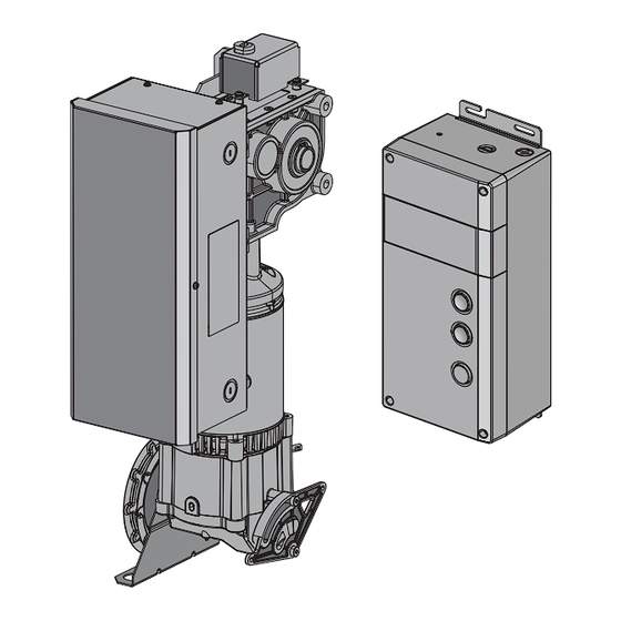
Page 41: Operator Dimensions
OPERATOR DIMENSIONS FRONT VIEW SIDE VIEW 9.37" 14.53" 23.8 cm 36.9 cm 9.23" 23.4 cm 16.19" 41.1 cm 14.28" 36.3 cm 10.1" 25.6 cm 14.28" 9.1 cm END VIEW VFD CONTROLLER DIMENSIONS: HEIGHT: 15.8 inches (40.13 cm) WIDTH: 7.42 inches (18.84 cm) DEPTH: 5.1 inches (12.95 cm) 11.31"... - Page 42 SERVICE PARTS Encoder Encoder cover Filter board Junction box cover Junction box Transformer Wall brace bracket Inverter board NOTE: Items 13-14: ‘Powerhead’ includes all parts shown. POWER HEAD SERVICE KIT DESCRIPTION K41-0165-000 Filter Board K41-0166-000 Transformer K41-0167-000 Inverter Board K41-0168-000 Junction Box K41-0169-000 Junction Box Cover...
- Page 43 SERVICE PARTS Tablero adaptador del relé Tablero de pantalla c/ pantalla Parte posterior de la caja de control Tablero de control Cubierta de la caja Ensamblaje de 3 botones de de control la caja de control NOTE: Item 7: ‘Door Control’ includes all parts shown. Controller Additional Items SERVICE KIT...
-
Page 44: Accessories
ACCESSORIES ENTRAPMENT PROTECTION DEVICES AND OTHER PARTS (CPS-UN4) PHOTOELECTRIC SENSORS EDGE SENSORS CPS-U Dual-Sided Infrared Photo Eyes: OES-RD16 Optical Edge System (OES): • NEMA 1 general purpose enclosure. 16 feet (4.9 m) Rolling 2-Wire Door Edge Kit with infrared optical sensors, rubber door edge and all •... -
Page 45: Warranty
WARRANTY LIFTMASTER LIMITED WARRANTY LiftMaster (“Seller”) warrants to the first retail purchaser of this product, for the residence in which this product is originally installed, that it is free from defects in materials and/or workmanship for a specific period of time as defined below (the “Warranty Period”). The warranty period commences from the date of purchase. - Page 46 © 2021, LiftMaster 114-5494B All Rights Reserved...
Need help?
Do you have a question about the Clopay HPH1 and is the answer not in the manual?
Questions and answers