Focusrite Saffire PRO 24 DSP - Multi-Channel FireWire Interface Manual
- User manual (34 pages)
Advertisement
- 1 Important Safety Instructions
- 2 Important Safety Precautions
- 3 Environmental Declaration
- 4 RoHS Notice
- 5 Introduction
- 6 Basics
- 7 Box Contents
- 8 Getting Started
- 9 Hardware
- 10 System Requirements
- 11 Installation
- 12 Windows
- 13 Mac OS
- 14 Audio Set-up in your DAW
- 15 Device Architecture
- 16 Saffire MixControl
- 17 Pre-amp Section
- 18 Mixer Section
- 19 Input FX Section
- 20 Reverb Section
- 21 Routing Section
- 22 VRM Section - Virtual Reference Monitoring
- 23 Monitor Section
- 24 Device Status section
- 25 Settings Menu
- 26 File Menu
- 27 Performance Specifications
- 28 Troubleshooting
- 29 Documents / Resources
Important Safety Instructions
- Read these instructions.
- Keep these instructions.
- Heed all warnings.
- Follow all instructions.
- Do not use this apparatus near water.
- Clean only with dry cloth.
- Do not block any ventilation openings. Install in accordance with the manufacturer's instructions.
- Do not install near any heat sources such as radiators, heat registers, stoves, or other apparatus (including amplifiers) that produce heat.
- Do not defeat the safety purpose of the polarized or grounding-type plug. A polarized plug has two blades with one wider than the other. A grounding type plug has two blades and a third grounding prong. The wide blade or the third prong are provided for your safety. If the provided plug does not fit into your outlet, consult an electrician for replacement of the obsolete outlet.
- Protect the power cord from being walked on or pinched particularly at plugs, convenience receptacles, and the point where they exit from the apparatus.
- Only use attachments/accessories specified by the manufacturer.
- Use only with the cart, stand, tripod, bracket, or table specified by the manufacturer, or sold with the apparatus. When a cart is used, use caution when moving the cart/apparatus combination to avoid injury from tip-over.
![]()
- Unplug this apparatus during lightning storms or when unused for long periods of time.
- Refer all servicing to qualified service personnel. Servicing is required when the apparatus has been damaged in any way, such as power-supply cord or plug is damaged, liquid has been spilled or objects have fallen into the apparatus, the apparatus has been exposed to rain or moisture, does not operate normally, or has been dropped.


To reduce the risk of fire or electric shock, do not expose this apparatus to rain or moisture.
It is important that the apparatus shall not be exposed to dripping or splashing and that no objects filled with liquids, such as vases shall be placed on the apparatus.
- Do not expose this apparatus to drips or splashes.
- Do not place any objects filled with liquids, such as vases, on the apparatus.
- Do not install this apparatus in a confined space such as a bookcase or similar unit.
- Slots and openings in the cabinet are provided for ventilation and to ensure reliable operation of the product and to protect it from overheating. Please ensure adequate space around the apparatus for sufficient ventilation. Ventilation should not be impeded by covering the ventilation openings with items such as newspapers, tablecloths curtains etc.
- The apparatus draws nominal non-operating power from the AC outlet with its POWER switch in the off position.
- The apparatus should be located close enough to the AC outlet so that you can easily grasp the power cord plug at any time.
- An apparatus with Class 1 construction shall be connected to an AC outlet with a protective grounding connection.
- The MAINS plug or the appliance coupler is used as the disconnect device. Either device shall remain readily operable when the apparatus is installed for use.
- No naked flames, such as lighted candles, should be placed on the apparatus.

excessive sound pressure levels from earphones and headphones can cause hearing loss.
This equipment must be earthed by the power cord
Important Safety Precautions

RISK OF ELECTRIC SHOCK
DO NOT OPEN
TO REDUCE THE RISK OF ELECTRIC SHOCK, DO NOT REMOVE COVER (OR BACK). NO USER-SERVICEABLE PARTS INSIDE. REFER SERVICING TO QUALIFIED SERVICE PERSONNEL.
 The lightning flash with arrowhead symbol, within equilateral triangle, is intended to alert the user to the presence of uninsulated "dangerous voltage" within the product's enclosure that may be of sufficient magnitude to constitute a risk of electric shock to persons.
 The exclamation point within an equilateral triangle is intended to alert the user to the presence of important operating and maintenance (servicing) instructions in the literature accompanying the appliance.
TO PREVENT FIRE OR SHOCK HAZARD, DO NOT EXPOSE THIS APPLICANCE TO RAIN OR MOISTURE
Environmental Declaration
Compliance Information Statement: Declaration of Compliance procedure
Product Identification: Focusrite Saffire PRO 24 DSP
Responsible party: American Music and Sound
Address: 5304 Derry Avenue #C
Agoura Hills,
CA 91301
Telephone: 800-994-4984
This device complies with part 15 of the FCC Rules. Operation is subject to the following two conditions:
- This device may not cause harmful interference, and
- this device must accept any interference received, including interference that may cause undesired operation.
RoHS Notice
Focusrite Audio Engineering Limited has conformed and this product conforms, where applicable, to the European Union's Directive 2002/95/EC on Restrictions of Hazardous Substances (RoHS) as well as the following sections of California law which refer to RoHS, namely sections 25214.10, 25214.10.2, and 58012, Health and Safety Code; Section 42475.2, Public Resources Code.
Introduction
If the main User Guide sections do not provide the information you need, be sure to consult http://www.focusrite.com/answerbase, which contains a comprehensive list of common technical support queries regarding the product to date.
Basics
The Saffire PRO 24 DSP hardware interface provides the means for connecting microphones, line-level signals, instrument-level signals, and digital signals to your computer, which are then routed to your audio recording software / digital audio workstation (referred to throughout this user guide as "DAW").
All audio signals connected to the inputs, plus audio output from your computer programs are routed to the physical outputs for you to connect to an amp and speakers, powered monitors, headphones, analogue/digital mixer, and any other studio equipment that you wish to use. There are also connectors for sending and receiving MIDI.
The accompanying software application, Saffire MixControl provides further recording, routing and monitoring options, as well as the ability to control global hardware settings such as sample rate and synchronisation.
Saffire MixControl software provides mixing and routing to and from the DAW, allowing control over which signals are sent from the sequencer to each output. All inputs on the Saffire PRO 24 DSP are routed directly to your DAW software for recording, but Saffire MixControl also allows you to route these signals to your monitors so that you can listen to the audio signals with zero latency - before they arrive at your DAW.
Saffire MixControl also provides control of the on-board DSP (digital signal processing). During the recording process, the DSP provides Compression and Equalisation on analogue inputs 1 and 2, as well as monitoring Reverb. During the mixing process, the DSP provides 'VRM' - Virtual Reference Monitoring, Focusrite's own loudspeaker and room simulator designed for headphone listening.
Box Contents
Along with your Saffire PRO 24 DSP you should have:
1 - 6 pin FireWire cable (also known as an IEEE1394 cable)
1 - Universal DC power supply unit (PSU).
1 - Installer CD: Contains combined installer for drivers and Saffire MixControl software for Mac and Windows.
Focusrite VST and AU Plug-in Suite for Mac and Windows - Includes:
Compressor
EQ
Gate
Reverb
4 - Self adhesive rubber feet - to be fitted to base of the Saffire PRO 24 DSP
1 - Registration Card
1- Excite Bundle - Includes:
Ableton Live LE version 7
Bass Station AU and VST synthesiser plug-in with Serial number card
Over a Gigabyte of "Loopmasters" and "Mike the Drummer" royalty free Samples
1 - Focusrite Product Brochure
1 - Novation Product Brochure
Getting Started
The Saffire PRO 24 DSP has a single 6 pin FireWire port on the back. This FireWire connection will work with any of the current FireWire standards and connectors; FireWire 400 (6 pin or 4 pin connection); and FireWire 800.
BEFORE YOU CONNECT THE Saffire PRO 24 DSP TO YOUR COMPUTER, PLEASE RUN THE INSTALLER. This will ensure that the correct drivers are used, thus preventing any unexpected behaviour
The Saffire PRO 24 DSP ships with a 6 pin FireWire cable. However on Windows laptops, the FireWire connection may be 4 pin FireWire. In this case you will need to purchase a 6 pin to 4 pin cable.
You may have a FireWire 800 connector on your computer. In this case you will need to purchase a 6 pin FireWire 400 to 800 cable or adapter.
The Saffire PRO 24 DSP can be powered via the FireWire connection when using 6 pin FireWire 400 or FireWire 800. When connected to a 4 pin FireWire you will need to use the supplied PSU.
Note:
FireWire considerations - Most computers will generally be equipped with 1 FireWire bus. You may have multiple FireWire ports (connectors) on your computer, but these are all connected to 1 physical chip which controls the bus.
The FireWire bus is limited in the amount of data bandwidth it can handle. Each additional FireWire device connected to the FireWire bus demands additional bandwidth resources, thus increasing the chances of exceeding the total available bandwidth. Consequently, it is recommended that Saffire PRO 24 DSP DSP run on its own FireWire bus for best performance.
The Saffire PRO 24 DSP should be able to work alongside other devices connected to the same FireWire bus. However, problems may arise depending on which FireWire devices are connected. For example, a FireWire disk used for back-up or a digital camera should not cause any problems, but when streaming audio from a FireWire hard disk or a FireWire box such as Focusrite Liquid Mix, the total FireWire bandwidth may be reached. This will result in audio drop outs, or reduced performance on either the Saffire PRO 24 DSP or the other connected FireWire device.
For this reason, we would recommend that you use a separate FireWire bus for each FireWire device. This may be a PCI / PCIe card in your desktop, or a PCMCIA or Express card in your Laptop.
In order to maximise the life of your FireWire ports, we recommend that you do not connect or disconnect your Saffire PRO 24 DSP whilst bus powered.
Hardware
Back Panel
The Back Panel provides the majority of input and output connections on the Saffire PRO 24 DSP.

- 2 x TRS jack sockets Line Inputs 3 and 4 *
- 6 x TRS jack sockets for Line Outputs 1-6 *
- 1 x Optical input socket **
- 1 x IEEE1394 6 pin FireWire socket
- 2 x Din5 MIDI Input and Output sockets
- 1 x Power switch
- 1 x 2.0mm DC Power inlet socket - Use supplied power supply only
- 2 x RCA SPDIF input and output sockets
* Either 1/4 inch TRS (balanced) or TS (unbalanced) Jack connectors can be used.
** Optical input can be used as either ADAT or S/PDIF optical input.
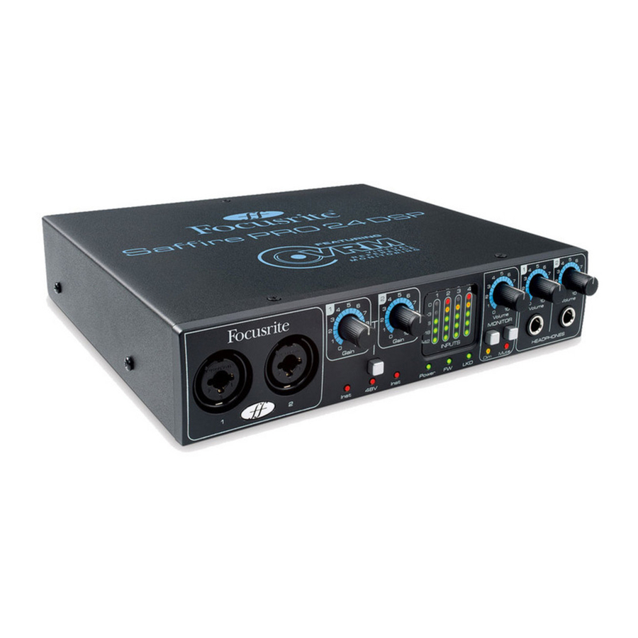
Front Panel
The Front Panel includes the input connectors for Mic, Line and Instrument signals, as well as the input gain controls and monitoring controls.

- Channels 1 and 2 with Combo XLR input sockets for Mic / Line / Instrument
- Channels 1 and 2 Gain control
- Channels 1 and 2 Instrument LEDs
- Phantom power switch with LED for Mic inputs 1-2
- Power LED - Lit when the unit receives power from FireWire or external power supply unit
- FW (Active) LED - Lit when the unit connects to the FireWire driver
- LKD (Locked) LED - Lit when the unit locks to its internal clock, or to an external clock source
- Separate 5 LED meter for each input channel -42, -18, -6, -3, 0
- Monitor Level control
- Monitor Dim and Mute switches with associated LED's
- Headphones 1 and 2 level control
- Headphones 1 and 2 output ¼" jacks
System Requirements
Macintosh
- OS: Mac OS X 10.4.11 or later
- Computer: Apple Macintosh with FireWire port
- CPU/Clock: PowerPC G4/1 GHz or higher (Intel/Dual 1 GHz or better recommended)
- Memory (RAM): 512 MB (1 GB or more recommended)
- Screen Resolution: 1024x768 (1280x1024 or more recommended)
Windows
- OS: Windows Vista (All Versions) or Windows XP SP2 or higher (All Versions)
- Computer: Windows compatible computer with FireWire port.
- CPU/Clock: Pentium or AMD with 1 GHz or higher (Dual 1 GHz or better recommended)
- Memory (RAM): 512 MB (1 GB or more recommended)
- Screen Resolution: 1024x768 (1280x1024 or more recommended)
Installation
We aim to ensure that the latest installation software will be on the disk included with your Saffire PRO 24 DSP. However we strongly recommend that you check for the latest version of software on our website; www.focusrite.com before starting to work with your Saffire PRO 24 DSP unit.
PLEASE ENSURE THAT YOU RUN THE INSTALLER BEFORE CONNECTING THE Saffire PRO 24 DSP TO YOUR COMPUTER
Windows
- Insert your installer disk into your computer's CD-ROM drive.
- You should see a window pop up showing the following installer icon: 'Saffire MixControl-1.5.exe'
- Double click on the installer icon to begin the installation process.
- Follow on screen instructions to complete the installation process.
- Note that the included VST plug-in suite installer will run after driver installation.
- Restart your computer.
- Connect the Saffire PRO 24 DSP to your computer.
Once the installation has been completed, your Computer OS should automatically switch its default audio outputs to be the Saffire PRO 24 DSP. To make sure this is the case:
On Windows Vista, go to Start > Control Panel > Hardware and Sound > Sound > Manage Audio Devices > Set Default 'Playback' and 'Recording' to 'Saffire Audio'.
On Windows XP, go to Start > Control Panel > Sounds, Speech and Audio Devices > Sounds and Audio Devices > Audio tab > Set Sound playback and recording to Saffire Pro Audio'.
Mac OS
- Insert your installer disk into your computer's CD-ROM drive.
- You should see a window pop up showing the following installer icons: 'Install Saffire MixControl.pkg'
- Double click on the installer icon to begin the installation process.
- Follow on screen instructions to complete the installation process.
- Restart your computer.
- Connect the Saffire PRO 24 DSP to your computer.
Once the installation has been completed, your Computer OS should automatically switch its default audio outputs to be the Saffire PRO 24 DSP. To make sure this is the case:
Go to System Preferences > Sound > Set the input and output to 'Saffire'.
For more detailed setup options on a Mac, go to Applications > Utilities > Audio Midi Set-up.
Note that the included VST and AU plug-in suite can be installed by running 'Focusrite Plug-in Suite.pkg' from the same installer disk.
Audio Set-up in your DAW
The Saffire PRO 24 DSP is compatible with any DAW that uses ASIO drivers on Windows, and any DAW that uses Core Audio on Mac.
Your DAW software may not automatically switch the device it uses to input and output audio.
You must ensure that you select 'Saffire' as the ASIO driver (Windows) or Core Audio driver (Mac) in your DAW's audio set-up page.
Please refer to your DAW's documentation if you are unsure where to select the ASIO / Core Audio driver.
Device Architecture
Saffire PRO 24 DSP offers more than just simple input and output routing to and from your computer. Saffire MixControl software also allows you to re-route audio signals to any output, and to create custom mixes to be sent to your recording artists, outboard processing equipment, or mixing console.
The following diagrams give an overview of the Saffire PRO 24 DSP audio paths when set at different sample rates and Optical input configurations.
The Hardware Inputs are routed directly to the DAW Inputs. The table below each diagram shows the routing configuration.

44.1kHz / 48kHz Optical as ADAT
| HARDWARE IN | DAW IN |
| Analogue 1-4 | 1-4 |
| S/PDIF 1-2 (RCA) | 5-6 |
| ADAT 1-8 (Opt) | 7-14 |
| Loop back 1-2 | 15-16 |

44.1kHz / 48kHz Optical as S/PDIF
| HARDWARE IN | DAW IN |
| Analogue 1-4 | 1-4 |
| S/PDIF 1-2 (RCA) | 5-6 |
| S/PDIF 3-4 (Opt) | 7-8 |
| Loop back 1-2 | 15-16 |

88.2kHz / 96kHz Optical as ADAT
| HARDWARE IN | DAW IN |
| Analogue 1-4 | 1-4 |
| S/PDIF 1-2 (RCA) | 5-6 |
| ADAT 1-4 (Opt) | 7-10 |
| Loop back 1-2 | 11-12 |

88.2kHz / 96kHz Optical as S/PDIF
| HARDWARE IN | DAW IN |
| Analogue 1-4 | 1-4 |
| S/PDIF 1-2 (RCA) | 5-6 |
| S/PDIF 3-4 (Opt) | 7-8 |
| Loop back 1-2 | 11-12 |
*DAW IN 9-10 are redundant
Saffire MixControl
The Saffire MixControl software allows flexible mixing and routing of all audio signals to the physical audio outputs, as well as control of output monitor levels. All sample rate selection, digital syncing and buffer size settings (Windows only) are available from Saffire MixControl.
To open Saffire MixControl.
Windows
Start > Programs > Focusrite > Saffire MixControl.
Mac
Open Finder > Applications > Saffire MixControl.
This is how the Saffire MixControl Graphical Interface will appear on your computer.

- Mixer
- Selected Mix Tab
- Mixer Input Channel
- Selected Mix Output Channel
- Routing and Pre-amp / Input FX / VRM Section
- Monitor Section
- Device Status Section
Pre-amp Section
When connecting a microphone to the Saffire PRO 24 DSP, you must connect an XLR cable to the combi inputs on the front panel. When connecting either Line level signal or Instrument signal to the combi inputs, you must select either Line or Inst from the preamp section.

The pre-amp settings can be accessed by selecting Router from the panel selection drop down menu.

The panel display is split to display the routing output settings in the top half, and the pre-amp settings in the bottom half.
Additional Line level signals can be connected to inputs 3 and 4 on the rear of the unit. The Preamp gain for Inputs 3 and 4 can be set to either Lo (low) or Hi (high) gain. The maximum input level before the signal will clip for each setting is as follows:
Low Gain: 0dBFS = +16dBu
High Gain: 0dBFS = -10dBV (~-6dBu)
Mixer Section
The Saffire MixControl software includes a total of 8 mixes, each with a maximum of 16 channels in the mix. Up to 8 mono mixes or 4 stereo mixes, (or any combination of mono and stereo mixes) are available, making up a total of 8 mixers.
Each Mix can contain up to 16 of the possible 24 inputs signals, and each mix can be sent to any number of outputs.
Each mix shares the same source inputs, but all other mixer controls are independent in each mix.
The Mixer Section is used to create mixes for monitoring purposes. The mixes you create do not affect how the audio inputs are routed to the DAW, nor does it affect the audio level of the signal to be recorded. What you set up in the mixer section of Saffire MixControl only affects what is heard in the outputs of the mix.
The recording levels that are sent to the DAW are therefore only affected by the input gain settings on the Saffire PRO 24 DSP, not the mixer.
The mixer section is useful for creating different simultaneous mixes. For example, you may wish to provide a headphone monitor mix for the recording artist which is different to the mix heard in the monitor speakers.
The artist needs to hear mainly the backing track, and a little of the recorded input signal. The engineer needs to hear mainly the recording artist's signal and a little of the backing track.
A separate mix can be created for both artist and engineer with the exact levels desired. Each independent mix is created on a different mix tab.
Mixer Tab

Each mix can be selected by clicking on the corresponding mixer tab.
Input Channel

Here is a picture of 2 mixer input channels. Below is a description of every component of a mixer channel.
Audio source select

When there is no input to a mixer channel, it will display "Off".

Clicking on the "Off" region brings up a list of all available inputs that can be fed to the channel. All analogue (labelled 'Anlg') and digital inputs, and DAW outputs are available.
When selecting a source on a stereo channel, if an odd numbered input is chosen for the left channel, the next even number input is auto selected for right, and Vice Versa
Note that if an input has already been taken, it will be greyed out and you cannot select it again. The input needs to be deselected from the track where it is already taken, and then re-selected on the desired track.
To get your sounds from your DAW or other computer applications into the mixer, you should select 'DAW 1' and 'DAW 2' on a stereo input track.
Pan Slider
A Pan Slider is used to position the audio signal anywhere between the left and right speakers.

Moving the horizontal slider from left to right will move the audio signal from left to right within the stereo field, i.e., the signal is faded between two audio outputs such as Line out 1 and 2. Hold down the Shift' key whilst moving the slider for fine control.
When used with a stereo track, the slider affects the audio signal such that when fully left, only the left channel is heard, and when fully right, only the right channel is heard
Fader

Use the fader to set the level of your audio signal for monitoring within the current mixer.
Click the fader with your mouse and drag to any position. Double click on the fader to set it to 0.
Hold the Shift Key to make fine adjustments to the fader value.
Fader range is from -∞ to +6 dB with the current fader level displayed in the box below.
Meter

The meter shows the signal level of the source input to the channel. The recent maximum signal level is displayed in the box below.
The metering is always pre-fade, showing the level of the signal at the input. Therefore, the fader level has no effect on the metering.
Clip light
If the red portion at the top of the fader lights up, then the signal level is too high.
You will need to turn down the signal level by either using the gain knobs on the front panel for the analogue inputs, using the gain on the external devices connected to the digital inputs, or using the gain within the DAW.
Once the gains are lowered, click on the red portion to reset the clip light.
Mute

Pressing this button mutes the signal. Red indicates that Mute is active.
Solo

Pressing this button solos the signal. The level of the fader will affect the level of the soloed signal.
Yellow Indicates that Solo is active.
PFL (Pre-fade listen)

Pressing this button solos the signal and automatically routes it to Monitor 1 and 2. The level of the soloed signal is pre- fade (i.e. it will not be affected by the level of the fader). Green Indicates that PFL is active.
Stereo

Pressing this button combines 2 mono channels into 1 stereo channel.
Track Name

As a default, each track is given a number as a name. Double click to rename the track to something more useful such as 'Vocal Mic'.
Mix Output Channel

The output channel of the mix is where all the input channels are routed to and mixed together. The output channel gives you control of the overall level of the entire mix. You can send a mix to any or all hardware outputs; if a single output is selected this is displayed at the top of the output channel. "Many..." will be displayed if multiple outputs are selected.
The output channel can be either mono or stereo depending on the status of the stereo button. When the channel is set to stereo, you will see that the tab for that mix doubles in size. This is due to the fact that the stereo version takes up 2 channels of the available total output channel count.
Note that when pressing on the solo button on an output channel, that channel (i.e. the whole mix) is soloed and routed to Monitor outputs 1 and 2. This is a non-latching button.
You can name the current mix by typing the desired name in the text field below the output channel. You will see the name appear in the mix tab. For example, Mix 1 can be renamed "Monitor Mix", and Mix 5 named "Headphone 1 Mix".
To copy an existing mix to another mix, simply click on "Copy Mix To..." and select the mix to which you would like to copy. Note that you can only copy a stereo mix to another stereo mix, and a mono mix to another mono mix. Therefore you must make sure that you have correctly set up the output channels to either stereo or mono before copying the mix.
Click on "Sel..." to view a drop down menu of the available output destinations for the selected mix (see the drop down menu in the screenshot below). Select an output in this menu in order to choose the output destination for the selected mix.

Input FX Section

The Saffire PRO 24 DSP can apply digital signal processing to both analogue inputs 1 and 2. The DSP consists of a Compressor and EQ effect for each channel.
Compressor
The Focusrite Compressor is modelled on the legendary Focusrite hardware devices, with individually tuned optos to help create the sound of vintage 1960s compression. The plug-in can be used to squash the dynamics of a sound in varying degrees, e.g. remove the sudden loud bursts, so that the overall level can then be turned up to make the signal as loud as possible. A compressor essentially acts like an automatic volume control, turning down the volume of a signal if it gets too loud. This reduces variation between loud and quiet passages, as it automatically reduces the gain when the signal exceeds a given volume, defined as the threshold. Using the Compressor helps to even out a performance, stopping a signal from clipping and/or disappearing in the mix, and can also give it a whole new sonic character.
The controls are:

COMPRESSOR ACTIVE Button - Click to turn the compressor on or off.

THRESHOLD Knob – Sets the level at which compression begins. The lower this value is set, the more of the signal will be compressed as the audio will compress when the threshold is reached. Rotate the TRSHLD dial anticlockwise to lower the threshold and so increase the compression.

RATIO Knob – Determines how much the signal is reduced by when it exceeds the threshold. For example, a ratio of 10:1 means that when the level of the uncompressed signal exceeds the threshold by 10dB, the compressed signal will only increase by 1dB. The higher the ratio therefore (the further the dial is rotated in a clockwise direction) the more heavily the signal is compressed.

GAIN REDUCTION Meter – Indicates when compression is occurring by showing the gain reduction applied to the signal.

ATTACK Knob – Defines how quickly the compressor kicks in, e.g. how fast the signal is turned down when it exceeds the threshold. In other words, setting a slower/longer attack time by rotating the dial clockwise will mean more of the loud part of the signal gets through uncompressed, which makes the signal much more punchy but also more likely to clip.

RELEASE Knob – Defines how quickly the compressor stops acting on the signal after it has begun to compress. Setting a quicker/shorter release time by rotating the dial anticlockwise will normally make the signal louder overall, however this is dependant on the attack time and amount of time the signal is above the threshold.

OUTPUT Knob – Defines how much the level of the compressed signal is increased after compression. This means that a heavily compressed signal can be turned up loud to give greater perceived loudness without the risk of clipping.
EQ
Equalisation of sound is an essential part of the recording process, necessary to remove or boost specific sections of the audible frequency spectrum. The Focusrite EQ is 4-band, with 2 fully parametric mid bands and the option of shelving or high-pass / lowpass on bands 1 and 4, and exhibits the same curves as the classic Focusrite EQ.
The two central bands have the same 3 knobs for modifying parameters: Frequency, Gain and Q. When high and lows bands are in high-pass or low-pass mode (switch in lower position), the Gain knob changes into Q. This is because there is no cut or boost option with a high-pass or low-pass filter, just a slope of variable Q at a selected cut-off frequency. The shelving mode doesn't require a Q control because the slope is fixed.
The controls are:

EQ ACTIVE Button - Click to turn the EQ on or off.

FREQUENCY Knobs – Set the frequency that the band affects, e.g. the centre frequency in bell mode, the cut-off frequency in high-pass /low-pass mode or the start of the shelf in shelving mode.

GAIN Knobs – Increase or decrease the level of the corresponding band of EQ. The band will have no effect with the knob in a central position. Rotate clockwise to increase and anticlockwise to decrease the level by up to 18dB.

Q Knobs – Set the level of resonance of the band, making the band have a more pronounced effect. Increasing Q decreases the bandwidth so that the bell acts on less of the frequency range.

SHELVING/HIGH-PASS or LOW-PASS Switch – Selects a low-shelf (upper) or high-pass (lower) for band 1, and a highshelf (upper) or low-pass (lower) for band 4.

OUTPUT Knob – Increases or decreases the level of the signal at the EQ output. No gain modification occurs with the knob in a central position. Rotate clockwise to increase and anticlockwise to decrease the level by up to 36dB.
Additional Controls

FX Chain Order Button - Click to change the order in which Compressor and EQ are chained. If the Compressor is positioned above the EQ, the signal is compressed before EQ. With EQ positioned above the Compressor, EQ is applied before compression.

FX Mono / Stereo Button - Click to switch between 2 channel Mono and 2 channel Stereo operation. When in Stereo mode, FX controls for input 2 on the right are unavailable. All parameter settings are set on the Left channel but are applied to both Left and Right channels. Note that when in Stereo Mode, the Compressor works in True Stereo - i.e. equal compression is applied to both channels.

Input / Output Meters - Display the signal level directly before and after Compression and EQ.
Monitoring with or without FX
Saffire MixControl allows monitoring of Inputs 1 and 2 with or without FX.

When selecting an Input source in the Mixer or Routing section, the dry signal is represented by 'Anlg In 1' and 'Anlg In 2', and the wet signal as 'FX(Anlg 1)' and 'FX(Anlg 2)'.
Recording with or without FX
The signal routing can be setup so that analogue inputs 1 and 2 can be recorded to the DAW with or without the DSP FX.
When you select input 1 and 2 in your DAW software, the input signal with DSP is recorded (when the DSP FX are active).

To record inputs 1 and 2 without DSP FX, you must use the Loopback feature which is available from the Routing Panel.
The loopback inputs should be set to 'Anlg In 1' and 'Anlg In 2'
When 'Anlg In 1' and 'Anlg In 2' are routed to Loopback, these will be available to record in your DAW via the Loopback input channels.
As defined in the diagrams on pages 10 and 11, the Loopback channels will appear in your DAW as inputs
15, 16 @ sample rates of 44,1kHz, 48kHz
11, 12 @ sample rates of 88,2kHz, 96kHz
Reverb Section
Reverberation is an effect that enables a sound source to be placed in an environment. It does this by adding a reverberant tail of reflected sound, the properties of which correspond to a space of varying dimensions.

Click on the Reverb Send Mixer tab to access Reverb send settings and Reverb Controls.
The level of the faders of each of the mixer channels determines the signal level being sent to the reverb unit.
In the above picture, only channel 1 - 'FX(Anlg1)' is being sent to the reverb.
The Reverb controls are:

REVERB ACTIVE Button - Click to turn the reverb on or off.

SIZE Knob – Defines the size of the reverberant space. Rotate clockwise to increase. Increasing the size makes the reverberation greater, e.g. more time between initial sound and early reflections, plus longer decay time

PRE-FILTER Knob – Acts as a high- or low- pass filter for the reflected sound (removes the bass or treble, respectively). Rotate anti-clockwise to produce a low-pass filter effect, where the maximum cutoff (lowest frequency) is set in the extreme anticlockwise position. Rotate clockwise to create a high-pass filter effect, with the maximum cutoff (highest frequency) is set in the extreme clockwise position. In the centre, no filtering of the reflected sound occurs

AIR Knob – Sets the amount of absorption (or damping) of reflected sound (the more absorption, the less 'airiness'). In a fully anticlockwise position, absorption is at a maximum so there is very little air. Rotate clockwise to decrease absorption and increase 'air'
Reverb Return

Each Mixer (Mix 1 - 8) includes a Reverb Return channel.
Set the fader level of the reverb return channel to determine how much of the reverberation signal is to be sent to the output of that mix.
Routing Section

The routing section allows you to set up which audio sources are routed directly to which physical outputs.

The routing section displays every physical output on the Saffire PRO 24 DSP and the audio stream to be sent to that output is available for selection in a drop down menu to the left of that output.
Clicking on the box to the left of the output label will bring up a list of all available audio output sources.
The available sources include:
- All input streams (Analogue 1-4, S/PDIF, ADAT)
- All DAW playback stream (DAW 1 - 8)
- All mixes from the mixer (Mix 1 - 8)
If you have named the mix (by clicking in the track name section – see previous chapter) then this name is displayed as the mix source name.
Note that the routing section is linked to the selection made for the output channel destination set-up in the mixer. If you have outputs pre-assigned from when you created your Mix, you will see the routing selections have been set up. Similarly, if you change the audio source from the routing section, the output of the mix will change automatically.
'Headphones 1' is a copy of line outputs 3 and 4. All audio routed to Line outputs 3 and 4 will be heard in Headphone 1 Left and Right.
'Headphones 2' is a copy of line outputs 5 and 6. All audio routed to Line outputs 5 and 6 will be heard in Headphone 2 Left and Right.
When working at sample rates of 88.2kHz or 96kHz, the total number of ADAT channels available drops to 4 channels "ADAT SMUX". At these sample rates, ADAT channels 5-8 for the ADAT connection are greyed out.
Routing Presets

Routing Presets are provided as a starting point for you to create your own routing and mixer set-ups.
These will enable you to quickly set up your routing for recording (monitoring your inputs); mixing (sending signals out to outboard processors or external mixer); or internal looping (routing audio between software applications without leaving the computer).
Clear
This turns off all output routing. This can be used to re-set the routing for when you need to completely restart a configuration, meaning you do not have to manually turn everything off first.
DAW Tracking
'DAW Tracking' is used for the initial recording process. It will automatically output DAW 1 and 2 to be sent to all Line outputs and hence your main monitors (1+2) and to Headphone outputs 1 and 2. All input channels must be monitored from within the DAW application.
Zero Latency Tracking
Zero Latency Tracking is used for the recording process. It will automatically output Mix 1 and 2 to all your Line outputs simultaneously, and hence will route to the main monitors (1+2), and to the Headphone outputs 1 and 2. Line inputs and DAW outputs must be set up in Mix 1 so that you are able to monitor these sources with zero latency. You must also ensure that you are not monitoring the same signals from within your DAW at the same time, otherwise you will be monitoring the same signal twice (once direct from Saffire MixControl AND a second time (with latency) from your DAW.)
Mixing
'Mixing' is used for the mixing process. When sending signals out to a mixer or to external processing hardware, hardware outputs are typically set exactly as they are set in the DAW software. DAW outputs route directly to the line output of the same number. (DAW outputs 1-6 to Line outputs 1-6.)
Loopback
Use when recording from one software program to another. You can use loopback routing to record audio from e.g. your internet browser into your DAW, or to record from one DAW to another.
To prevent any audio feedback, make sure that the DAW you are recording into is not set to monitor its inputs. Alternatively, set the outputs of the DAW into which you are recording to 3 and 4; this allows you to monitor the inputs without feeding the signal back into the record stream.
VRM Section - Virtual Reference Monitoring
Technical Information
VRM is a system that simulates the acoustics of loudspeakers and listening rooms for reproduction over headphones. A correct sense of stereo image, perspective, and environment is normally absent in headphone reproduction. VRM provides these aural cues for effective reference monitoring for mixing on headphones.
The VRM system works by combining three separate modeling and measurement processes:
The speaker emulations were achieved by sending test signals through the original speaker and then taking many measurements through a reference microphone placed at varying positions and distances from the speaker. This process allows the creation of a three-dimensional model of how each speaker radiates sound.
The listening environments were not obtained from real rooms, but built using computer models. The model includes not just room dimensions but also the information about how sound is absorbed and reflected by the floor, walls, and ceiling. Also included in the model is the furniture found in each environment. This computer model allows the fine-tuning of the environment to produce the most comfortable listening experience.
To complete the simulation, we obtained a set of head-related transfer functions – models of how sound arrives and is heard in both ears of a human head. Thousands of measurements were combined to create a model of how direct and reverberated sound arrive at the two ears.
The three listening environments available are a Professional Studio, Living Room, and Bedroom Studio. The following table shows which speaker models and listening positions are available in each environment.
| Room Model | Speaker Models | Listening Positions (all of these speakers) |
| Professional Studio | Japanese White Classic US Yellow Cone Vintage Wooden Cube US Passive Nearfield British Studio Finnish Studio US Yellow Cone Pro German Studio Ribbon Vintage Broadcast Modern Broadcast | centre (at 1.65m from speakers); 7.5cm left; 15cm left; 7.5cm right; 15cm right; 80cm back. |
| Living Room | British 90s Hi-Fi British 80s Hi-Fi Flat-screen Television Finnish Studio New Broadcast | centre (at 1.8m from speakers); 45cm left; 90cm left; 45cm right; 90cm right; 1.2m back and 45cm left; 1.2m back and 45cm right. |
| Bedroom Studio | US Yellow Cone British 90s Hi-Fi British 80s Hi-Fi Computer Desktop Budget Micro System Flat-screen Television Finnish Studio US Yellow Cone Pro New Broadcast | centre (at 1.4m from speakers); 30cm left; 30cm right; 50cm back; 50cm back and 50cm left; 50cm back and 50cm right. |
Listening Environment Data
| Listening Environment | Dimensions | Volume | Reverb Time |
| Professional Studio | 6.10 x 6.48 x 3.53 m | 139.40 m³ | 0.38 s |
| Living room | 5.48 x 4.66 x 2.79 m | 71.27 m³ | 0.36 s |
| Bedroom Studio | 3.28 x 3.69 x 2.47 m | 29.90 m³ | 0.47 s |
Loudspeaker Emulation Data
| Emulation Name | Based On: | Size (cm) | Tweeter | Woofer | System |
| German Studio Ribbon | ADAM S2.5A | 45H, 28W, 30D | Ribbon | 8" | Active 2-way bass reflex |
| US Passive Nearfield | Alesis Monitor One | 38H, 22W, 24D | 1" silk dome tweeter w/ ferrofluid cooling | 6.5" mineral-filled polypropylene cone | Passive 2-way rear firing port |
| Vintage Wooden Cube | Auratone 5C | 17H, 17W, 14D | [none] | 4" | Passive single driver closed box |
| British 80's Hi-Fi | B&W DM12 | 34H, 22W, 26D | 1" polyester weave dome | 6" bass/midrange driver | Passive 2-way closed box |
| Computer Desktop | Creative S8S35 | 15H, 8W, 10D | (none) | 2.5" | Active single driver rear firing port |
| Finnish Studio | Genelec 1031A | 49H, 25W, 29D | 1" metal dome | 8" poly composite driver | Active 2-way vented box |
| Budget Micro System | Goodmans MS188 | 28H, 18W, 19D | 1" dome | 3.5" | Passive 2-way ported box |
| British 90's Hi-Fi | KEF Q55.2 | 85H, 21W, 25D | 1" | 5" | Passive 2-way rear ported box with passive radiator |
| US Yellow Cone | KRK RP6 G2 | 33H, 22W, 27D | 1" neodymium soft dome with ferrofluid | 6" glass aramid composite | Active 2 way front firing ported box |
| US Yellow Cone Pro | KRK VXT8 | 44H, 32W, 30D | 1" silk dome ferrite | 8" woven kevlar | Active 2 way front firing ported box |
| Flat-Screen Television | Phocus LCD 26 TV | 45H 87W 10D (Stereo TV) | [none] | 2" x 4" oval-shaped driver | Active single driver |
| British Studio | Quested S8 | 42H, 30W, 35D | 1" soft dome | 8" cone | Active 2-way bass reflex |
| Vintage Broadcast | Rogers LS3/5a | 30H, 19W, 16D | 0.75" | 5" KEF B110 | Passive 2 way closed box |
| New Broadcast | Stirling LS3/5a | 30H, 19W, 16D | 0.75" | 5" KEF B110 | Passive 2 way closed box |
| Japanese White Classic | Yamaha NS-10M Pro | 38H, 22W, 18D | 1.5" | 7" cone | Passive 2 way closed bookshelf |
* IMPORTANT INFORMATION: FOCUSRITE, the FF logo, VRM Virtual Reference monitoring and the VRM logo are trademarks of Focusrite Audio Engineering Ltd.
All other product names, trademarks, or trade names are the names of their respective owners, which are in no way associated, connected nor affiliated with Focusrite or its Saffire PRO 24 DSP product and which have not endorsed Focusrite's Saffire PRO 24 DSP. These other product names, trademarks, and trade names are used solely to identify and describe the third party loudspeaker systems, the sonic behaviour of which was studied for the VRM technology incorporated within the Saffire PRO 24DSP, and to accurately describe an element of functionality within the Saffire PRO 24DSP.
The Saffire PRO 24DSP is an independently engineered technology which utilises Focusrite's VRM Virtual Reference Monitoring (Patent applied for) to actually measure examples of the sonic impact of original loudspeaker systems upon an audio stream, so as to electronically emulate the performance of the original product studied. The result of this process is subjective and may not be perceived by a user as producing the same effects as the original products studied.
Using VRM

Select VRM from the panel select drop down list
Once selected, the following panel will be shown:


Click on the power button to turn VRM On or Off.

Click on the arrow to select the listening environment

The green dot indicates the current listening position. Click in any empty circle to select a new listening position. Note that only certain listening positions are available for each listening environment (see table

Click on the down arrow to select the monitor speaker. Note that only certain monitor speakers are available in each environment (as shown in the table above.)

Click on the 'i' button to display information on the listening environment, listening postion and monitor speakers.
The following information will be displayed.

Environment and Speaker information is the same as found in the tables.
Coordinates information is described as follows:
Spkr-sep: The distance between the two speakers.
X-Offset: The distance from the 'Sweetspot' listening position. A + value is to the Right, a - value is to the Left.
Y-Offset: The distance from the 'Sweetspot' listening position. A + value is to the Front, a - value is to the Rear.
L- Angle: The angle between the listening position and the Left speaker
R- Angle: The angle between the listening position and the Right speaker
L- Dist: The distance between the listening position and the Left speaker
R- Dist: The distance between the listening position and the Right speaker
VRM is applied to Headphone output 1. No VRM processing is applied to Headhone output 2. As Headphone 1 shares the same output stream as Line outputs 3 and 4, a VRM processed signal will be sent to these Line outputs. As VRM is specifially designed to work with headphones, using VRM on Line ouputs will not give an accurate model.
Monitor Section

The output levels of the monitor outputs and line outputs are configured in the Monitor Section. You can set up your Saffire PRO 24 DSP so that the hardware 'Monitor' knob on front panel of the Saffire PRO 24 DSP will control the desired outputs, such as your stereo monitors, your surround sound system. Alternatively the 'Monitor' knob be deactivated for specific outputs e.g. when volume control is required for a pair of monitor speakers, but not for additional outputs being sent to e.g. an external compressor. Additional controls such as mute, dim and mono are available.
Monitor control enable buttons (1 to 6)

The monitor control enable buttons indicate which outputs are controlled by the monitor section on the GUI directly below the six buttons. The Saffire PRO 24 DSP has two levels of monitor volume control. The software monitor knob can be used to control the level of up to 6 outputs simultaniously. However the physical monitor knob controls the level of outputs 1 and 2 (post software control).
(All digital output levels are unaffected by the monitor section in Saffire MixControl. Use the output levels of the DAW to control digital output levels.)
Each button can be set to 1 of 3 possible states:

Blue - this output is controlled by the below monitor section.

Red - this output is not controlled by the below monitor section and it is muted.

Grey - this output is not controlled by the below monitor section and it is at full level.
To set a button to its Grey state, SHIFT + Click the button.
When a Monitor control button is set to 'Grey', the signal routed to that output will be played back at full level.
This may potentially result in a very loud signal being sent to your monitor speakers, headphones or other equipment.
Be cautious when setting your levels (in your DAW or the Saffire MixControl Mixer) before setting the monitor button to Grey.
Monitor Presets drop-down menu

These presets allow quick changing of typical monitoring set-ups.
For the monitor presets to work, you must have your speakers connected to the line outputs as shown in the picture below.

Surround Sound Monitoring: Quad, 2.1, or 5.1.
| Line out | Speaker |
| 1 | Left |
| 2 | Right |
| 3 | Centre |
| 4 | Sub Woofer |
| 5 | Left Rear |
| 6 | Right Rear |

Loudspeaker Set-up: Main, Mid, Mini
| Line out | Speaker |
| 1 | Left Main |
| 2 | Right Main |
| 3 | Left Mid |
| 4 | Right Mid |
| 5 | Left Mini |
| 6 | Right Mini |
Monitor Presets
| Preset Name | Output |
| Off - no Monitor control buttons enabled, therefore no sound will come out of any analogue output. | |
| Mono - outputs only to the Centre / mono speaker (Line output 3.) All other channels are muted. | Output - 3 |
| Stereo - outputs to Stereo speakers (Monitor 1 and 2 output.) All other channels are muted. | Outputs - 1,2 |
| Quad - outputs to Monitor 1 and 2 outputs and Line 5 and 6 outputs. All other channels are muted. | Outputs - 1,2,5,6 |
| 2.1 Surround - outputs to Stereo speakers (Monitor 1 and 2 output) and Sub (Line output 4). | Outputs - 1,2,4 |
| 5.1 Surround - outputs to all 5.1 speakers. All other channels are muted. | Outputs - 1,2,3,4,5,6 |
| Mid + Phones 1 - outputs to Mid Speakers and Headphones 1. | Outputs - 3,4 |
| Mini + Phones 2- outputs to Mini Speakers. and Headphones 2. | Outputs - 5,6 |
Monitor Section Controls
The following controls in the Monitor Section will affect those channels that have been selected for monitor control (indicated with a blue button, see above.)
Monitor level control knob

Set the output level of all assigned outputs using this knob. The output level can be adjusted using the mouse and will affect all assigned outputs (as indicated with a blue button). The dB display below shows the current level to which the monitor knob is set.
Note that the front panel Monitor control affects only outputs 1 and 2, and is an additional volume control on top of the monitor level set in Saffire MixControl software.
Dim switch

Attenuates the output level by 18dB.
Mute switch

Mutes the output.
Left Mute switch

Mutes the left output.
Right Mute switch

Mutes the right output.
Remember that these dim, mute and mono buttons only affect the outputs selected for control (i.e. Blue) in the monitor control section.
Device Status section

The Device Status section shows information about the sample rate, synchronisation and driver status of the Saffire PRO 24 DSP. The desired sample rate can be set as well as external synchronisation options for using the Saffire PRO 24 DSP with external digital devices.
Sample rate display
This displays the current Sample rate at which the Saffire PRO 24 DSP is running. To change the Sample rate, click on the red sample rate value and select 44.1kHz, 48kHz, 88.2kHz, or 96kHz,
Note: it is must quit your DAW application BEFORE you make sample rate changes to prevent any undesirable side-effects in your DAW!
Sync Source display

Displays the currently selected sync source (red display) – To change the sync source, click on the red sync source value and select SPIDF -OPT, SPDIF, ADAT, or Internal.
Sync source locked display
Displays "Locked" when the Saffire PRO 24 DSP has successfully locked to the specified Sync Source.
If "No Lock" is seen, then the unit has been unable to lock to either an external ADAT or S/PDIF signal. If this is the case, then please check that digital cables are secure in their input sockets, and that the external digital devices have been set up as master devices.
FireWire Driver
This should display "Connected" at all times when the Saffire PRO 24 DSP is connected to the computer via FireWire. If this shows "Disconnected" please check FireWire connections, check that the unit is switched on etc. If it still shows "Disconnected" then restart the computer and then restart the Saffire PRO 24 DSP.
Unit Name Text Field
Allows naming of the Saffire PRO 24 DSP unit. Double click in the field and enter your text. Press enter (return) on your computer keyboard to complete.
FireWire Driver In Use

When the Audio Applications are open and using the Saffire PRO 24 driver, the FireWire Driver Status will show 'In Use'. Various Settings will be unavailable until the Audio applications have been closed and the FireWire Driver Status and reverted to 'Connected'.
Settings Menu
This is a drop down menu containing all of the following items which allow you to set up different global/system configurations.
This is the only part of Saffire MixControl software where there are differences between the Windows and Mac versions.

Mac

Windows
Use Optical ADATs as S/PDIF
Here you can set the format of the optical digital input socket. It can either be an ADAT stream or an S/PDIF stream. (Useful for those who have S/PDIF equipment that only has an optical connector.)
S/PDIF AC3
Allows the user to stream AC3 directly via the S/PDIF outputs. (AC3 is encoded 5.1 audio, e.g. from a DVD player, that will be sent via S/PDIF cable (RCA or Optical) to your 5.1 decoder.)
Firewire Driver Latency

The Saffire PRO 24 DSPs latency performance will be dictated by the Core Audio buffer size specified in your DAW (Mac,) or as set in the ASIO buffer size (Windows.) The Firewire Driver Latency affects the performance of the Core Audio or ASIO buffer settings.
If you are experiencing clicks and pops or audio dropouts, this may be due to certain hardware in your computer that is affecting the performance of audio devices connected via FireWire. Rather than removing and replacing hardware (e.g. your graphics card or wireless internet card) trying a longer Firewire Driver Latency setting may solve the problem.
Disable WDM Audio in Windows (Windows Only)
Tick this option to ensure that only audio from your DAW is played through the Saffire PRO 24 DSP. Windows sounds will not be played through the Saffire PRO 24 DSP. Sounds from other software will not be played through the Saffire PRO 24 DSP. This is useful to prevent any unwanted audio being heard when you are working in your DAW. It is especially useful when other applications output audio at a sample rate different from the sample rate at which your DAW is operating.
ASIO Buffer Size (Windows Only)

Set the buffer size of your ASIO driver here.
A small buffer size will in result in lower latency at the expense of increased CPU usage. A high buffer size will result in a higher latency but with lower CPU usage. If you are using lots of virtual instruments and effects processing in your DAW project, and the CPU usage is high, then increase the buffer size to permit lower CPU usage.
File Menu

Mac

Windows
Open - opens a File open dialog allowing selection of any pre-saved Saffire MixControl set-ups.
Save - opens a File save dialog allowing selection of a location into which your Saffire MixControl set-up can be saved. Subsequent saves overwrite the original file.
Save As - opens a File save dialog allowing selection of a location into which your Saffire MixControl set-up can be saved. Use this option if you want to keep your original saved set-up and create a new one with a different name.
Restore Factory Default - Causes the Saffire PRO 24 DSP to revert to the original default state in which it left the factory. This can be used to globally reset all mixer, routing, and monitor settings, allowing creation of a new set-up from scratch.
Clear all Settings - Causes the Saffire PRO 24 DSP to reset all settings.
Save to Hardware - This saves the current Saffire MixControl set-up to the Saffire PRO 24 DSP hardware. If you are moving the Saffire PRO 24 DSP from one computer to another and want to retain the set-up, then choose this option. Note that Saffire MixControl does not automatically load from hardware (as this would overwrite a current set-up); it must be loaded manually.
Load from Hardware - This loads the saved set-up from the Saffire PRO 24 DSP hardware into the Saffire MixControl software.
As you can see from the above screen shots, 'Open', 'Save' and 'Save as' all have keyboard shortcuts. These are standard shortcuts for their respective functions, so if you are regularly changing settings for your various sessions, then the shortcuts will reduce your set-up time.
Performance Specifications
Microphone Inputs 1-2
- Frequency Response: 20Hz - 20kHz +/- 0.1 dB
- Gain Range: +13dB to +60dB
- THD+N: 0.001% (measured at 1kHz with a 20Hz/22kHz bandpass filter)
- Noise EIN: 124dB analogue to digital (measured at 60dB of gain with 150 Ohm termination (20Hz/22kHz bandpass filter)
- Input Impedance: 2k Ohm
Line Inputs (Inputs 1-2)
- Frequency Response: 20Hz - 20kHz +/- 0.1dB
- Gain Range: -10dB to +36dB
- THD+N: < 0.001% (measured with 0dBFS input and 22Hz/22kHz bandpass filter)
- Noise: -90dBu (22Hz/22kHz bandpass filter)
- Input Impedance: >10k Ohm
Line Inputs 3-4
- Frequency Response: 20Hz - 20kHz +/- 0.1 dB
- Gain Range: Switch-able between +16dBu or -10dBV for 0dBFS (balanced inputs)
- THD+N: 0.003% (measured at 1kHz with a 20Hz/22kHz bandpass filter)
- Noise: -100dBu (22Hz/22kHz bandpass filter)
- Input Impedance: >10k Ohm
Instrument Inputs (Inputs 1 and 2)
- Frequency Response: 20Hz - 20kHz +/- 0.1dB
- Gain Range: +13dB to +60dB
- THD+N: 0.004% (measured with 0dBu input and 20Hz/22kHz bandpass filter)
- Noise: -87dBu (20Hz/22kHz bandpass filter)
Analogue Audio Outputs (Outputs 1-6)
- 6 Electronically Balanced Outputs
- Maximum Output Level (0dBFS): +16dBu
- THD+N: 0.001% (0dBFS input, 20Hz/22kHz bandpass filter)
Digital Performance
- A/D Dynamic Range = 105dB (A-weighted), all analogue inputs
- D/A Dynamic Range = 105dB (A-weighted), all analogue outputs
- Clock Sources:
Internal Clock
Sync to Word Clock on SPDIF Input (RCA)
Sync to Word Clock on ADAT input
Sync to Word Clock on optical SPDIF Input (when enabled) - JetPLL™ PLL technology providing superb jitter reduction for class leading converter performance.
- Clock jitter < 250 picoseconds
- Supported Sample Rates: 44.1kHz, 48kHz, 88.2kHz, 96kHz
- 16 input channels to computer: Analogue (4), SPDIF (2), ADAT (8) and Mix Loop-back (2).
- 8 output channels from computer: Analogue (6), SPDIF (2).
- Assignable 16 input by 8 output mixer.
Front and Rear Connectivity
Analogue Channel Inputs (Inputs 1-4)
- 2 Mic XLR Combo (channels 1-2) on front panel
- 2 Line ¼" TRS (channels 3-4) on rear panel
- Automatic switching between Mic / Line (channels 1-2)
- Switching between Line / Instrument Inputs (channels 1-2) via Saffire MixControl Application
- Switching between +16dBu (low) and -10dBV (high) gain on inputs 3-4 via Saffire MixControl Application
Digital Channel Inputs (Inputs 9-26) 44.1 - 96kHz
- Stereo S/PDIF input on RCA
- 8 ADAT inputs on Optical Connector, reduces to 4 inputs at 88.2/96kHz
- Optical ADAT Input can be switched to S/PDIF 3/4 in software preferences (ADAT Input disabled)
Analogue Audio Outputs (Outputs 1-6)
- 6 ¼" TRS Jacks
- Output Level control (analogue) for outputs 1 and 2
- Stereo Headphones Mix 1 on ¼" TRS (also routed to Outputs 3 & 4) with VRM and independent volume control
- Stereo Headphones Mix 2 on ¼" TRS (also routed to Outputs 5 & 6) with independent volume control
Digital Channel Outputs (Outputs 8-9) 44.1 - 96kHz
- Stereo S/PDIF Output on RCA
Other I/O
- 1 6-pin FireWire S400 socket
- 2 Standard 5-pin DIN MIDI connectors: In and Out
- DC Power Input Connector (for use with supplied universal input power supply)
Front Panel Indicators
- 4 5 segment input meters, -42, -18, -6, -3 and 0dBFS
- LKD "Lock" Indicator
- FW "Host Connected" Indicator
- "Power" LED
- Instrument input source selection LED for channels 1 and 2
- 48 V Phantom Power LED
- Dim and Mute LEDs
Weight and Dimensions
- Dimensions: approx. 21.5 x 4.5 x 22cm (W x H x D)
- Weight: 1.5kg
Troubleshooting
For all troubleshooting queries, please visit the Focusrite Answerbase where there are articles covering numerous troubleshooting examples. www.focusrite.com/answerbase.
E & O.E.

Documents / Resources
References
Download manual
Here you can download full pdf version of manual, it may contain additional safety instructions, warranty information, FCC rules, etc.
Download Focusrite Saffire PRO 24 DSP - Multi-Channel FireWire Interface Manual
Advertisement


Need help?
Do you have a question about the Saffire PRO 24 DSP and is the answer not in the manual?
Questions and answers