Fujitsu AirStage ARXC45GATH Installation Manual
Hide thumbs
Also See for AirStage ARXC45GATH:
- Design & technical manual (1124 pages) ,
- Service manual (255 pages) ,
- Operating manual (6 pages)
Table of Contents
Advertisement
Quick Links
ARXC36GATH
ARXC45GATH
ARXC60GATH
TM
INSTALLATION MANUAL
INSTALLATIONSANLEITUNG
MANUEL D'INSTALLATION
MANUAL DE INSTALACIÓN
Únicamente para personal de servicio autorizado.
MANUALE DI INSTALLAZIONE
A uso esclusivo del personale tecnico autorizzato.
ΕΓΧΕΙΡΙΔΙΟ ΕΓΚΑΤΑΣΤΑΣΗΣ
ΕΣΩΤΕΡΙΚΗ ΜΟΝΑΔΑ (Τύπος Αγωγού)
Μόνο για εξουσιοδοτημένο τεχνικό προσωπικό.
MANUAL DE INSTALAÇÃO
UNIDADE INTERIOR (Tipo de tubagem)
РУКОВОДСТВО ПО УСТАНОВКЕ
Только для авторизованного обслуживающего персонала.
Refer to the rating label with the serial number.
INDOOR UNIT (Duct Type)
For authorized service personnel only.
INNENGERÄT (Kanaltyp)
Nur für autorisiertes Fachpersonal.
UNITÉ INTÉRIEURE (type conduit)
Pour le personnel agréé uniquement.
UNIDAD INTERIOR (Tipo conducto)
UNITÀ INTERNA (tipo a condotto)
Apenas para técnicos autorizados.
ВНУТРЕННИЙ МОДУЛЬ (Короб)
MONTAJ KILAVUZU
İÇ ÜNİTE (Kanal Tipi)
Yalnızca yetkili servis personeli için.
MADE IN THAILAND
[Original instructions]
PART NO. 9373870227
Advertisement
Table of Contents

Related Manuals for Fujitsu AirStage ARXC45GATH


Summary of Contents for Fujitsu AirStage ARXC45GATH
- Page 1 INSTALLATION MANUAL INDOOR UNIT (Duct Type) For authorized service personnel only. INSTALLATIONSANLEITUNG INNENGERÄT (Kanaltyp) Nur für autorisiertes Fachpersonal. MANUEL D’INSTALLATION UNITÉ INTÉRIEURE (type conduit) Pour le personnel agréé uniquement. MANUAL DE INSTALACIÓN ARXC36GATH ARXC45GATH UNIDAD INTERIOR (Tipo conducto) ARXC60GATH Únicamente para personal de servicio autorizado. MANUALE DI INSTALLAZIONE UNITÀ...
-
Page 2: Table Of Contents
INSTALLATION MANUAL This mark indicates procedures which, if improperly performed, CAUTION might possibly result in personal harm to the user, or damage to PART NO. 9373870227 property. VRF system indoor unit (Duct type) Read carefully all security information before use or install the air conditioner. Contents Do not attempt to install the air conditioner or a part of the air conditioner by yourself. -
Page 3: Accessories
2.3. Accessories 2.4. Optional parts The following options are available. WARNING Description Model Application For output function For installation purposes, be sure to use the parts supplied by the manufacturer or UTY-XWZXZC (Output terminal / CNB01) other prescribed parts. The use of non-prescribed parts can cause serious accidents such as the unit falling, water leakage, electric shock, or fi... -
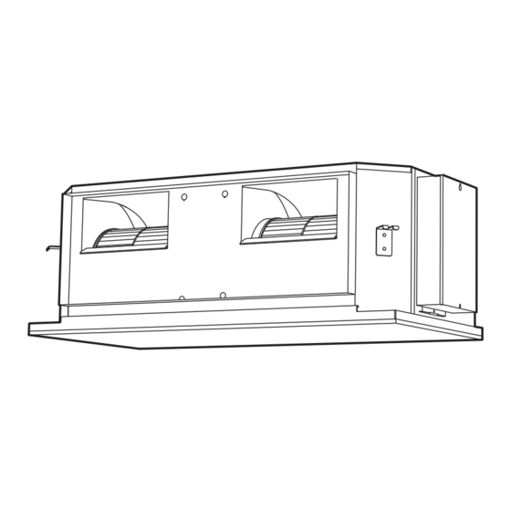
Page 4: Installation Dimension
(1) Install the indoor unit on a place having a suffi cient strength so that it withstands Special nut A (Large) against the weight of the indoor unit. Hanging bolt M10 (Accessories) (2) The inlet and outlet ports should not be obstructed; the air should be able to blow all (locally purchased) over the room. -
Page 5: Pipe Installation
• Use pipe with water-resistant heat insulation. CAUTION To prevent people from touching the parts inside the unit, be sure to install grilles on CAUTION the inlet and outlet ports. The grilles must be designed in such a way that cannot be Install heat insulation around both the gas and liquid pipes. -
Page 6: Installing Heat Insulation
4.3.3. Pipe connection 5. INSTALLING DRAIN PIPES When the fl are nut is tightened properly by your hand, hold the body side coupling with a separate spanner, then tighten with a torque wrench. • Use general hard polyvinyl chloride pipe (VP25) and connect it with adhesive (polyvinyl CAUTION chloride) so that there is no leakage. -
Page 7: Electrical Wiring
Hose opening view 6. ELECTRICAL WIRING Wind the attached heat insulation around the hose band. Make sure the WARNING alignment is on top. Electrical work must be performed in accordance with this Manual by a person certifi ed under the national or regional regulations. Be sure to use a dedicated circuit for the unit. An insuffi... -
Page 8: Electrical Requirement
CAUTION 6.2. Wiring method Earth (Ground) the unit. Example Do not connect the earth (ground) cable to a gas pipe, water pipe, lightning rod, or a telephone earth (ground) cable. Outdoor unit or RB unit *1 Improper earthing (grounding) may cause electric shock. Transmission Do not connect power supply cables to the transmission or remote controller terminals, as this will damage the product. -
Page 9: Connection Of Wiring
WARNING WARNING Tighten the terminal screws to the specifi ed torques, otherwise, abnormal overheating When using solid core cables, do not use the ring terminal. If you use the solid core may be produced and possibly cause heavy damage inside the unit. cables with the ring terminal, the ring terminal’s pressure bonding may malfunction and cause the cables to abnormally heat up. -
Page 10: External Input And External Output (Optional Parts)
When connected to Apply voltage terminals of multiple indoor units with a connected unit, CAUTION be sure to make a branch outside the indoor unit using a pull box, etc. as shown on below When installing a screw on the terminal block, do not cut the cable by overtightening example. - Page 11 ● When function setting is “Operation/Stop” mode. ● When connecting with unit equipped with a power supply [In the case of “Edge” input] P.C.B Connector Input signal Command Connected OFF → ON Operation device 1 Ch1 of CNA01 or CNA02 ON →...
-
Page 12: Remote Sensor (Optional Parts)
6.6. Remote sensor (Optional parts) 6.7. IR receiver unit (Optional parts) • For the installation method, please refer to the INSTALLATION MANUAL of remote • For the installation method, please refer to the INSTALLATION MANUAL of IR receiver sensor. unit. Connection methods Connection methods •... -
Page 13: Custom Code Setting
Setting Setting range Type of switch Rotary switch Example: “0” Setting Remote controller Rotary switch 0 to 15 example address Example: “0” RC AD Example If 4 indoor units are connected. Indoor unit Indoor unit Indoor unit Indoor unit RC AD SW RC AD SW RC AD SW RC AD SW... -
Page 14: Function Setting
7.3. Function setting 8. TEST RUN • FUNCTION SETTING can be performed with the wired or wireless remote controller. 8.1. Test run using Outdoor unit (PCB) (The remote controller is optional equipment) • Refer to the wired or wireless remote controller manual for detailed setting information. •... -
Page 15: Error Codes
Wired remote controller display 10. ERROR CODES UTY-RNKY / UTY-RNKG / UTY-RNKYT (3-wire type) If you use a wired type remote controller, error codes will appear on the remote controller Error code display. If you use a wireless remote controller, the lamp on the photodetector unit will output error codes by way of blinking patterns.
Need help?
Do you have a question about the AirStage ARXC45GATH and is the answer not in the manual?
Questions and answers