
Subscribe to Our Youtube Channel
Related Manuals for Riello RS 810/E FGR


Summary of Contents for Riello RS 810/E FGR
- Page 1 Installation, use and maintenance instructions Forced draught gas burner Modulating operation CODE MODEL TYPE 20160290 RS 810/E FGR S033T1 20163821 (2) - 06/2021...
- Page 2 Translation of the original instructions...
-
Page 3: Table Of Contents
Contents Declarations....................................3 Information and general warnings............................4 Information about the instruction manual ........................4 2.1.1 Introduction.................................. 4 2.1.2 General dangers................................4 2.1.3 Other symbols ................................4 2.1.4 Delivery of the system and the instruction manual...................... 5 Guarantee and responsibility............................5 Safety and prevention................................ - Page 4 Contents Adjustments prior to ignition............................29 Burner start-up ................................30 FGR commissioning..............................31 Air / fuel adjustment ..............................32 6.5.1 Air adjustment for maximum output ...........................32 6.5.2 Air/fuel adjustment and output modulation system ....................32 6.5.3 Burner adjustment..............................32 6.5.4 Output upon ignition ..............................32 6.5.5 Maximum output ................................32 Final adjustment of the pressure switches .........................33 6.6.1 Air pressure switch..............................33...
-
Page 5: Declarations
The quality is guaranteed by a quality and management system certified in accordance with ISO 9001:2015. Manufacturer's Declaration RIELLO S.p.A. declares that the following products comply with the NOx emission limits specified by German standard “1. BIm- SchV revision 26.01.2010”. -
Page 6: Information And General Warnings
Information and general warnings Information and general warnings Information about the instruction manual 2.1.1 Introduction WARNING: MOVING PARTS The instruction manual supplied with the burner: This symbol indicates that you must keep limbs is an integral and essential part of the product and must not away from moving mechanical parts;... -
Page 7: Delivery Of The System And The Instruction Manual
Information and general warnings 2.1.4 Delivery of the system and the instruction The system supplier must carefully inform the user about: – the use of the system; manual – any further tests that may be required before activating the When the system is delivered, it is important that: system;... -
Page 8: Safety And Prevention
Safety and prevention Safety and prevention Introduction The burners have been designed and built in compliance with the type and pressure of the fuel, the voltage and frequency of the current regulations and directives, applying the known technical electrical power supply, the minimum and maximum deliveries for rules of safety and envisaging all the potential danger situations. -
Page 9: Technical Description Of The Burner
3N / 400V / 50Hz 3/230/50 3 / 230V / 50Hz Voltage of auxiliaries: 230/50/60 230V / 50-60Hz 110/50/60 110V / 50-60Hz FS1/FS2 3/400/50 230/50/60 BASIC DESIGNATION EXTENDED DESIGNATION Models available Designation Voltage Start-up Code RS 810/E FGR 3/400/50 Star/Delta 20160290 Tab. A 20163821... -
Page 10: Burner Categories - Countries Of Destination
AT - BG - CH - CZ - DK - EE - ES - FI - FR - GB - GR - HU IE - IS -IT - LT - LV - NO - PT - RO - SE - SI - SK - TR 2E(R) Tab. B Technical data Model RS 810/E FGR Power 1100/3500 ÷ 7000 Output Fuels Natural gas: G20 (methane gas) Gas pressure at max. -
Page 11: Maximum Dimensions
Bear in mind that inspection of the combustion head requires the burner to be opened and the rear part turned on the hinge. The l position is reference for the refractory thickness of the boiler door. 20162917 Fig. 1 RS 810/E FGR 1197 DN80 1222 1345 1055 Tab. -
Page 12: Firing Rates
WARNING shown on page 21. Model RS 810/E FGR 1100 20166064 Fig. 2 NOTE: It is important to be aware that the use of the Flue Gas Recir- culation (FGR) function, in order to achieve an ULTRA Low NOx emission performance, might lower the burner’s maxi-... -
Page 13: Test Boiler
If the burner must be combined with a boiler that has not been EC tion chamber. approved and/or its combustion chamber dimensions are clearly Example: RS 810/E FGR smaller than those indicated in the diagram, consult the manufac- Output 7000 kW - diameter 120 cm - length 6 m. -
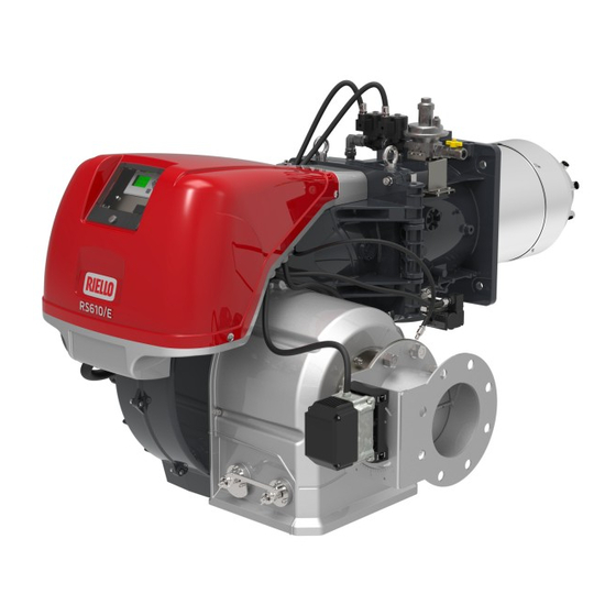
Page 14: Burner Description
Technical description of the burner 4.10 Burner description 20162927 Fig. 4 Lifting rings 30 Gas servomotor Cover for electrical panel 31 Flame sensor Lever for combustion head movement The burner can be opened to the right or to the left Air pressure test point for combustion head without links to the fuel supply side. -
Page 15: Electrical Panel Description
Technical description of the burner 4.11 Electrical panel description 20164316 Fig. 5 Earth terminal Supply cables and external connections passage Main terminal supply board Auxiliary circuits fuse (includes a spare fuse) Air pressure switch Ignition transformer Free contact relay Direct start up line contactor Star/delta start-up line contactor 10 Thermal relay (with reset button) 11 Delta contactor (star/delta start up) -
Page 16: Control Box For The Air/Fuel Ratio (Lmv51.300)
To avoid accidents, material or environmental damage, observe the following instructions! The LMV51... is a safety device! Avoid opening or WARNING modifying it, or forcing its operation. Riello S.p.A. cannot assume any responsibility for damage re- sulting from unauthorised interventions! Risk of explosion! - Page 17 Technical description of the burner Electrical connection of flame detector – Line capacitance reduces the magnitude of the flame signal. – Use a separate cable. It is important for signal transmission to be almost totally free • Respect the allowed cable lengths. of any disturbances or loss: •...
-
Page 18: 4.13 Servomotor
Technical description of the burner 4.13 Servomotor Warnings To avoid accidents, material or environmen- tal damage, observe the following instruc- tions! WARNING Avoid opening, modifying or forcing the ac- tuators. All interventions (assembly and installation operations, assistance, etc.) must be carried out by qualified personnel. ... -
Page 19: 4.14 Calibration Of The Thermal Relay
Technical description of the burner 4.14 Calibration of the thermal relay The thermal relay serves to avoid damage to the motor due to an excessive absorption increase or if a phase is missing. For calibration 2), see the table in the wiring diagram. To reset, in case of an intervention of the thermal relay, press the “RESET”... -
Page 20: Installation
Installation Installation Notes on safety for the installation After carefully cleaning all around the area where the burner will The installation of the burner must be carried out be installed, and arranging the correct lighting of the environ- by qualified personnel, as indicated in this manual ment, proceed with the installation operations. -
Page 21: Operating Position
Installation Operating position The burner is designed to operate only in positions 1, 2, 3 and 4 (Fig. 10). Installation 1 is preferable, as it is the only one that allows the maintenance operations WARNING as described in this manual. ... -
Page 22: Securing The Burner To The Boiler
Installation Securing the burner to the boiler 20162931 Prepare a suitable lifting system using rings 3)(Fig. 13). Fit the heat insulation supplied onto the blast tube 4)(Fig. 13). Fit the entire burner onto the boiler hole prepared previously (Fig. -
Page 23: Combustion Head Adjustment
Installation 5.10 Combustion head adjustment In order to optimise performance, the burner is equipped with a variable geometry combustion head which operates on the basis 20162133 of the delivered output. According to the same rotation of the air servomotor, it is possible to change the combustion head opening by moving the lever 2)(Fig. -
Page 24: Fgr Duct System
Installation 5.11 FGR duct system – Normally the duct would connect to the stack as shown in There must be sufficient condensate drip legs and catch Fig. 18, with a 45° cut facing the flue gas flow and with the space (volume of drip legs) to prevent the condensation from centre of the cut centred in the stack. -
Page 25: 5.11.1 Flue Gas Recirculation Line Sizing
To prepare the Tab. J a flue gas maximum temperature of 260°C was considered. FGR pipe Diameter Length (m) RS 810/E FGR 8” Tab. J To account for the flow resistance at 90° elbows of the flue gas circuit, the following equivalent straight pipe length values can be considered, and shall be deducted from the maximum pipe length values indicated in Tab. -
Page 26: Gas Feeding
Installation 5.12 Gas feeding Explosion danger due to fuel leaks in the pres- MBC “threaded” ence of a flammable source. Precautions: avoid knocking, attrition, sparks and heat. Make sure that the fuel interception tap is closed before performing any operation on the burner. The fuel supply line must be installed by qualified personnel, in compliance with current standards and laws. -
Page 27: 5.12.2 Gas Train
Installation 5.12.2 Gas train Approved according to standard EN 676 and provided separately Beware of train movements: danger of crushing of from the burner. limbs. 5.12.3 Gas train installation Make sure that the gas train is properly installed by checking for any fuel leaks. Disconnect the electrical power using the main system switch. -
Page 28: 5.12.4 Gas Pressure
Find, in the table Tab. L related to the burner concerned, the pressure value closest to the result of the subtraction. – read the corresponding output on the left. Example for RS 810/E FGR with G20 natural gas: Maximum output operation Gas pressure at test point P1)(Fig. 23) 43.7 mbar... -
Page 29: Electrical Wiring
Installation 5.13 Electrical wiring Notes on safety for the electrical wiring The electrical wiring must be carried out with the electrical supply disconnected. Electrical wiring must be made in accordance with the regulations currently in force in the country of destination and by qualified personnel. -
Page 30: Supply Cables And External Connections Passage
Installation 5.13.1 Supply cables and external connections 20164702 passage All the cables to be connected to the burner must be threaded through cable grommets. The use of the cable grommets can take various forms; by way of example see Fig. 24. Key (Fig. -
Page 31: Start-Up, Calibration And Operation Of The Burner
Start-up, calibration and operation of the burner Start-up, calibration and operation of the burner Notes on safety for the first start-up The first start-up of the burner must be carried out Before igniting the burner, see the paragraph by qualified personnel, as indicated in this manual “Safety test - with gas ball valve closed”... -
Page 32: Burner Start-Up
Burner start-up Feed electricity to the burner via the disconnecting switch on the boiler panel. Close the thermostats/pressure switches. Turn the switch to position “AUTO” (Fig. 26). Make sure that the lamps or testers connected to the solenoids, or indicator lights on the solenoids themselves, show that no voltage is present. -
Page 33: Fgr Commissioning
FGR commissioning The flue gas recirculation (FGR) function is used to reduce the First time FGR set up NOx content of flue gases. This is accomplished by feeding a cer- Modify the factory preset: FGR-Mode = time (Auxiliary actuator 3 tain proportion of the flue gas back to the combustion chamber, is held in the ignition position until an adjustable time is reached). -
Page 34: Air / Fuel Adjustment
Air / fuel adjustment 6.5.3 Burner adjustment Air/fuel synchronisation is carried out with the relevant air and gas servomotors by logging a calibration curve by using the elec- The optimum adjustment of the burner requires an analysis of tronic cam. flue gases at the boiler outlet. -
Page 35: Final Adjustment Of The Pressure Switches
In this case also, the pressure gauge must be connected in differ- ential mode, as shown in Fig. 27. On RS 810/E FGR burners the air pressure switch is fitted in an “absolute” mode, that is, connected only to the pressure test point “+”... -
Page 36: Minimum Gas Pressure Switch
Start-up, calibration and operation of the burner 6.6.3 Minimum gas pressure switch Adjust the minimum gas pressure switch (Fig. 29) after perform- ing all the other burner adjustments with the pressure switch set to the start of the scale. With the burner operating at maximum output, increase adjust- ment pressure by slowly turning the relative knob clockwise until the burner stops. -
Page 37: Maintenance
Maintenance Maintenance Notes on safety for the maintenance The periodic maintenance is essential for the good operation, safety, yield and duration of the burner. Disconnect the electrical supply from the burner It allows you to reduce consumption and polluting emissions and by means of the main system switch. -
Page 38: Qri Flame Detector
Maintenance Boiler 7.2.4 QRI flame detector Clean the boiler as indicated in its accompanying instructions in In order to reach the flame detector, proceed as follows: order to maintain all the original combustion characteristics in- extract the QRI flame detector 1)(Fig. 32); tact, especially the flue gas temperature and combustion cham- ... -
Page 39: Checking The Air And Gas Pressure On The Combustion Head
Maintenance 7.2.6 Checking the air and gas pressure on the 7.2.7 Safety components combustion head The safety components should be replaced at the end of their life cycle indicated in the following table. To carry out this operation it is necessary to use a pressure gauge to measure the air and gas pressure at the combustion head, as The specified life cycles do not refer to the warranty terms indi- shown in Fig. -
Page 40: Opening The Burner
Maintenance Opening the burner Disconnect the electrical supply from the burner Wait for the components in contact with heat by means of the main system switch. sources to cool down completely. DANGER To open the burner, use the same procedure set out in “Access to head internal part”... -
Page 41: Faults - Probable Causes - Solutions
Faults - Probable causes - Solutions Faults - Probable causes - Solutions If faults arise in ignition or operations, the burner performs a In the event of a burner lockout, more than two “safety stop”, which is signalled by the red burner lockout LED. consecutive burner reset operations could cause The display visualises alternately the lockout code and the rela- damage to the installation. -
Page 42: Appendix - Accessories
Adjustment field Code PT 100 temperature - 100...+ 500°C 3010110 4 - 20 mA pressure 0...2.5 bar 3010213 RS 810/E FGR 4 - 20 mA pressure 0...16 bar 3010214 Pressione 4 - 20 mA 0...25 bar 3090873 Soundproofing box kit... -
Page 43: B Appendix - Electrical Panel Layout
Appendix - Electrical panel layout Appendix - Electrical panel layout Index of layouts Indication of references Layout of unifilar output Layout of unifilar output Operational layout Operational layout Operational layout Operational layout Electrical connections set by installer Electrical connections set by installer Electrical connections set by installer Indication of references / 1 . - Page 44 Appendix - Electrical panel layout 20163821...
- Page 45 Appendix - Electrical panel layout & & 20163821...
- Page 46 Appendix - Electrical panel layout 20163821...
- Page 47 Appendix - Electrical panel layout 20163821...
- Page 48 Appendix - Electrical panel layout 20163821...
- Page 49 Appendix - Electrical panel layout 20163821...
- Page 50 Appendix - Electrical panel layout 20163821...
- Page 51 Appendix - Electrical panel layout 20163821...
- Page 52 Appendix - Electrical panel layout 20163821...
- Page 53 Appendix - Electrical panel layout 20163821...
- Page 54 Appendix - Electrical panel layout 20163821...
- Page 55 Appendix - Electrical panel layout Wiring layout key Control box Display for control box Probe with output under current Device with output undercurrent, for modifying remote setpoint Load indicator with input under current Device with output under current for remote modulation Pressure probe Pressure probe BT5 FGR Probe Pt1000, 2 wires...
- Page 56 RIELLO S.p.A. I-37045 Legnago (VR) Tel: +39.0442.630111 http:// www.riello.it http:// www.riello.com Subject to modifications...
Need help?
Do you have a question about the RS 810/E FGR and is the answer not in the manual?
Questions and answers