Comfort Glow CGD3924N Owner's Operation And Installation Manual
Yellow flame design unvented (vent-free) natural gas log heater
Hide thumbs
Also See for CGD3924N:
- Owner's operation and installation manual (43 pages) ,
- Owner's operation and installation manual (40 pages) ,
- Owner's operation and installation manual (40 pages)
Table of Contents
Advertisement
Quick Links
UNVENTED (VENT-FREE)
NATURAL GAS LOG HEATER
(Manually-Controlled Models Also Designed Certified as Vented Decorative Appliance)
This appliance may be installed in an aftermarket* manufactured (mobile) home, where
not prohibited by state or local codes. This appliance is only for use with the type of gas
indicated on the rating plate. This appliance is not convertible for use with other gases.
* Aftermarket: Completion of sale, not for purpose of resale, from the manufacturer
OWNER'S OPERATION AND INSTALLATION MANUAL
18", 24", and
30" Variable
Manually-
Controlled
Models
CGD3018N
CGD3924N
CGD3930N
WARNING: If the information in this
manual is not followed exactly, a fire or
explosion may result causing property
damage, personal injury, or loss of life.
— Do not store or use gasoline or other
flammable vapors and liquids in the
vicinity of this or any other appliance.
— WHAT TO DO IF YOU SMELL GAS
• Do not try to light any appliance.
• Do not touch any electrical switch;
do not use any phone in your build-
ing.
• Immediately call your gas supplier
from a neighbor's phone. Follow the
gas supplier's instructions.
• If you cannot reach your gas sup-
plier, call the fire department.
— Installation and service must be per-
formed by a qualified installer, service
agency, or the gas supplier.
YELLOW FLAME DESIGN
Save this manual for future reference.
Thermostatically-
Controlled Models
WARNING: Improper installation, adjust-
ment, alteration, service, or maintenance
can cause injury or property damage.
Refer to this manual for correct installa-
tion and operational procedures. For as-
sistance or additional information con-
sult a qualified installer, service agency,
or the gas supplier.
WARNING: This gas log set is for installa-
tion in a masonry solid fuel burning fire-
place, a U.L. listed manufactured solid fuel
burning fireplace or an AGA design certi-
fied vent-free firebox listed for use with
these gas log models (Including CGFB32C
and CGFB32NC series).
WARNING: This is an unvented gas-fired
heater. It uses air (oxygen) from the room
in which it is installed. Provisions for ad-
equate combustion and ventilation air must
be provided. Refer to Air for Combustion
and Ventilation section in this manual.
24" and 30"
CGD3924NT
CGD3930NT
®
Patent Pending
Advertisement
Table of Contents

Subscribe to Our Youtube Channel
Related Manuals for Comfort Glow CGD3924N


Summary of Contents for Comfort Glow CGD3924N
- Page 1 30" Variable Controlled Models Manually- Controlled CGD3924NT Models CGD3930NT CGD3018N CGD3924N CGD3930N ® Patent Pending WARNING: Improper installation, adjust- WARNING: If the information in this ment, alteration, service, or maintenance manual is not followed exactly, a fire or can cause injury or property damage.
-
Page 2: Table Of Contents
CONTENTS SECTION PAGE Safety Information ................... 2 Product Identification ................4 Local Codes ..................... 4 Unpacking ....................4 Product Features ..................4 Air for Combustion and Ventilation ............5 Installing ....................8 Check Gas Type ................8 Installation and Clearances (Vent-Free Operation Only) ....9 Installing Damper Clamp Accessory for Vented Operation .... - Page 3 WARNINGS Continued SAFETY WARNING: Any change to this heater or its controls can be dangerous. 1. This appliance is only for use with the type of gas indicated on the rating plate. This INFORMATION appliance is not convertible for use with other gases. 2.
-
Page 4: Product Identification
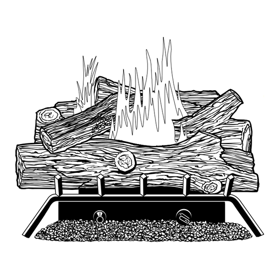
PRODUCT Crossover Log Back Log IDENTIFICATION Front Log Burner Middle Log Piezo Ignitor Control Knob Base Grate Figure 1 - Vent-Free Gas Log Heater LOCAL CODES Install and use heater with care. Follow all local codes. In the absence of local codes, use the latest edition of The National Fuel Gas Code ANSI Z223, also known as NFPA 54*. -
Page 5: Air For Combustion And Ventilation
AIR FOR WARNING COMBUSTION This heater shall not be installed in a confined space unless provisions are provided for adequate combustion and ventilation air. Read the following instructions to insure proper fresh air for VENTILATION this and other fuel-burning appliances in your home. Today’s homes are built more energy efficient than ever. - Page 6 AIR FOR DETERMINING AIR FLOW FOR HEATER LOCATION Determining if You Have a Confined or Unconfined Space COMBUSTION Use this work sheet to determine if you have a confined or unconfined space. Space: Includes the room in which you will install heater plus any adjoining rooms with VENTILATION doorless passageways or ventilation grills between the rooms.
- Page 7 AIR FOR WARNING COMBUSTION If the area in which the heater may be operated is smaller than that defined as an unconfined space, provide adequate combus- tion and ventilation air by one of the methods described in the VENTILATION National Fuel Gas Code, ANSI Z223.1, 1992, Section 5.3 or applicable local codes.
-
Page 8: Installing
INSTALLING NOTICE A qualified service person must install heater. Follow all local codes. NOTICE State or local codes may only allow operation of this appliance in a vented configuration. Check your state or local codes. WARNING Before installing in a solid fuel burning fireplace, the chimney flue and firebox must be cleaned of soot, creosote, ashes and loose paint by a qualified chimney cleaner. -
Page 9: Installation And Clearances (Vent-Free Operation Only)
INSTALLING INSTALLATION AND CLEARANCES (Vent-Free Operation Only) Continued WARNING Maintain the minimum clearances. If you can, provide greater clear- ances from floor, ceiling, and adjoining wall. MINIMUM FIREPLACE CLEARANCE TO COMBUSTIBLE MATERIALS Log Size Side Wall Ceiling 18", 24", 30" 16"... - Page 10 INSTALLING NOTICE You may use this heater as a vented product. If so, you must Continued always run heater with chimney flue damper open. If running heater with damper open, non-combustible material above fire- place opening is not needed. Go to Installing Damper Clamp Accessory for Vented Operation, page 13.
- Page 11 Minimum Non-Combustible Material Clearances INSTALLING If Using Mantel Continued You must have non-combustible material(s) above the fireplace opening. Non- combustible materials (such as slate, marble, tile, etc.) must be at least 1/2 inch thick. With sheet metal, you must have non-combustible material behind it. Non- combustible material must extend at least 8 inches up (for all models).
- Page 12 INSTALLING Determining Minimum Mantel Clearance When Using a Hood If minimum clearances in Figure 6 are not met, you must have a hood. When Continued using a hood there are still certain minimum mantel clearances required. Follow minimum clearances shown in Figure 7 when using hood. Mantel Shelf 12"...
-
Page 13: Installing Damper Clamp Accessory For Vented Operation
INSTALLING INSTALLING DAMPER CLAMP ACCESSORY FOR VENTED OPERATION Continued Note: When used as a vented heater, appliance must be installed only in a solid- fuel burning fireplace with a working flue and constructed of non-combustible material. If your heater is a manually controlled model, you may use this heater as a vented product. -
Page 14: Installing Heater Base Assembly
INSTALLING HEATER BASE ASSEMBLY INSTALLING WARNING Continued You must secure this heater to fireplace floor. If not, heater will move when you adjust controls. Moving heater may cause a gas leak. WARNING If installing in a sunken fireplace, special care is needed. You must raise the fireplace floor to allow access to heater control panel. - Page 15 INSTALLING Heater Gas Continued Regulator Fitting Flexible Gas Hose (if allowed by local codes) Figure 11 - Attaching Flexible Gas Hose to Heater Gas Regulator Masonry Screw Mounting Bracket Figure 12 - Attaching Base Assembly to Fireplace Floor 103603...
-
Page 16: Connecting To Gas Supply
INSTALLING CONNECTING TO GAS SUPPLY Continued NOTICE A qualified service person must connect heater to gas supply. Follow all local codes. Installation Items Needed Before installing heater, make sure you have the items listed below. • piping (check local codes) •... -
Page 17: Checking Gas Connections
INSTALLING CAUTION Continued Avoid damage to regulator. Hold gas regulator with wrench when connecting it to gas piping and/or fittings. A.G.A. Design-Certified Manual Shutoff Valve From With 1/8" NPT Tap* Approved Flexible Gas Meter Gas Hose (if allowed (5" W.C.** to by local codes) 10.5"... - Page 18 INSTALLING 3. Pressurize supply piping system by either using compressed air or opening main gas valve located on or near gas meter. Continued 4. Check all joints of gas supply piping system. Apply mixture of liquid soap and water to gas joints. Bubbles forming show a leak. 5.
-
Page 19: Installing Logs
INSTALLING INSTALLING LOGS Continued WARNING Failure to position the parts in accordance with these diagrams or failure to use only parts specifically approved with this heater may result in property damage or personal injury. Each log is marked with a number. These numbers will help you identify the log when installing. -
Page 20: Operating Heater (Manually-Controlled Models)
OPERATING FOR YOUR SAFETY READ BEFORE LIGHTING HEATER WARNING Manually- If you do not follow these instructions exactly, a fire or explosion may Controlled Models result causing property damage, personal injury or loss of life. A. This appliance has a pilot which must be lighted by hand. When lighting the pilot, follow these instructions exactly. - Page 21 OPERATING 5. Slightly depress and turn control knob counterclockwise to the PILOT C-clockwise position. Press in control knob for five (5) seconds (see Page 20). HEATER Note: You may be running this heater for the first time after hooking up to gas supply.
-
Page 22: Operating Heater (Thermostatically-Controlled Models)
OPERATING MANUAL LIGHTING PROCEDURE HEATER 1. Follow steps 1 through 5 under Lighting Instructions, pages 20 and 21. 2. Depress control knob and light pilot with match. Manually- 3. Keep control knob pressed in for 30 seconds after lighting pilot. After 30 seconds, release control knob. - Page 23 OPERATING 1. STOP! Read the safety information above. 2. Make sure manual shutoff valve is fully open. HEATER 3. Turn control knob clockwise to the OFF position. Clockwise Thermostatically- Controlled Models Continued Control Knob Ignitor Button Figure 22 - Control Knob and Ignitor Button Location 4.
-
Page 24: Inspecting Burners
OPERATING TO TURN OFF GAS TO APPLIANCE HEATER Shutting Off Heater 1. Turn control knob clockwise to the OFF position. Thermostatically- Clockwise Shutting Off Burners Only (pilot stays lit) Controlled Models 1. Turn control knob clockwise to the PILOT position. Clockwise Continued THERMOSTAT CONTROL OPERATION... -
Page 25: Cleaning And Maintenance
CLEANING WARNING Turn off heater and let cool before cleaning. MAINTENANCE CAUTION You must keep control areas, burner, and circulating air passage- ways of heater clean. Inspect these areas of heater before each use. Have heater inspected yearly by a qualified service person. Heater may need more frequent cleaning due to excessive lint from carpeting, bedding material, etc. - Page 26 OBSERVED POSSIBLE TROUBLE- PROBLEM CAUSE REMEDY SHOOTING When ignitor button 1. Gas supply turned off or 1. Turn on gas supply or Continued is pressed, there is manual shutoff valve open manual shutoff spark at ODS/pilot closed valve but no ignition 2.
- Page 27 OBSERVED POSSIBLE TROUBLE- PROBLEM CAUSE REMEDY SHOOTING Burner does light 1. Burner orifice clogged 1. Clean burner (see Continued after ODS/pilot is lit Cleaning and Mainte- nance, page 25) or replace burner orifice 2. Inlet gas pressure is 2. Contact local natural gas too low company 3.
- Page 28 TROUBLE- WARNING SHOOTING If you smell gas • Shut off gas supply. Continued • Do not try to light any appliance. • Do not touch any electrical switch; do not use any phone in your building. • Immediately call your gas supplier from a neighbor’s phone. Follow the gas supplier’s instructions.
-
Page 29: Optional Positioning Of Thermostat Sensing Bulb
If your log set cycles to pilot, but the room temperature drops to a lower OPTIONAL than ideal comfort level before the log set comes back on, you may want to POSITIONING reposition the thermostat sensing bulb. The thermostat sensing bulb is located near the gas valve assembly on the mounting bracket. - Page 30 Thermostat OPTIONAL Sensing Bulb POSITIONING Adhesive-backed Mounting Clip THERMOSTAT SENSING BULB Figure 29 - Locating Thermostat Sensing Bulb on Masonry Fireplace For Masonry and Factory-built If you have a factory-built metal fireplace, see Figure 30 for location. Metal Fireplace Thermostat Continued Sensing Bulb Adhesive-backed...
-
Page 31: Technical Service
TECHNICAL You may have further questions about installation, operation, or troubleshooting. If so, contact DESA International’s Technical Service Department at SERVICE 1-800-DESA LOG (1-800-337-2564). SPECIFICATIONS 18" Model 24" Models 30" Models Btu (Variable) 16,000/30,000 20,000/39,000 20,000/39,0000 Type Gas Natural Gas Only Natural Gas Only Natural Gas Only Ignition... -
Page 32: Replacement Parts
Note: Use only original replacement parts. This will protect your warranty cover- REPLACEMENT age for parts replaced under warranty. PARTS Parts Under Warranty Contact authorized dealers of this product. If they can’t supply original replace- ment part(s), call DESA International’s Technical Service Department at 1-800-DESA LOG (1-800-337-2564). -
Page 33: Accessories
Purchase these fireplace accessories from your local dealer. If they can not supply ACCESSORIES these accessories, call DESA International’s Sales Department at 1-800-972-7879 for referral information. You can also write to the address listed on the back page of this manual. MANUAL SHUTOFF VALVE - GA5010 For all models. -
Page 34: Illustrated Parts Lists
ILLUSTRATED PARTS BREAKDOWN Variable Manually- Controlled Models CGD3018N CGD3924N CGD3930N 20-2 20-1 103603... - Page 35 This list contains replaceable parts used in your heater. When ordering parts, PARTS LIST follow the instructions listed under Replacement Parts on page 32 of this manual. CGD3018N CGD3924N CGD3930N PART NUMBER PART NUMBER PART NUMBER DESCRIPTION QTY. 103008-02 103008-01...
- Page 36 ILLUSTRATED PARTS BREAKDOWN Thermostatically- Controlled Models CGD3924NT CGD3930NT 20-2 20-1 103603...
- Page 37 This list contains replaceable parts used in your heater. When ordering parts, PARTS LIST follow the instructions listed under Replacement Parts on page 32 of this manual. CGD3924NT CGD3930NT PART NUMBER PART NUMBER DESCRIPTION QTY. 103008-01 103008-03 Back Log (#1) 103009-01 103009-03 Middle Log (#2)
- Page 38 NOTES ________________________________________________________________ ________________________________________________________________ ________________________________________________________________ ________________________________________________________________ ________________________________________________________________ ________________________________________________________________ ________________________________________________________________ ________________________________________________________________ ________________________________________________________________ ________________________________________________________________ ________________________________________________________________ ________________________________________________________________ ________________________________________________________________ ________________________________________________________________ ________________________________________________________________ ________________________________________________________________ ________________________________________________________________ ________________________________________________________________ ________________________________________________________________ ________________________________________________________________ ________________________________________________________________ ________________________________________________________________ ________________________________________________________________ ________________________________________________________________ ________________________________________________________________ ________________________________________________________________ ________________________________________________________________ ________________________________________________________________ ________________________________________________________________ ________________________________________________________________ ________________________________________________________________ ________________________________________________________________ ________________________________________________________________ ________________________________________________________________ ________________________________________________________________ ________________________________________________________________ ________________________________________________________________ ________________________________________________________________ ________________________________________________________________ 103603...
- Page 39 NOTES ________________________________________________________________ ________________________________________________________________ ________________________________________________________________ ________________________________________________________________ ________________________________________________________________ ________________________________________________________________ ________________________________________________________________ ________________________________________________________________ ________________________________________________________________ ________________________________________________________________ ________________________________________________________________ ________________________________________________________________ ________________________________________________________________ ________________________________________________________________ ________________________________________________________________ ________________________________________________________________ ________________________________________________________________ ________________________________________________________________ ________________________________________________________________ ________________________________________________________________ ________________________________________________________________ ________________________________________________________________ ________________________________________________________________ ________________________________________________________________ ________________________________________________________________ ________________________________________________________________ ________________________________________________________________ ________________________________________________________________ ________________________________________________________________ ________________________________________________________________ ________________________________________________________________ ________________________________________________________________ ________________________________________________________________ ________________________________________________________________ ________________________________________________________________ ________________________________________________________________ ________________________________________________________________ ________________________________________________________________ ________________________________________________________________ 103603...
-
Page 40: Warranty Information
We make no other warranty, expressed or implied. LIMITED WARRANTY COMFORT GLOW VENT-FREE NATURAL GAS LOG HEATERS DESA International warrants this product to be free from defects in materials and components for two (2) years from the date of first purchase, provided that the product has been properly installed, operated and maintained in accordance with all applicable instructions.
Need help?
Do you have a question about the CGD3924N and is the answer not in the manual?
Questions and answers