
Related Manuals for SIMAG SP 125


Summary of Contents for SIMAG SP 125
- Page 1 SERVICE MANUAL SPN 405 SPN 605 SPN 1205 R134A - R404A Electronic Modular Flakers and Superflakers...
-
Page 2: Table Of Contents
Page 1 Table of contents page TABLE OF Specifications SP 125 CONTENTS Specifications SP 255 Specifications SPN 405 Specifications SPN 605 Specifications SPN 1205 GENERAL INFORMATION AND INSTALLATION Introduction Unpacking and Inspection - Ice maker Unpacking and Inspection - Storage bin... - Page 3 Page 2 SPECIFICATIONS ELECTRONIC MODULAR FLAKER MODEL SP 125 Important operating requirements: • Air temperature 10°C (50°F) 40°C (100°F) • Water temperature 5°C (40°F) 35°C (90°F) • Water pressure 1 bar (14 psi) 5 bars (70 psi) • Electr. voltage •...
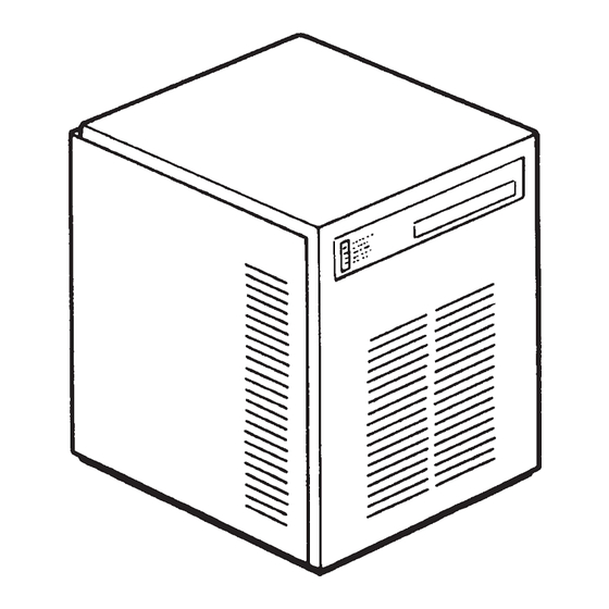
- Page 4 HEIGHT (less legs) 525 mm. HEIGHT (with legs) 542 mm. WIDTH 560 mm. DEPTH 533 mm. WEIGHT 49 Kg. SP 125 - MACHINE SPECIFICATIONS Water req. Model Cond. unit Comp. HP Finish lt/24 HR SP 125 AS 120* S. Steel...
- Page 5 Page 4 SPECIFICATIONS ELECTRONIC MODULAR FLAKER MODEL SP 255 Important operating requirements: • Air temperature 10°C (50°F) 40°C (100°F) • Water temperature 5°C (40°F) 35°C (90°F) • Water pressure 1 bar (14 psi) 5 bars (70 psi) • Electr. voltage •...
- Page 6 Page 5 SPECIFICATIONS Dimensions: HEIGHT (less legs) 525 mm. HEIGHT (with legs) 542 mm. WIDTH 533 mm. DEPTH 533 mm. WEIGHT 49 Kg. SP 255 - MACHINE SPECIFICATIONS Water req. Model Cond. unit Comp. HP Finish lt/24 HR SP 255 AS 200* S.
- Page 7 Page 6 SPECIFICATIONS ELECTRONIC MODULAR SUPERFLAKER MODEL SPN 405 Important operating requirements: • Air temperature 10°C (50°F) 40°C (100°F) • Water temperature 5°C (40°F) 35°C (90°F) • Water pressure 1 bar (14 psi) 5 bars (70 psi) • Electr. voltage •...
- Page 8 Page 7 SPECIFICATIONS Dimensions: HEIGHT (less legs) 645 mm. HEIGHT (with legs) 650 mm. WIDTH 538 mm. DEPTH 663 mm. WEIGHT 77 Kg. SPN 405 - MACHINE SPECIFICATIONS Water req. Model Cond. unit Finish Comp. HP lt/24 HR SPN 405 AS 320* S.
- Page 9 Page 8 SPECIFICATIONS ELECTRONIC MODULAR SUPERFLAKER MODEL SPN 605 Important operating requirements: • Air temperature 10°C (50°F) 40°C (100°F) • Water temperature 5°C (40°F) 35°C (90°F) • Water pressure 1 bar (14 psi) 5 bars (70 psi) • Electr. voltage •...
- Page 10 Page 9 SPECIFICATIONS Dimensions: HEIGHT (less legs) 785 mm. HEIGHT (with legs) 790 mm. WIDTH 538 mm. DEPTH 663 mm. WEIGHT 93 Kg. SPN 605 - MACHINE SPECIFICATIONS Water req. Model Cond. unit Finish Comp. HP lt/24 HR SPN 605 AS 600* S.
- Page 11 Page 10 SPECIFICATIONS ELECTRONIC MODULAR SUPERFLAKER MODEL SPN 1205 Important operating requirements: • Air temperature 10°C (50°F) 40°C (100°F) • Water temperature 5°C (40°F) 35°C (90°F) • Water pressure 1 bar (14 psi) 5 bars (70 psi) • Electr. voltage •...
- Page 12 Page 11 SPECIFICATIONS Dimensions: HEIGHT 850 mm. WIDTH 1065 mm. DEPTH 698 mm. WEIGHT 179 Kg. SPN 1205 - MACHINE SPECIFICATIONS Water req. Model Cond. unit Comp. HP Finish lt/24 HR SPN 1205 AS 1150* S. Steel SPN 1205 WS Water 8000* Basic electr.
-
Page 13: General Information And Installation
Page 12 GENERAL INFORMATION AND INSTALLATION INTRODUCTION On models SP 125, SP 255, SPN 405- 605 remove the front/top panel while on model SPN 1205 remove top and sides panels of the unit This manual provides the specifications and the and inspect for any concealed damage. -
Page 14: Location And Levelling
NOTE. Bin wall gasket must be cut to clear following limitations will constitute the stiffener ends as shown on drawing. misuse under the terms of the SIMAG Do not put any stiffeners crossing the ice Manufacturer’s Limited Warranty resulting drop opening. -
Page 15: Electrical Connections
Remove the tape and fasten the catch using the two self-tapping screws supplied. WATER SUPPLY - WATER COOLED MODELS The water cooled versions of SIMAG Ice Makers require two separate inlet water supplies, ELECTRICAL CONNECTIONS one for the water making the flaker ice and the other for the water cooled condenser. -
Page 16: Installation Practice
12. Has the owner been given the name and Check all refrigerant lines and conduit lines the phone number of the authorized SIMAG to guard against vibrations and possible failure. Service Agency serving him? G. INSTALLATION PRACTICE 1. -
Page 17: Operating Instructions
Page 16 OPERATING INSTRUCTIONS Elapsed the 3 minutes - stand by period - START UP the unit starts operating with the activation in sequence of the following assemblies: After having correctly installed the ice maker and completed the plumbing and electrical GEAR MOTOR/S connections, perform the following “Start-up”... - Page 18 Page 17 FIG. 2 WATER LEVEL RESET GEAR MOTOR ROTATION CONTACTOR COIL RELAYS CONDENSER TEMP. T 40÷50°C EVAPORATOR TEMP. GEAR MOTOR ICE LEVEL CONTROL TRIAC FAN MOTOR TRANSF. ELECTRONIC CARD FIG. 3 WATER LEVEL RESET GEAR MOTOR ROTATION CONTACTOR COIL RELAYS CONDENSER TEMP.
-
Page 19: Operational Checks
Page 18 NOTE. On air cooled models, the condenser NOTE. If, after ten minutes from the compressor start-up, the evaporating tem- temperature sensor, which is located within perature has not dropped down to a value the condenser fins, keeps the head °... - Page 20 Page 19 Opening the water supply line shutoff valve to fill This will cause a gradual decrease of the water up again the float reservoir, the YELLOW LED level in the float reservoir and as soon as the goes off while the RED LED starts blinking. level gets below the two vertical metal pins, the After 3 minutes the unit resumes its total operation flaker stops to operate and the YELLOW warning...
- Page 21 Page 20 If previously installed, remove the refrigerant NOTE. The ICE LEVEL CONTROL service gauges and re-fit the unit service panels (INFRARED SYSTEM) is independent of the previously removed. temperature however, the reliability of its detection can be affected by external light radiations or by any sort of dirt and scale Instruct the owner/user on the general sediment which may deposit directly on the...
-
Page 22: Principle Of Operation (How It Works)
Page 21 PRINCIPLE OF OPERATION WATER CIRCUIT SP 125-255 ICE SPOUT The water enter in the machine through the water inlet fitting which incorporates a strainer - FLOAT TANK located at the rear side of the cabinet - then it... -
Page 23: Refrigerant Circuit
SPN1205), the unit stops after six seconds, 8.5 bar (120 psig) on SP 125 and of 17 bar with the simulteneous glowing of the YELLOW (240 psig) on SP255, SPN405-605 and SPN 1205 LED signalling the “Full Bin”... - Page 24 Page 23 tube connected to the liquid refrigerant line. As The RED LED starts blinking and three pressure increases, the water regulating valve minutes later the flaker unit resume its normal opens to increase the flow of cooling water to the operating mode.
-
Page 25: Mechanical System
Page 24 MECHANICAL SYSTEM RE-SET push button or switch OFF and ON the power line main disconnnect switch The mechanical system of the SIMAG Flaker (Fig. 7). machines consists basically of a gear motor assembly (two on model SPN1205) which drives,... -
Page 26: Operating Pressures
NOTE. Before charging the refrigerant system Air cooled Water cooled always check the type of refrigerant and quantity as specified on the individual ice machine SP 125 440 gr 400 gr dataplate. The refrigerant charges indicated are relatives to averages operating conditions. -
Page 27: Components Description
Page 26 COMPONENTS DESCRIPTION In the event the condenser temperature rises ° ° and reaches 60 C or 70 C according to the EVAPORATOR TEMPERATURE setting of DIP SWITCH number 8 the current SENSOR arriving to the micro processor is such to cause an immediate and total stop of the machine operation. - Page 28 Page 27 As soon as the ice is scooped out (with the YELLOW LED resumption of the light beam between the two Unit shut-off due to a infrared sensor of ice level control) 6 seconds later the too lo-water level into ice machine resumes its operation with the simul- float tank taneous extinguishing the 2nd YELLOW LED.
- Page 29 Page 28 the cooling coil with the evaporating chamber G. JUMPERS and in its interior is located the auger which The Flaker PC Board is equipped by three jumpers: rotates on its vertical axis and it is maintained J1 · TEST: Used in the factory to energise all aligned by the top and bottom bearings.
- Page 30 Page 29 FAN MOTOR (Air cooled version) As pressure increases, the water regulating valve opens to increase the flow of cooling The fan motor is controlled through the TRIAC of water. the P.C. BOARD by the condenser temperature sensor. Normally it operates to draw cooling air through the condenser fins.
-
Page 31: Adjustment, Removal And Replacement Procedures
ICE LEVEL CONTROL mounting bracket of the water reservoir to the unit cabinet and raise the water reservoir to the On SP 125, SP 255, SPN405 and SPN605 correct level. remove the front/top panel, while on SPN 1205 remove the front and rear panels. -
Page 32: Replacement Of P.c. Board
MAGNETIC SENSOR spout. On SP 125, SP 255, SPN405 -605 remove On the model SP125-255 unthread the S.S. the front/top and side/rear panels and on SPN 1205 spout from the brass casting while on the other remove the front, top and left side panels. -
Page 33: Replacement Of The Gear Motor Assy
Page 32 Clean away the old grease from the interior 16. Install the upper bearing into the ice breaker of the ice breaker and inspect the bearing pressed starting by the radial portion that must be fitted into the top of the ice breaker and if worn do not with the flat surface facing up. -
Page 34: Replacement Of Drier
Page 33 On the models SP125-255, SPN405-605 Unsolder and disconnect the capillary tube remove the bolts securing the fan motor bracket and the accumulator/suction line assy from the to the cabinet base and then remove the outlet line of the freezing cylinder. assembly. -
Page 35: Replacement Of Water Cooled Condenser
Page 34 REPLACEMENT OF WATER COOLED NOTE. It is imperative to install a replacement CONDENSER drier whenever the sealed refrigeration system is open. Do not replace the drier until Remove front/top and side/rear panels on all other repairs or replacements have been models SP125-255, SPN405-605 and the front completed. -
Page 36: Wiring Diagram
Page 35 WIRING DIAGRAM SP 125-255 AIR AND WATER COOLED 230/50/1 GV - YELLOW GREEN B - WHITE G - GREY N - BLACK A - BLUE M - BROWN V - GREEN... - Page 37 Page 36 WIRING DIAGRAM SPN 405 -SPN 605 AIR AND WATER COOLED SINGLE PHASE GV - YELLOW GREEN B - WHITE G - GREY N - BLACK A - BLUE M - BROWN V - GREEN...
- Page 38 Page 37 WIRING DIAGRAM SPN 605 AIR AND WATER COOLED GV - YELLOW GREEN THREE PHASE B - WHITE G - GREY N - BLACK A - BLUE M - BROWN V - GREEN...
- Page 39 Page 38 WIRING DIAGRAM SPN 1205 AIR AND WATER COOLED GV - YELLOW GREEN B - WHITE THREE PHASE G - GREY N - BLACK A - BLUE M - BROWN V - GREEN...
-
Page 40: Service Diagnosis
Page 39 SERVICE DIAGNOSIS SYMPTON POSSIBLE CAUSE SUGGESTED CORRECTION Unit will not run Blown fuse in P.C.Board Replace fuse & check for cause of No LED lighted-on blown fuse Master switch in OFF position Turn switch to ON position Inoperative P.C.Board Replace P.C.Board Loose electrical connections Check wiring... - Page 41 Page 40 SERVICE DIAGNOSIS SYMPTON POSSIBLE CAUSE SUGGESTED CORRECTION Wet ice Ambient temperature too high Move unit to cooler location Under or overcharge of refrigerant Recharge with correct quantity High water level in the freezer Lower to approx. 20 mm below ice spout Faulty compressor Replace...
-
Page 42: Maintenance And Cleaning Instructions
SIMAG Cleaner plain. With the ice machine and fan motor OFF on air cooled models, clean condenser using vacuum... - Page 43 (45°-50°C) with a 0,2-0,3 liters of 12. Stop the icemaker and pour warm water on SIMAG Ice Machine Cleaner (on SPN 1205 the ice deposited into the storage bin to melt it up. double the quantities).
- Page 44 SIMAG Singapore Office via Risorgimento, 4 SIMAG FAR EAST 20017 Mazzo di Rho (MI) - Italy 627A Aljunied Road Tel. +39 02 93900215 (Commerciale - Sales Dept.) 04-04 Biztech Centre Tel. +39 02 93960357 (Assistenza - Service Dept.) Singapore 389842 Fax +39 02 93900226 (Commerciale - Sales Dept.)
Need help?
Do you have a question about the SP 125 and is the answer not in the manual?
Questions and answers