
Related Manuals for Golden Technologies Buzzaround Extreme GB118EX


Summary of Contents for Golden Technologies Buzzaround Extreme GB118EX
- Page 1 Buzzaround Extreme Service Guide GB118EX GB148EX This Service Guide contains: Troubleshooting Replacement Instructions Multi-meter Instructions ...
- Page 2 2 ...
-
Page 3: Table Of Contents
Table of Contents Nomenclature and Contact Information......................4 ABOUT THE BUZZAROUND EXTREME SERVICE GUIDE..............5 Buzzaround Extreme Components......................5-10 Wiring Diagram............................11-12 SCENARIO 1: Turn the key to the on position and no power..............13 SCENARIO 2: Batteries will not charge......................14 BEEP/FLASH CODES...........................15-20 BEEP/FLASH CODE #1 – Batteries Low (Scooter may drive slowly)............15 BEEP/FLASH CODE #2 –... -
Page 4: Nomenclature And Contact Information
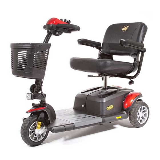
16 18 20 6 10 7 9 Figure 1. Buzzaround Extreme (Model GB118EX) Contact Information Toll-free: 800-624-6374 Golden Technologies Mobility Tech: x501 401 Bridge Street Lift Chair: x502 Old Forge, PA 18518 VA Tech: x505 Fax: 800-628-5165 Email: parts@goldentech.com 4 ... -
Page 5: About The Buzzaround Extreme Service Guide
This service guide provides you with the information necessary to troubleshoot the Golden Technologies Buzzaround Extreme GB118EX/GB148EX. The troubleshooting scenarios in this manual consist of procedures that enable you to systematically trace and correct faults in the system. Appendices A and B include instructions on how to measure voltage and continuity with a multimeter. - Page 6 Component: Circuit Breaker - #1 Location: Mounted on the right-side battery pack. See figure 2. Function: Protects battery circuit from current overload. When the current draw exceeds the breaker rating, the circuit breaker will open. Connections: The circuit breaker is connected to the positive (+) terminal on one battery and the negative (-) terminal on the other.
- Page 7 1 2 Main Harness Figure 5. Controller Component: Power Harness - #5 Location: Mounted to the front frame – located under the battery packs. See #5, figure 4 on page 6. Function: Connects the Battery packs to the controller. Connections: Connects the battery packs to the controller (Bat -) and (Bat +) connections.
- Page 8 Component: Front Intermediate Harness - #8 Location: Mounted on the front frame. See figure 6. Function: Provides connectivity between the motor/brake and the controller. Connections: Connected to the rear intermediate connector (9) and the controller (6). Refer to the wiring diagram on page 11. Failure Signs: Scooter will run slowly or not at all.
- Page 9 Component: Speed Pot (Potentiometer) - #12 Location: Mounted on the control panel. See #1 on figure 9. Function: The speed pot uses variable resistance to control the speed of the scooter. Connections: Connected to the main harness through the control panel harness.
- Page 10 Component: Off-Board Charger (Not shown) Location: Stored inside a pouch on the seatback. Function: Recharges batteries. Connections: Connects to the charger port on the tiller. Refer to the wiring diagram on page 11. Failure Signs: Charger power LED does not go on. Batteries will not charge.
-
Page 11: Wiring Diagram
Note: Blinking red LED is the diagnostic flash code indicator. (Purple wire) Throttle Pot (14) Horn Switch Fuse 1A Speed Pot (12) Fuse 10A 40 AMP Circuit Breaker (1) Dynamic R-Series Controller (6) Fuse 100A Battery Harnesses (4) Power Harness (5) Main Harness (7) Rear Intermediate Connector (9) Front Intermediate Harness (8) - Page 12 Figure 11a. Buzzaround Extreme Wiring Diagram 12 ...
-
Page 13: Scenario 1: Turn The Key To The On Position And No Power
SCENARIO 1: TURN THE KEY TO THE ON POSITION AND NO POWER Put the key into the key switch and turn to the on position. There is no power to the control panel. The horn does not work and the battery condition meter does not work. Battery voltage travels from the batteries, through the controller and the key switch. -
Page 14: Scenario 2: Batteries Will Not Charge
SCENARIO 2: BATTERIES WILL NOT CHARGE Most battery chargers need to “see” at least 16VDC at the charger port. Otherwise, they may not send a charging current to the batteries. This test will ensure that the battery voltage is making it to the charger port. You will need to check battery voltage and wiring harness continuity inside the battery packs. -
Page 15: Beep/Flash Codes
BEEP/FLASH CODES The controller uses audible beeps/flashes to indicate the status of the system. When the controller notices that there is a malfunction in the system, it will beep/flash a code when the power is on. For example, when it beeps/flashes five times and stops that indicates beep/flash code #5 –... -
Page 16: Beep/Flash Code #5 - Brake Fault
Check for Continuity on the Front Intermediate Harness. 5. Remove the two gray floor panels by pushing them up from the underside of the scooter frame. 6. Remove the four screws fastening the floor shroud. 7. Disconnect the front intermediate harness (8) from the controller. Refer to the wiring diagram on page 11. 8. -
Page 17: Beep/Flash Code #6 - Paddle Fault (Out Of Neutral)
Check for Continuity on the Front Intermediate Harness. 10. Separate the front and rear halves of the scooter. 11. Measure resistance from the connector (J3) pin 1 an pin 2 to the two middle pins on the connector of the front intermediate harness (8). -
Page 18: Beep/Flash Code #7 - Paddle Fault/Speed Control Fault (Voltage Error)
BEEP/FLASH CODE #7 - THROTTLE POT/SPEED CONTROL FAULT This Beep/Flash Code occurs because there is a fault with the throttle pot, speed pot, or the associated wiring. Check Throttle Pot Resistance at Controller. 1. Remove the seat. 2. Remove the battery packs. 3. -
Page 19: Beep/Flash Code #8 - Motor Voltage Fault (Open/Shorted)
13. Insert the multimeter probes into the throttle pot connector (14) at the orange wire and the white wire. See figure 26. Note the resistance reading. Insert the multimeter probes into the throttle pot connector (14) at the yellow wire and the white wire. -
Page 20: Beep/Flash Code #9 - Controller Fault
Check Motor Resistance at Motor. 11. Measure resistance across the two outside pins on connector (9) that have the thick black wire and the thick red wire. (Internal resistance of the motor). See figure 29. • 0.8 ohms – 1.5 ohms? – Replace the controller. •... -
Page 21: Buzzaround Extreme Replacement Instructions
BUZZAROUND EXTREME REPLACEMENT INSTRUCTIONS DRIVEWHEEL REPLACEMENT Tools needed: 13mm socket, frame blocks. 1. Place the freewheel lever into the engaged position. 2. Remove the key from the key switch. 3. Place the rear of the scooter onto blocks. 4. Remove the center cap. 5. -
Page 22: Battery
BATTERY REPLACEMENT Tools needed: Phillips screwdriver, 8mm wrench 1. Place the freewheel lever in the engaged position. 2. Remove the key from the key switch. 3. Remove the seat. 4. Remove the battery pack(s). 5. Position the battery pack(s) so that the screw heads are facing up. -
Page 23: Circuit Breaker
CIRCUIT BREAKER REPLACEMENT Tools needed: Phillips screwdriver, 17mm socket 1. Place the freewheel lever in the engaged position. Left-side battery pack only. 2. Remove the key from the key switch. 3. Remove the right-side battery pack. 4. Remove the (8) screws that fasten the battery pack together. 5. -
Page 24: Main Harness
CONTROL PANEL REPLACEMENT Tools needed: Phillips screwdriver and slotted screwdriver 1. Engage the park brake. 2. Remove the key from the key switch. 3. Remove the control panel shroud. See figure 37 . 4. Remove the (4) screws that fastens the control panel halves together See figure 38. -
Page 25: Motor/Brake
MOTOR/BRAKE ASSEMBLY REPLACEMENT Tools needed: Phillips screwdriver, 5mm Allen wrench, Cutters 1. Place the freewheel lever in the engaged position. 2. Remove the key from the key switch. Brake 3. Remove the seat. 4. Remove the battery packs. 5. Separate the front and rear frames. 6. -
Page 26: Rear Intermediate Connector
At this time the entire harness can be removed by simply disconnecting the red and black motor wires and the 2-pin red/black connector from the controller. At this time to replace only the connector or harness separately, continue to step 10. 10. -
Page 27: Power Harness
POWER HARNESS AND CONNECTOR REPLACEMENT Tools needed: Phillips screwdriver, 7mm wrench Top View Screws Screws Bolts Bolts Under side View Figure 43. Power Harness or Connector Replacement 1. Place the freewheel lever in the engaged position. 2. Remove the key from the key switch. 3. -
Page 28: Appendix A - How To Use A Voltmeter
APPENDIX A - HOW TO USE A VOLTMETER Step 1 Plug the probes into the meter. Red goes to the positive (+) and black to the negative (-). Step 2 Turn the selector dial or switch to the type of measurement you want. To measure direct current - a battery, for example - use DCV. -
Page 29: Appendix B - How To Use An Ohm Meter
APPENDIX B - HOW TO USE AN OHM METER Ohm’s law breaks down into the basic equation: Voltage = Current x Resistance. Current is generally measured in amps, and resistance in ohms. Testing the resistance on an electrical circuit in your home or car can help you diagnose problems with that circuit. - Page 30 Golden Technologies 401 Bridge Street Old Forge, PA 18518 www.goldentech.com BUZZAROUND EXTREME_SERVMAN_REVA_062916 30 ...
Need help?
Do you have a question about the Buzzaround Extreme GB118EX and is the answer not in the manual?
Questions and answers
My Golden GB118 scooter will be going fine when all of a sudden it stops and the power lights go out. After turning the key off and back on the lights come back on and the scooter will go again
Your Golden Technologies Extreme GB118EX scooter may be stopping suddenly and losing power lights due to the motor exceeding its maximum current rating for too long. Possible causes include:
- Faulty motor
- Poor battery condition
- Excessive uphill driving
- Excessive weight
Initial steps to troubleshoot:
1. Turn off the scooter and let it cool for 10 minutes.
2. Check battery condition and ensure they are fully charged and in good working order.
3. Inspect motor/brake and rear intermediate connector for damage or melted wires.
4. Measure motor resistance across the thick black and red wires (should be 0.8 to 1.5 ohms and not shorted).
Also, check:
- Circuit breaker is reset
- Terminals are not corroded
- Battery terminals are tight
- Electrical connectors are secure and pins are properly seated
If the issue persists after these steps, a component like the motor, brake, or connector may need replacement.
This answer is automatically generated
My steering column seams to be really lose Evan after I tighten up the knob where the teeth are how do I make steering wheel tight