Table of Contents
Advertisement
Quick Links
Advertisement
Table of Contents

Related Manuals for MRS MCharger Connected S


Summary of Contents for MRS MCharger Connected S
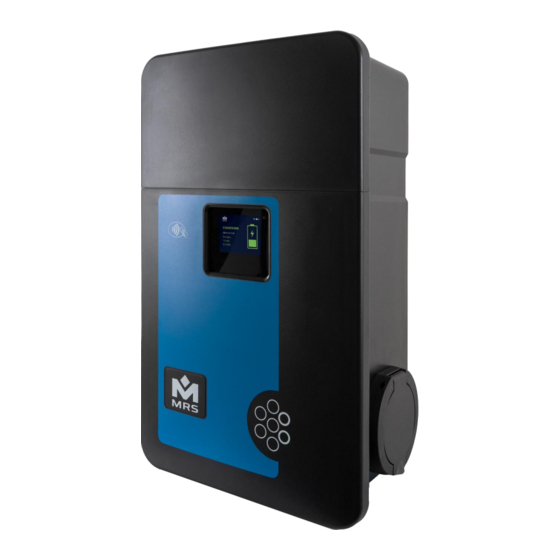
- Page 1 MCharger Connected S 22 kW Installation and operating manual...
- Page 2 About this manual The installation and operating manual is intended for the electrician who carries out the installation as well as for the persons who are to operate the product. Read the manual in full before starting to use the product. Save the manual after reading for future reference.
-
Page 3: Table Of Contents
Table of contents Introduction ............................. 1 Safety ............................... 1 General safety instructions ......................... 1 Qualification of personnel for installation and maintenance ............. 2 User's qualification ..........................2 Intended use ............................2 Service ..............................3 Nameplate ............................... 3 Scope of delivery ............................. 4 Installation ............................... - Page 4 Vehicle connected ..........................34 Charging ............................. 35 End of charging ..........................36 Maintenance, troubleshooting and decommissioning ................. 37 Maintenance ............................. 37 Manual updates..........................37 Cleaning ............................. 37 Error diagnosis ........................... 37 Reset ..............................39 Decommissioning ..........................40 Disposal instructions ......................... 40 CE marking and declaration of conformity ...................
-
Page 5: Introduction
Introduction Thank you for choosing our product! We have developed the MCharger together with the company Plastimat with the utmost care and we are of course also available to you after the purchase if you have any questions or problems. This manual contains all the necessary information for the installation and operation of the wallbox. -
Page 6: Qualification Of Personnel For Installation And Maintenance
Qualification of personnel for installation and maintenance Only suitably qualified specialist personnel (electrician) may install, commission, and maintain the wallbox. DANGER! Improper installation or repair of the wallbox can cause severe consequences, such as fire or severe or fatal injuries! User's qualification Only adults are allowed to use this wallbox. -
Page 7: Service
Service For technical service, please first contact the electrician who carried out the installation of the wallbox. Nameplate The nameplate on the bottom of the MCharger wallbox shows all relevant data of the wallbox. Here you will find e.g., type designation, serial number, date of manufacture (month/year), as well as the operating parameters of the wallbox. -
Page 8: Scope Of Delivery
Scope of delivery The wallbox is delivered in a custom-fit box. When unpacking, please make sure that you remove all parts from the box. If something is unexpectedly missing, please contact the supplier from whom you bought the wallbox immediately. NOTE: Check all parts for damage before the assembly. -
Page 9: Installation
Installation Installation site requirements Please check if the installation location: • is freely accessible and the wallbox display is easy to read even in incident light; • provides a flat mounting surface; • provides a sufficient load capacity; • provides a sufficiently dimensioned mounting surface; •... -
Page 10: Installation Of The Wallbox
Installation of the wallbox WARNING! Only appropriately qualified specialists (electricians) may install the wallbox. The following steps show where special attention should be paid to when mounting on the wall. All length measures are shown in millimetres. If the wallbox is not attached to a wall, please follow the instructions in the installation manual of the accessory. - Page 11 An additional cable of CAN interface can be inserted through the middle opening. Break out the opening with the screwdriver and hammer, then deburr the area with a knife. Use the small black rubber grommet for sealing. Cable from the bottom The required opening is provided in the housing.
- Page 12 Cable from the top Break out the opening on the top of the housing with the pliers and deburr it with a knife. Use the free space to lay a drip loop. Cable from the rear Break out the opening on the back of the housing with a screwdriver and a hammer and then deburr it with a knife.
- Page 13 For the installation from the bottom, use the left side mark on the installation rail. Draw the left mark. For the installation from the top, use the mark in the middle of the installation rail. Draw the middle mark. Copyright © 2022 Page 9...
- Page 14 For the installation from the rear, use the right side mark on the installation rail. Draw the right mark. Mark the holes for the installation rail. Use a spirit level! Page 10 Copyright © 2022...
- Page 15 Use the supplied cylinder head screws and dowels. Use a maximum screw diameter of 6 mm. Drill the appropriate holes for the installation rail with a distance of 90 mm. Use an 8 mm diameter drill bit. Attach the installation rail to the wall with dowels and screws.
- Page 16 Put the wallbox on the installation rail. Press the wallbox firmly to the wall. Draw the upper drill marks. Page 12 Copyright © 2022...
- Page 17 Use the supplied flathead screws and dowels. Use a maximum screw diameter of 6 mm. Remove the wallbox from the installation rail again. Drill the marked holes. Use an 8 mm diameter drill bit. Mount the dowels. Copyright © 2022 Page 13...
- Page 18 Insert the connection cable into the wallbox and use the appropriate grey rubber grommet. Put the wallbox on the installation rail. Secure the wallbox with two screws. Use the strain relief (small/large) for the installation type "from the bottom" or "from the top" of the connection cable.
-
Page 19: Connecting The Power Cable
Connecting the power cable WARNING! The installation may only be carried out by a qualified electrician. WARNING! Make sure again that the connection cable is disconnected from the mains. The electrical connection to the power grid must be carried out by a qualified electrician. Based on professional training, knowledge of the relevant standards and experience, he/she can assess the installation steps and identify any possible dangers. - Page 20 5 connection terminals are provided for connecting the power cable. The corresponding assignment is printed on the circuit board (PE – N – L1 – L2 – L3). In general, the following colors are set per phase: Marking Color Designation 1/3 phase Yellow-Green Protective...
- Page 21 The mostly single-phase charging of hybrid vehicles can lead to an uneven load on the outer connectors of a three-phase alternating current network if the phase connection is identical. The following connection diagram is recommended, taking into account the local infrastructural requirements: NOTE: The simultaneity factor cannot be reduced by an alternating connection! NOTE: Check that all wires have a firm fit in the terminal block.
-
Page 22: Mounting The Top Cover
When connecting the RS485 interface proceed in the same way as to connect the CAN bus. The pin assignment of the RS485 interface is shown in the graphic above. Switch SW7 is available for terminating the RS485 interface. NOTE: After connection or reconnection, the wallbox must be tested according to VDE 0105-100. -
Page 23: Setting Up The Wallbox
Setting up the wallbox Connection Connect to the wallbox Wi-Fi network using a computer, smartphone or tablet. The network will appear with the name (SSID) "Wallbox_XXXXXXX" as soon as you are close to the wallbox. A password is not required here. •... - Page 24 You are now on the dashboard. To connect the wallbox to your Wi-Fi network or to make settings for the connections, select the "Connectivity" tab on the left side of the menu bar: Make the settings for connecting your wallbox: •...
-
Page 25: Enable Automatic Updates
The IP address of your wallbox (Allocated IP Address) is displayed here. To get to the web interface of the wallbox, follow these steps: 1. Open your web browser. 2. Enter the following address in the address bar: https://”IP address” https://”IP address (use the Allocated IP address of your wallbox, e.g. -
Page 26: Create Users
Create users It is recommended to create the desired users of the wallbox directly after the initial registration. To do this, navigate to the tab "Users" via the menu items on the left side. Here you can create a user by clicking on the field "Add User". 1. -
Page 27: User Types
Now you can log in to the wallbox with the newly created user (username or e-mail address and password). The authorized functions are now available according to the selected user role. User types The following overview provides information about the user authorizations: User Regular User Technical... -
Page 28: General Settings
General settings Under the menu item "Wallbox Settings" you can make the basic settings of your wallbox. Which includes: • Name – naming your wallbox with it’s own name; • Time – time settings; • Geo Location - Automatic determination of the location (determination of the correct time zone);... -
Page 29: Charging History
After you have made the permanent or time-dependent settings, click on the "Reboot Wallbox" button to apply the settings. This will restart the wallbox. NOTE: The power that can be configured here refers to the three-phase connection of the wallbox! In single or two-phase operation, the power is reduced according to the number of phases. - Page 30 By pressing the download button you will be forwarded to the data export in the form of a PDF file. INFORMATION! In order to be able to carry out a data export, you need an internet connection for the wallbox which you can use for the Data transfer activation.
-
Page 31: Loadbalancing
Loadbalancing To operate several wallboxes in one network and at the same time protect the infrastructure from overloading, you can use the automatic load balancing function. All you have to do is connect the wallboxes via the CAN interface. When using the CAN bus, pay attention to the correct termination of your wallboxes and the maximum cable length of the bus line. -
Page 32: Master / Slave Set-Up
If it is necessary to approach a wallbox via a stub cable, it is important to keep the line as short as possible. Stub cables should not be longer than 10 meters. Stub cables reduce the maximum bus range. Wallbox 2 Wallbox 3 SW5 = 0 SW5 = 0... -
Page 33: Master Configuration
Master configuration In order to operate your wallboxes in a network, first start with the configuration of the master. To do this, select the “Add New Device” button under the “Load Balance” menu item. To create a master, enter the number 0 in the "Slave ID" field. The "Device ID" can be found under the menu item "Device Info". -
Page 34: Prioritization And Load Sharing
If a slave is deactivated via the master, it is displayed as follows (see Slave 2): Prioritization and load sharing When load balancing the wallbox, different priorities can be assigned to the individual wallboxes. Priorities A, B and C are available. Priority C is preset by default. - Page 35 If a wallbox is given Priority A, it will be allocated all of the energy required when charging is requested. The other participants are throttled according to their priority. INFORMATION! Ensure that not more than one wallbox in a charging network is configured with the priority A! Copyright ©...
-
Page 36: Ocpp
OCPP To connect the wallbox to a back-end system via OCPP v1.6, you can enter the access data provided by your back end provider under the “Open Charge Point Protocol (OCPP)” option in the “Wallbox Settings” section. By default Port 443 is used for this. You can get the exact connection parameters from your back-end provider. -
Page 37: Operating Instructions
Operating instructions General Before using the wallbox, the suitability of the vehicle for charging with it must be checked. Park the electric vehicle in such a way that you can easily reach the charging connection on the vehicle and the wallbox with the charging plugs of the charging cable. Furthermore, it must be ensured that the charging cable cannot be run over by your own vehicle or another vehicle, while it is being charged, in order to avoid damage to the cable. -
Page 38: Vehicle Connected
A connection icon will also appear in the upper right corner of the display. Icon Designation Wi-Fi Wi-Fi AP (Access Point) Cloud Connection The Wi-Fi, Wi-Fi AP, or Cloud icon does not appear automatically when enabled. The respective symbol appears on the display when a connection has been successfully established and remains visible on the display as long as the connection is active. -
Page 39: Charging
Charging As soon as the charging process starts, the vehicle locks the plug of the charging cable in its socket. This prevents the charging process from being interrupted prematurely by unplugging the charging cable. The charging process is started by connecting the vehicle to the wallbox. If the process does not start automatically, please check whether the vehicle has also released the charging process. -
Page 40: End Of Charging
End of charging When the charging process is finished, this is indicated with a tick in the battery on the display. Charging may be terminated when the battery is fully charged or when the vehicle has stopped or paused charging. If the charging process is continued after a pause, the display changes back to the charging process. -
Page 41: Maintenance, Troubleshooting And Decommissioning
If your wallbox does not have an Internet connection, you can also install updates locally. To do so, download the current software from the website https://www.mrs- electronic.com/solutions/e- mobility. Connect to the wallbox. If the wallbox has not been integrated into a network, use the WLAN provided by the wallbox. - Page 42 Error ID Description Troubleshooting 0001 A fault current has been detected DANGER! Disconnect the power supply to the wallbox and secure it against being switched on again. Then disconnect the charging cable from the vehicle. Contact the electrician who carried out the installation of the wallbox.
-
Page 43: Reset
wallbox supplier. Provide the corresponding error IDs from the vehicle and the wallbox. 0080 Internal error detected Disconnect the charging cable from the vehicle and start the charging process again. If the error persists, refer to the operating instructions of your vehicle and contact your supplier of the wallbox or the vehicle brand dealership. -
Page 44: Decommissioning
The slide switch SW4 has to be toggled ten times. The timeout for each toggle is five seconds. If there is no toggle within five seconds, the toggle counter is reset. After ten toggles, a five-second beep sounds. After the long beep, a sequence of short beeps will continue for five seconds. -
Page 45: Ce Marking And Declaration Of Conformity
CE marking and declaration of conformity MRS Electronic GmbH & Co. KG Hersteller Klaus-Gutsch-Straße 7 Manufacturer D-78628 Rottweil Germany Die alleinige Verantwortung für die Ausstellung dieser Konformitätserklärung trägt der Hersteller. This declaration of conformity is issued under the sole responsibility of the manufacturer. -
Page 46: Technical Data
Technical Data Functions ✓ Charging functionality up to 22 kW (1-3 ph) ✓ Easy installation ✓ Type 2 charging socket ✓ Status display showing charging duration, kW and kWh ✓ Acoustic warning buzzer ✓ RCD integrated (6 mA DC) ✓ SW-Update via OTA (LAN / WLAN) ✓... -
Page 47: Dimensions
Dimensions Copyright © 2022 Page 43... -
Page 48: Copyright
Contacts / SERVICE Do you need any help? Please contact our support team: Mon - Fr: 09:00 - 15:00 (CET) Phone: +49 741 2807 1020 Email: emobility@mrs-electronic.com Website: www.mrs-electronic.com 503516 – V.1.2 Page 44 Copyright © 2022...
Need help?
Do you have a question about the MCharger Connected S and is the answer not in the manual?
Questions and answers