Table of Contents
Advertisement
Quick Links
Operation Manual JY305
The latest software download link:
JY305 Install Video:
JY305 calibration training video
JY305 related video:
Add: Room 213-214, Building 1, Mingliang Science Park, No. 88, Zhuguang North Road, Taoyuan
Street, Nanshan District, Shenzhen, China,518055 Tel: +86-075586276295
tt s
yo t be om at
Smajayu 2.0
2
Advertisement
Table of Contents

Related Manuals for SMAJAYU JY305


Summary of Contents for SMAJAYU JY305
- Page 1 The latest software download link: JY305 Install Video: tt s yo t be om at JY305 calibration training video JY305 related video: Smajayu 2.0 Add: Room 213-214, Building 1, Mingliang Science Park, No. 88, Zhuguang North Road, Taoyuan Street, Nanshan District, Shenzhen, China,518055 Tel: +86-075586276295...
-
Page 2: Table Of Contents
Content 1、Introduction..........2、Mai ................. 4 2.1 Assembly and Installation ............3、Device Switching .................. 6 4、Equipment Debugging ................7 4.1、Main Interface Introduction ............7 4.2、Vehicle Parameters ..............9 4.3、Base Station Connection ............10 4.4、Device Registration ..............12 4.5、Equipment Debugging ............. 13 4.5.1、Mode Selection ............. 14 4.5.2、Roll Debugging .............18 4.5.3、Error Debugging ............ - Page 3 5.5、Day and Night Mode Switching ..........25 5.6、Dimension Switching ...............26 5.7、Camera ..................26 6、Equipment Specifications ..............27 6.1、T100 Tablet ................27 6.1.1、Technical Features ............28 6.1.2、Technical Parameter ............29 6.1.3、Interface Definition ............30 6.2、 2 Motor ................32 6.2.1、Introduction ..............32 6.2.2、Technical Features ............32 6.2.3、Technical Parameter ............33 6.2.4、Interface Definition ............34 6.3、...
-
Page 4: 2、Mai
1、Introduction 2、Main Accessories This equipment mainly includes five parts: tablet T100, drive control motor , receiver , angle sensor (optional), and connecting cable. Details as the list below: Description Picture Remark Drive control motor spline Optional steering wheel 41cm bracket Optional Bracket screw pack dd Room 213-214, Building 1, Mingliang Science Park, No. - Page 5 tablet T100 RAM bracket T100-Fourth generation main line switch line Power supply extension line GNSS Receiver Mounting plate radio antenna Power supply line Waterproof camera Camera extension cable Manual switch dd Room 213-214, Building 1, Mingliang Science Park, No. 88, Zhuguang North Road, Taoyuan Street, Nanshan District, Shenzhen, hina, 18...
- Page 6 Manual switch cable Coaxial angle sensor Angle sensor cable Autopilot screw pack dd Room 213-214, Building 1, Mingliang Science Park, No. 88, Zhuguang North Road, Taoyuan Street, Nanshan District, Shenzhen, hina, 18...
-
Page 7: Assembly And Installation
Assembly and Installation 2.1.1 EMS2 installation The EMS2 Motor Wheel is an electric motor steering wheel. The most important part is the spline sleeve, which is based on the selection of the vehicle model refer to the table in Appendix. Please indicate your vehicle model before placing order of this system. - Page 8 Logo Cover Steering Wheel Spline Sleeve Flange Electric Motor Bracket Screw Figure 2.2 Descriptions of the EMS2 assembly components The detailed steps of installing EMS2 Motor Wheel are shown as below. 1) Prepare the components needed for EMS2 Electric Motor. Figure 2.3 Components needed for electric motor 2) Use the corresponding screws in the package to fixate dd Room 213-214, Building 1, Mingliang Science Park, No.
- Page 9 the bracket and motor on the vehicle to replace the original steering wheel. Spline Sleeve Flange EMS2 Electric Motor Figure 2.4 Installation example of electric motor Figure 2.5 Installation example of bracket for fixating EMS2 Motor Wheel 3) Use screws to install the steering wheel and Loge cover. dd Room 213-214, Building 1, Mingliang Science Park, No.
- Page 10 Figure 2.6 Installation example of EMS2 Motor Wheel 4) Now the installation of EMS2 Motor Wheel is completed. It should be connected to the main cable after all parts are assembled properly. The cables connection refers to section 2.1. Cables Connection. dd Room 213-214, Building 1, Mingliang Science Park, No.
- Page 11 2.1.2 Angle Sensor installation The detailed steps of installing Angle Sensor are shown as below. 1) Prepare the components needed for installing Angle Sensor. Figure 2.7 Components needed to install angle sensor 2) Install angle sensor on left front wheel. Take off screw on left front wheel and install angel sensor board, notes plane with screw holes on angel should face to vehicle body when installation.
- Page 12 3) Adjust the position of angle sensor to be properly installed. Find the best position and make sure angle sensor could turn in normally. Then, use screw fix angle sensor bracket. Figure 2.9 Possible position of angle sensor – 1 dd Room 213-214, Building 1, Mingliang Science Park, No.
- Page 13 Figure 2.10 Fix angle sensor – 2 4) Extend board could be used if this part do not have a screw could use for fix angel sensor bracket. Figure 2.11 Installation example of angle sensor 5) Now the installation of Angle Sensor is completed. It should be connected to the main cable after all parts are assembled properly.
- Page 14 2.1.3 Cables Connection The cables connection should be paid much attention during assembly as there are various connectors on the main cable which is shown below. Figure 2.16 Main Cable with multiple connectors dd Room 213-214, Building 1, Mingliang Science Park, No. 88, Zhuguang North Road, Taoyuan Street, Nanshan District, Shenzhen, hina, 18...
- Page 15 Figure 2.17 Power extension cable with two wires The current hardware supports 12V and 24V power supplies Figure 2.18 Angle Sensor The Attitude Sensor (IMU) is optional. It is only required when the angle sensor is not able to be installed on the vehicle. Figure 2.20 Attitude Sensor (IMU) Figure 2.19 Cable for Attitude Sensor (IMU) Figure 2.21 Power Switch with cable...
- Page 16 Second Second Second Second Antenna Antenna Camera Data Cable 4G Antenna Radio/Switch Primary Antenna Figure 2.23 T100 Control Tablet connects to main cable and two antennas Normally the T100 Control Tablet is installed in the control room of the vehicle using the bracket which is shown as below. Figure 2.24 Bracket for T100 Control Tablet dd Room 213-214, Building 1, Mingliang Science Park, No.
-
Page 17: 3、Device Switching
3、Device Switching After opening the software for the first time, we need to switch it to single antenna mode, as shown in the figure below: ote: dd Room 213-214, Building 1, Mingliang Science Park, No. 88, Zhuguang North Road, Taoyuan Street, Nanshan District, Shenzhen, hina, 18... -
Page 18: 4、Equipment Debugging
4、Equipment Debugging This chapter mainly introduces the use of software debugging. 4.1、Main interface introduction Pic.4.1 Main interface icon introduction: Description Icon Camera switch button Main interface mode switch Satellite status display Signal status display dd Room 213-214, Building 1, Mingliang Science Park, No. 88, Zhuguang North Road, Taoyuan Street, Nanshan District, Shenzhen, hina, 18... - Page 19 time display Error display Device real-time speed Job width display Work area display Signal status display Zoom in / out button on the main interface Main interface 2D and 3D view switching button Return to current position button AB line setting and editing button start and end button Equipment status and self-test button System settings...
-
Page 20: Vehicle Parameters
Remark: ( )Switching between day and night modes on the main interface. ( )Signal status Fixed: Connect to the base station, the signal is normal. Single point: The base station is not connected. Floating: Connect to the base station, the signal is abnormal. 4.2、Vehicle parameters After the hardware equipment is installed, we need to set the vehicle model for the software. -
Page 21: Base Station Connection
Pic.4-2-2 We enter the vehicle parameters, and after returning to the main interface, the current parameters will be saved under the current vehicle. Therefore, the current vehicle type, brand, and model can be added to the current vehicle before entering the parameters. 4.3、Base station connection The device needs to be connected to the base station to work. - Page 22 Pic.4-3-1 (1) External data: the way to obtain base station data by connecting D10 radio module and D20 network module ( series basically does not use this mode). (2) CORS: The way to connect to the network base station through an account.
-
Page 23: Device Registration
Pic.4-3-2 4.4、Device registration After the device is installed, you need to provide the corresponding information to complete the device registration and function activation. The required information is as follows: The SN number of the T100 tablet. The SN number of the receiver The brand and model of the tractor name can be used, but different customers cannot use it repeatedly). -
Page 24: Equipment Debugging
4.5、Equipment debugging Device debugging is divided into two modes: angle sensor mode, gyroscope mode. Before debugging, we need to manually drive forward at a speed of about 3km/h, Wait until the prompt on the main interface disappears to complete the initialization. Ti : Pic.4-5-1 Note: after each power supply is re-supplied, it is necessary to... - Page 25 Pic.4-5-2 (2)Select angle sensor mode Switch the system to gyroscope mode according to the pattern below. Pic.4-5-3 dd Room 213-214, Building 1, Mingliang Science Park, No. 88, Zhuguang North Road, Taoyuan Street, Nanshan District, Shenzhen, hina, 18...
- Page 26 After the angle sensor selection is completed, we also need to select the installation model of the angle sensor, etc. First select the angle sensor model, the common model is 90°. But 120° and 360° angle sensors are also used. Pic.4-5-4 Remark: Before installing the angle sensor, pay attention to checking the model of...
- Page 27 Then select the installation of the angle sensor. Pic.4-5-6 e a : After selecting the installation location, make sure to turn the steering wheel to the left to decrease the alignment value. Then turn the steering eel to t e i t to in ease t e ali nment al e Installation osition i it is installed on t e i t eel sele t t e i t eel i it is installed on t e le t...
- Page 28 The centering angle of the 90° model is about 60°, the 360° model is about 240°, and the 120° model is about 90°. et to et t e t e ente in an le and an e t e man ally ente al e to t e eal time al e The above content is a reference value, as long as the steering wheel is turned left or right, the centering value will continue to change before the...
- Page 29 1: Width of crop class 1 b: Joint width (distance between two adjacent seed rows) 2: Width of crop class 2 c: Distance from implement to rear wheel d2: Implement offset distance (left or right) In general, d2 is set to 0. 5 3、...
-
Page 30: Error Debugging
Note: it is best to debug twice continuously to ensure that the difference between the two results is no more than 0.3, and the result range is - 1 ~ 1. 4.5.4、Error Debugging According to the AB line setting in chapter 4.6, then set the AB line, and observe the screen error change after turning on the navigation. -
Page 31: Ab Line Setting
Pic.4-5-11 4.6、AB line setting In the new plot operation, we need to set the AB line first, set the A point at the head of the plot, and set the B point at the end of the plot, as shown in the following figure:... - Page 32 The software operation is shown in the figure below: Pic.4-6-2 When you reach the headland, click point A, and when you reach the end of the land, click point B, and then a naming window will pop up. The drop-down window can improve the information inside. First, you can set the name of the AB line.
-
Page 33: 5、Function Introduction
5、Function Introduction This section mainly introduces the use of some additional functions of the software. 5.1、Language Selection Select the language in the system settings. Customers only need to select the appropriate language to use. Now the software includes English, Russian, Polish, French, Turkish, Serbian and Spanish. Pic.5-1 Remarks: If other languages are required, the company can provide Chinese and English language packages for customers to choose, and... -
Page 34: Time Selection
Remarks: When purchasing equipment, the software can be continuously upgraded for free, but before upgrading, be sure to ask the company's technicians if they can upgrade to avoid unnecessary errors. 5.3、Time Selection The software defaults UTC+8, and customers select the corresponding time display according to the specific time zone of the location. -
Page 35: Day And Night Mode Switching
5.5、Day and Night Mode Switching mode of the main interface, and you can select the appropriate interface according to different time operations. Pic.5-5 5.6、Dimension Switching The software can switch the dimension display (3D and 2D) of the main interface according to the customer's preference, and the software defaults to the 3D model display. -
Page 36: 6、Equipment Specifications
Pic.5-7 6、Equipment Specifications This section mainly introduces the parameters of the main hardware motors, tablet, and receiver. 6.1、T100 Tablet T100 tablet is an industrial-grade vehicle Android display control panel developed and produced by . It can ensure the operation in harsh environment. -
Page 37: Technical Features
6.1.1、Technical Features (1) Powerful, stable and reliable automotive-grade processor, CPU: ARM Cortex-A7, 1.5GHz; (2) Product design in strict accordance with industrial rules, in line with IP66 technical specifications, and adapt to harsh operating environments in the wild; (3) Built-in super powerful 4-core processor, main frequency 1.5GHz, onboard 2GB memory, 16GB storage;... - Page 38 Physical properties Working temperature: -40℃~+70℃ Storage temperature: -55℃~+85℃ Physical size: 281mm×181mm×42mm Resolution: 1024×600P Screen size: 10.1 inches Weight: 1.56kg Protection class: IP66 Shock and Vibration: MIL-STD-810G Data interface RS232×2 RS485×1 CAN×1 USB2.0×1 DC IN×1 Audio output×1 DI×2,DO×2 12V DC OUT×1 Analog camera input×2 RJ45×1 dd Room 213-214, Building 1, Mingliang Science Park, No.
-
Page 39: Interface Definition
Performance index een si e la e s een in es een b i tness i b i tness nits i eless omm ni ation omm ni ation inte a e et o system all et om 6.1.3、Interface Definition PORT1 CVBS12V CVBSIN2 CVBSIN1... -
Page 40: Motor
PORT3 RS485A RS485B AUDIO-LINEOUT DC12V-OUT1 RJ45-TX+ RJ45-TX- RJ45-RX- RJ45-RX+ DC12V-OUT2 INPUT-GPIO2 Remark: SMA connector 4G to connect 4G antenna. 2 GNSS connector to connect UBLOX antenna (not required for de i e e te nal 2 o t onne ted to t e moto e te nal 2 o t 2 2A onne ted to... -
Page 41: Technical Parameter
、Technical eat res environment. (4) Integrated drive and control design, beautiful appearance, reduce cable connection. 6.2.3、Technical Parameter Electrical parameters Extreme short-time working voltage: DC6-35V Rated current: 12.5A Stall current: 25A Rated voltage: 12V Logic power supply range: none Communication protocol: ModBUS, CAN Encoder resolution: 53248 lines Encoder interface (protocol): parallel, no protocol Maximum output frequency of encoder: 200KHZ... -
Page 42: Interface Definition
Maximum torque: 9N*m; (20N*m optional) Guaranteed speed of continuous operation: 100rpm Maximum free-running error: no reducer, no free-running error Data interface RS232 2 CAN AD convert 6.2.4、Interface definition Function Note +12V 232-RXD 232-TXD 232-GND Burn mode SENSOR OUT AD sampling SENSOR 0V land SENSOR +5V... -
Page 43: Receiver
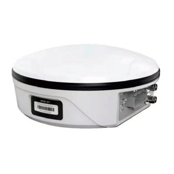
6.3、 Receiver GNSS receiver is a new multi-function high-precision GNSS receiver, with built-in dual-antenna Beidou/GNSS high-precision board, radio communication module, inertial navigation combination module, 4G module, Bluetooth module, etc. 6.3.1、Technical Features (1) High precision and low power consumption, using Beidou, GPS, GLONASS, Galileo and other four-system multi-frequency systems. -
Page 44: Technical Parameter
6.3.2、Technical Parameter Signal tracking BDS:B1、B2、B1I、B2I GPS:L1、L2 GLONASS:L1、L2 Galileo:E1、E5b QZSS: L1、L2 Cold start time: <25s Initialization time: <5s (typ.) RTK initialization reliability: >99.9%Recapture: <1s Accuracy Index (1) Single-point positioning: Plane: 1.5m dd Room 213-214, Building 1, Mingliang Science Park, No. 88, Zhuguang North Road, Taoyuan Street, Nanshan District, Shenzhen, hina, 18... - Page 45 Electrical parameters Power consumption: ≤4.0W Supply voltage: 9~36V DC Physical properties Working temperature: -45℃~+75℃ Storage temperature: -55℃~+85℃ Size: 181.4mm×181.1mm×70mm Indicator light: 1 power light, 1 differential signal light, 1 satellite light Data interface Data output: NMEA-0183, binary code Data refresh rate: 1~20Hz optional Baud rate: 9600~921600 DEUTSCH connector: including one power supply, one RS232, two CAN...
-
Page 46: Interface Definition
6.3.3、Interface Definition definition port 9-36V DC CONFIG dd Room 213-214, Building 1, Mingliang Science Park, No. 88, Zhuguang North Road, Taoyuan Street, Nanshan District, Shenzhen, hina, 18...
Need help?
Do you have a question about the JY305 and is the answer not in the manual?
Questions and answers