Table of Contents
Advertisement
Quick Links
B660M DS3H AX DDR4
B660M DS3H DDR4
User's Manual
Rev. 1301
B660M DS3H AX DDR4 B660M DS3H DDR4
To reduce the impacts on global warming, the packaging materials of this product
are recyclable and reusable. GIGABYTE works with you to protect the environment.
For more product details, please visit GIGABYTE's website.
Advertisement
Table of Contents

Subscribe to Our Youtube Channel
Related Manuals for GIGA-BYTE TECHNOLOGY B660M DS3H AX DDR4


Summary of Contents for GIGA-BYTE TECHNOLOGY B660M DS3H AX DDR4
- Page 1 B660M DS3H DDR4 User's Manual Rev. 1301 B660M DS3H AX DDR4 B660M DS3H DDR4 For more product details, please visit GIGABYTE's website. To reduce the impacts on global warming, the packaging materials of this product are recyclable and reusable. GIGABYTE works with you to protect the environment.
- Page 2 Copyright © 2023 GIGA-BYTE TECHNOLOGY CO., LTD. All rights reserved. The trademarks mentioned in this manual are legally registered to their respective owners. Disclaimer Information in this manual is protected by copyright laws and is the property of GIGABYTE. Changes to the specications and eatures in this manual may be made by GIGABYTE without prior notice.
-
Page 3: Table Of Contents
Table of Contents Chapter 1 Product Introduction..................4 Motherboard Layout..................4 Box Contents....................5 Chapter 2 Hardware Installation ..................6 Installation Precautions..................6 Product Specications..................7 Installing the CPU and CPU Cooler ............... 11 Installing the Memory..................14 Installing an Expansion Card ................. 15 Back Panel Connectors.................. -
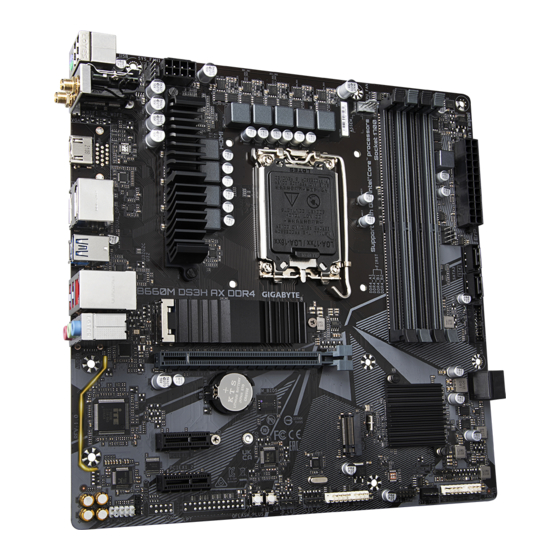
Page 4: Chapter 1 Product Introduction
B660 PCIEX1_2 CODEC QFLED USB 2.0 Hub RST_SW SPDIF_O COM k LED_C F_USB2 SYS_FAN3 QFLASH_PLUS F_AUDIO LPT k D_LED F_USB1 SPI_TPM F_PANEL Temperature sensor j Only for B660M DS3H AX DDR4. k Only for B660M DS3H DDR4. - 4 -... -
Page 5: Box Contents
Box Contents 5 B660M DS3H AX DDR4 or B660M DS3H DDR4 motherboard 5 User's Manual 5 I/O Shield 5 Two SATA cables 5 One antennaj 5 M.2 screws * The box contents above are for reference only and the actual items shall depend on the product package you obtain. -
Page 6: Chapter 2 Hardware Installation
Chapter 2 Hardware Installation Installation Precautions The motherboard contains numerous delicate electronic circuits and components which can become damaged as a result of electrostatic discharge (ESD). Prior to installation, carefully read the user's manual and follow these procedures: • Prior to installation, make sure the chassis is suitable for the motherboard. •... -
Page 7: Product SpeciCations
BLUETOOTH 5.2 Support for 11ax 160MHz wireless standard and up to 2.4 Gbps data rate (Actual data rate may vary depending on environment and equipment.) j Only for B660M DS3H AX DDR4. k Only for B660M DS3H DDR4. - 7 -... - Page 8 1 x S/PDIF Out header Š 1 x Q-Flash Plus button Š 1 x reset button Š 1 x reset jumper Š 1 x Clear CMOS jumper j Only for B660M DS3H AX DDR4. k Only for B660M DS3H DDR4. - 8 -...
- Page 9 unctions o each application may also vary depending on motherboard specications. @BIOS EasyTune RGB Fusion Smart Backup System Information Viewer Š Support for Q-Flash Plus Support for Q-Flash Š Support for Xpress Install Š j Only for B660M DS3H AX DDR4. k Only for B660M DS3H DDR4. - 9 -...
- Page 10 * GIGABYTE reserves the right to make any changes to the product specications and product-related inormation without prior notice. B660M DS3H AX DDR4 B660M DS3H DDR4 Please visit GIGABYTE's website for support lists of CPU, memory modules, SSDs, and M.2 devices.
-
Page 11: Installing The Cpu And Cpu Cooler
Installing the CPU and CPU Cooler Read the following guidelines before you begin to install the CPU: • Make sure that the motherboard supports the CPU. (Go to GIGABYTE's website for the latest CPU support list.) • Always turn off the computer and unplug the power cord from the power outlet before installing the CPU to prevent hardware damage. - Page 12 B. Installing the CPU Follow the steps below to correctly install the CPU into the motherboard CPU socket. Finger Tab jGently press the CPU socket lever handle down and away from the socket. kCompletely lift up the CPU socket locking lever.
- Page 13 C. Installing the CPU Cooler Be sure to install the CPU cooler after installing the CPU. (Actual installation process may differ depending the CPU cooler to be used. Refer to the user's manual for your CPU cooler.) Apply an even and thin layer of thermal grease on the surface of the installed CPU.
-
Page 14: Installing The Memory
Installing the Memory Read the following guidelines before you begin to install the memory: • Make sure that the motherboard supports the memory. It is recommended that memory of the same capacity, brand, speed, and chips be used. (Go to GIGABYTE's website for the latest supported memory speeds and memory modules.) •... -
Page 15: Installing An Expansion Card
Installing an Expansion Card Read the following guidelines before you begin to install an expansion card: • Make sure the motherboard supports the expansion card. Carefully read the manual that came with your expansion card. • Always turn off the computer and unplug the power cord from the power outlet before installing an expansion card to prevent hardware damage. -
Page 16: Back Panel Connectors
HDMI/DisplayPort. (The item name may differ depending on your operating system.) (Note) To enable the Q-Flash Plus function, please navigate to the "Unique Features" page of GIGABYTE's website for more information. j Only for B660M DS3H AX DDR4. k Only for B660M DS3H DDR4. - 16 -... - Page 17 USB 3.2 Gen 1 Port The USB 3.2 Gen 1 port supports the USB 3.2 Gen 1 specication and is compatible to the USB 2.0 specication. Use this port or USB devices. USB Type-C Port, with USB 3.2 Gen 2 Support ®...
-
Page 18: Internal Connectors
Internal Connectors 10 18 2019 6 7 ATX_12V_2X4 F_U32 F_USB1/F_USB2 CPU_FAN SPI_TPM SYS_FAN1/2/3 COM k SATA3 4/5/6/7 LPT k D_LED LED_C CLR_CMOS M2A_CPU/M2P_SB SPDIF_O F_PANEL RST_SW/RST F_AUDIO QFLASH_PLUS k Only for B660M DS3H DDR4. Read the following guidelines before connecting external devices: •... - Page 19 1/2) ATX_12V_2X4/ATX (2x4 12V Power Connector and 2x12 Main Power Connector) With the use of the power connector, the power supply can supply enough stable power to all the components on the motherboard. Beore connecting the power connector, rst make sure the power supply is turned off and all devices are properly installed.
- Page 20 3/4) CPU_FAN/SYS_FAN1/2/3 (Fan Headers) All fan headers on this motherboard are 4-pin. Most fan headers possess a foolproof insertion design. When connecting a fan cable, be sure to connect it in the correct orientation (the black connector wire is the ground wire). The speed control function requires the use of a fan with fan speed control design. For optimum heat dissipation, it is recommended that a system fan be installed inside the chassis.
- Page 22 8) M2A_CPU/M2P_SB (M.2 Socket 3 Connectors) The M.2 connectors on the motherboard support only M.2 PCIe SSDs. M2A_CPU M2P_SB Follow the steps below to correctly install an M.2 SSD in the M.2 connector. Step 1: Locate the M.2 connector where you will install the M.2 SSD, use a screwdriver to unfasten the screw on the heatsink and then remove the heatsink.
- Page 23 9) F_PANEL (Front Panel Header) Connect the power switch, reset switch, speaker, chassis intrusion switch/sensor and system status indicator on the chassis to this header according to the pin assignments below. Note the positive and negative pins before connecting the cables. Power LED Power Switch Speaker...
- Page 24 10) F_AUDIO (Front Panel Audio Header) The ront panel audio header supports High Denition audio (HD). You may connect your chassis ront panel audio module to this header. Make sure the wire assignments of the module connector match the pin assignments of the motherboard header. Incorrect connection between the module connector and the motherboard header will make the device unable to work or even damage it.
- Page 25 12) F_USB1/F_USB2 (USB 2.0/1.1 Headers) The headers conorm to USB 2.0/1.1 specication. Each USB header can provide two USB ports via an optional USB bracket. For purchasing the optional USB bracket, please contact the local dealer. Pin No. Denition Power (5V) Power (5V) USB DX- USB DY-...
- Page 26 14) COM (Serial Port Header) k The COM header can provide one serial port via an optional COM port cable. For purchasing the optional COM port cable, please contact the local dealer. Pin No. Denition NDCD- NSIN NSOUT NDTR- NDSR- NRTS- NCTS- NRI-...
- Page 27 16) BAT (Battery) The battery provides power to keep the values (such as BIOS congurations, date, and time inormation) in the CMOS when the computer is turned off. Replace the battery when the battery voltage drops to a low level, or the CMOS values may not be accurate or may be lost. You may clear the CMOS values by removing the battery: 1.
- Page 28 18) SPDIF_O (S/PDIF Out Header) This header supports S/PDIF digital output, which allows you to connect a S/PDIF digital audio cable to output digital audio from your motherboard to the supported audio devices. For information about connecting the digital audio cable, carefully read the manual for your audio devices. Pin No.
- Page 29 20) QFLASH_PLUS (Q-Flash Plus Button) Q-Flash Plus allows you to update the BIOS when your system is off (S5 shutdown state). Save the latest BIOS on a USB thumb drive and plug it into the dedicated port, and then you can now fash the BIOS automatically by simply pressing the Q-Flash Plus button.
-
Page 30: Chapter 3 Bios Setup
Chapter 3 BIOS Setup BIOS (Basic Input and Output System) records hardware parameters of the system in the CMOS on the motherboard. Its major functions include conducting the Power-On Self-Test (POST) during system startup, saving system parameters and loading operating system, etc. BIOS includes a BIOS Setup program that allows the user to modiy basic system conguration settings or to activate certain system eatures. - Page 31 Startup Screen: The following startup Logo screen will appear when the computer boots. Function Keys Function Keys: <DEL>: BIOS SETUP\Q-FLASH Press the <Delete> key to enter BIOS Setup or to access the Q-Flash utility in BIOS Setup. <F12>: BOOT MENU Boot Menu allows you to set the rst boot device without entering BIOS Setup.
-
Page 32: Chapter 4 Installing The Operating System And Drivers
Chapter 4 Installing the Operating System and Drivers Operating System Installation With the correct BIOS settings, you are ready to install the operating system. If you want to install an operating system on a RAID volume, you need to install the Intel RST VMD Controller ®... -
Page 33: Drivers Installation
Drivers Installation After you install the operating system, a dialog box will appear on the bottom-right corner of the desktop asking if you want to download and install the drivers and GIGABYTE applications via APP Center. Click Install to proceed with the installation. (In BIOS Setup, make sure Settings\IO Ports\APP Center Download & Install Confguration\APP Center Download &... -
Page 34: Chapter 5 Appendix
Chapter 5 Appendix Confguring a RAID Set RAID Levels RAID 0 RAID 1 RAID 5 RAID 10 Minimum Number of Hard ≥2 ≥3 Drives Number of hard (Number of hard (Number of hard Size of the smallest Array Capacity drives * Size of the drives -1) * Size of drives/2) * Size of the drive... -
Page 35: Regulatory Notices
Supplier's Declaration of Conformity 47 CFR § 2.1077 Compliance Information Product Name: Motherboard Trade Name: GIGABYTE Model Number: B660M DS3H AX DDR4/B660M DS3H DDR4 Responsible Party – U.S. Contact Information: G.B.T. Inc. Address: 17358 Railroad street, City Of Industry, CA91748 Tel.: 1-626-854-9338 Internet contact information: https://www.gigabyte.com... - Page 36 European Union (EU) Community Waste Electrical & Electronic Equipment CE declaração de conformidade (WEEE) Directive Statement Este produto com a marcação CE estão em conformidade com das seguintes GIGABYTE will ulll the national laws as interpreted rom the 2012/19/EU WEEE Diretivas UE: Diretiva Baixa Tensão 2014/35/EU;...
- Page 37 To identify your Motherboard version or revision number, look for "REV: X.X" printed on the PCB on the top left corner of the Motherboard. For example, "REV:1.0" means the revision of the motherboard is 1.0. Motherboard revision no.: Wireless module manufacturer, model name: B660M DS3H AX DDR4 rev. 1.0 Intel Corporation AX201NGW ®...
-
Page 38: Contact Us
Contact Us GIGA-BYTE TECHNOLOGY CO., LTD. Address: No.6, Baoqiang Rd., Xindian Dist., New Taipei City 231 TEL: +886-2-8912-4000, FAX: +886-2-8912-4005 Tech. and Non-Tech. Support (Sales/Marketing) : https://esupport.gigabyte.com WEB address (English): https://www.gigabyte.com WEB address (Chinese): https://www.gigabyte.com/tw GIGABYTE eSupport • To submit a technical or non-technical (Sales/Marketing) question, please link to: https://esupport.gigabyte.com...
Need help?
Do you have a question about the B660M DS3H AX DDR4 and is the answer not in the manual?
Questions and answers