Table of Contents
Advertisement
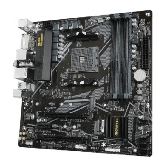
B550M DS3H AC
B550M DS3H
User's Manual
Rev. 1701
GIGABYTE will reduce paper use in order to ulll the responsibilities o a global citizen.
Also, to reduce the impacts on global warming, the packaging materials o this product
are recyclable and reusable. GIGABYTE works with you to protect the environment.
For more product details, please visit GIGABYTE's website.
Advertisement
Table of Contents

Related Manuals for GIGA-BYTE TECHNOLOGY B550M DS3H AC


Summary of Contents for GIGA-BYTE TECHNOLOGY B550M DS3H AC
- Page 1 B550M DS3H AC B550M DS3H User's Manual Rev. 1701 GIGABYTE will reduce paper use in order to ulll the responsibilities o a global citizen. Also, to reduce the impacts on global warming, the packaging materials o this product are recyclable and reusable. GIGABYTE works with you to protect the environment.
- Page 2 Copyright © 2023 GIGA-BYTE TECHNOLOGY CO., LTD. All rights reserved. The trademarks mentioned in this manual are legally registered to their respective owners. Disclaimer Information in this manual is protected by copyright laws and is the property of GIGABYTE. Changes to the specifcations and eatures in this manual may be made by GIGABYTE without prior notice.
-
Page 3: Table Of Contents
Table of Contents Chapter 1 Product Introduction..................4 Motherboard Layout..................4 Chapter 2 Hardware Installation ..................5 Installation Precautions..................5 Product Specications..................6 Installing the CPU .................... 9 Installing the Memory..................10 Installing an Expansion Card ................. 11 Back Panel Connectors.................. 12 Internal Connectors.................. -
Page 4: Chapter 1 Product Introduction
SYS_FAN1 LED_CPU M_BIOS AUDIO PCIEX16 B550M DS3H (AC) Realtek ® PCIEX1 GbE LAN B550 ® CODEC PCIEX4 Super I/O CLR_CMOS QFLED F_U32 SYS_FAN2 D_LED1 F_AUDIO LED_C1 F_USB1 F_PANEL QFLASH_PLUS Temperature sensor (Note) Only or B550M DS3H AC. - 4 -... -
Page 5: Chapter 2 Hardware Installation
Chapter 2 Hardware Installation Installation Precautions The motherboard contains numerous delicate electronic circuits and components which can become damaged as a result o electrostatic discharge (ESD). Prior to installation, careully read the user's manual and ollow these procedures: • Prior to installation, make sure the chassis is suitable or the motherboard. •... -
Page 6: Product SpeciCations
1 x PCI Express x16 slot (PCIEX4), integrated in the Chipset: Š Supporting PCIe 3.0 x4 mode 1 x PCI Express x1 slot (PCIEX1), integrated in the Chipset: Š Supporting PCIe 3.0 x1 mode (Note) Only or B550M DS3H AC. - 6 -... - Page 7 4 x USB 3.2 Gen 1 ports Š Š 4 x USB 2.0/1.1 ports Š 1 x RJ-45 port 3 x audio jacks Š I/O Controller I/O Controller Chip Š ® (Note) Only or B550M DS3H AC. - 7 -...
- Page 8 Hardware Voltage detection Š Temperature detection Š Monitor Fan speed detection Š Š Overheating warning Fan ail warning Š Fan speed control Š * Whether the an speed control unction is supported will depend on the an you install. BIOS 1 x 128 Mbit fash Š...
-
Page 9: Installing The Cpu
Installing the CPU Read the ollowing guidelines beore you begin to install the CPU: • Make sure that the motherboard supports the CPU. (Go to GIGABYTE's website or the latest CPU support list.) • Always turn o the computer and unplug the power cord rom the power outlet beore installing the CPU to prevent hardware damage. -
Page 10: Installing The Memory
Installing the Memory Read the ollowing guidelines beore you begin to install the memory: • Make sure that the motherboard supports the memory. It is recommended that memory o the same capacity, brand, speed, and chips be used. (Go to GIGABYTE's website or the latest supported memory speeds and memory modules.) •... -
Page 11: Installing An Expansion Card
Installing an Expansion Card Read the ollowing guidelines beore you begin to install an expansion card: • Make sure the motherboard supports the expansion card. Careully read the manual that came with your expansion card. • Always turn o the computer and unplug the power cord rom the power outlet beore installing an expansion card to prevent hardware damage. -
Page 12: Back Panel Connectors
(Note 1) The DVI-D port does not support D-Sub connection by adapter. (Note 2) For AMD Ryzen 5000 G-Series/4000 G-Series Processors only. ™ (Note 3) To enable the Q-Flash Plus unction please visit the "Unique Features" webpage o GIGABYTE's website. (Note 4) Only or B550M DS3H AC. - 12 -... - Page 13 SMA Antenna Connectors (Note 4) Use this connector to connect an antenna. Tighten the antennas to the antenna connectors and then aim the antennas correctly or better signal reception. RJ-45 LAN Port The Gigabit Ethernet LAN port provides Internet connection at up to 1 Gbps data rate. The ollowing describes the states o...
-
Page 14: Internal Connectors
Internal Connectors 5 16 ATX_12V F_AUDIO CPU_FAN F_PANEL SYS_FAN1/SYS_FAN2 F_U32 D_LED1/D_LED2 F_USB1 LED_CPU LED_C1/LED_C2 SATA3 0/1/2/3 CLR_CMOS M2A_CPU/M2B_SB QFLASH_PLUS Read the ollowing guidelines beore connecting external devices: • First make sure your devices are compliant with the connectors you wish to connect. •... - Page 15 1/2) ATX_12V/ATX (2x4 12V Power Connector and 2x12 Main Power Connector) With the use o the power connector, the power supply can supply enough stable power to all the components on the motherboard. Beore connecting the power connector, rst make sure the power supply is turned o...
- Page 16 3/4) CPU_FAN/SYS_FAN1/SYS_FAN2 (Fan Headers) All an headers on this motherboard are 4-pin. Most an headers possess a oolproo insertion design. When connecting a an cable, be sure to connect it in the correct orientation (the black connector wire is the ground wire). The motherboard supports CPU an speed control, which requires the use o a CPU an with an speed control design.
- Page 17 6) LED_CPU (CPU Cooler LED Strip/RGB LED Strip Header) The header can be used to connect a CPU cooler LED strip or a standard 5050 RGB LED strip (12V/G/R/B), with maximum power rating o 2A (12V) and maximum length o 2m. Pin No.
- Page 18 8) SATA3 0/1/2/3 (SATA 6Gb/s Connectors) The SATA connectors conorm to SATA 6Gb/s standard and are compatible with SATA 3Gb/s and SATA 1.5Gb/s standard. Each SATA connector supports a single SATA device. The SATA connectors support RAID 0, RAID 1, and RAID 10. Reer to Chapter 3, "Conguring a RAID Set," or instructions on conguring a RAID array.
- Page 19 10) BAT (Battery) The battery provides power to keep the values (such as BIOS congurations, date, and time inormation) in the CMOS when the computer is turned o. Replace the battery when the battery voltage drops to a low level, or the CMOS values may not be accurate or may be lost. You may clear the CMOS values by removing the battery: 1.
- Page 20 12) F_PANEL (Front Panel Header) Connect the power switch, reset switch, speaker, chassis intrusion switch/sensor and system status indicator on the chassis to this header according to the pin assignments below. Note the positive and negative pins beore connecting the cables. Power LED Power Switch Speaker...
- Page 21 13) F_U32 (USB 3.2 Gen 1 Header) The header conorms to USB 3.2 Gen 1 and USB 2.0 specication and can provide two USB ports. For purchasing the optional 3.5" ront panel that provides two USB 3.2 Gen 1 ports, please contact the local dealer.
- Page 22 15) COM (Serial Port Header) The COM header can provide one serial port via an optional COM port cable. For purchasing the optional COM port cable, please contact the local dealer. Pin No. Denition Pin No. Denition NDCD- NDSR- NSIN NRTS- NSOUT NCTS-...
- Page 23 17) CLR_CMOS (Clear CMOS Jumper) Use this jumper to clear the BIOS conguration and reset the CMOS values to actory deaults. To clear the CMOS values, use a metal object like a screwdriver to touch the two pins or a ew seconds. Open: Normal Short: Clear CMOS Values •...
-
Page 24: Chapter 3 Bios Setup
Chapter 3 BIOS Setup BIOS (Basic Input and Output System) records hardware parameters o the system in the CMOS on the motherboard. Its major unctions include conducting the Power-On Sel-Test (POST) during system startup, saving system parameters and loading operating system, etc. BIOS includes a BIOS Setup program that allows the user to modiy basic system conguration settings or to activate certain system eatures. - Page 25 Startup Screen: The ollowing startup Logo screen will appear when the computer boots. Function Keys Function Keys: <DEL>: BIOS SETUP\Q-FLASH Press the <Delete> key to enter BIOS Setup or to access the Q-Flash utility in BIOS Setup. <F12>: BOOT MENU Boot Menu allows you to set the rst boot device without entering BIOS Setup.
-
Page 26: Chapter 4 Installing The Operating System And Drivers
Chapter 4 Installing the Operating System and Drivers Operating System Installation With the correct BIOS settings, you are ready to install the operating system. As some operating systems already include RAID driver, you do not need to install separate RAID driver during the Windows installation process. -
Page 27: Drivers Installation
Drivers Installation Ater you install the operating system, a dialog box will appear on the bottom-right corner o the desktop asking i you want to download and install the drivers and GIGABYTE applications via APP Center. Click Install to proceed with the installation. (In BIOS Setup, make sure Settings\IO Ports\APP Center Download & Install Confguration\APP Center Download &... -
Page 28: Chapter 5 Appendix
Chapter 5 Appendix Confguring a RAID Set RAID Levels RAID 0 RAID 1 RAID 10 Minimum Number o ≥2 Hard Drives Number o hard drives * (Number o hard drives/2) * Array Capacity Size o the smallest drive Size o the smallest drive Size o... -
Page 29: Regulatory Notices
Supplier's Declaration of Conformity 47 CFR § 2.1077 Compliance Information Product Name: Motherboard Trade Name: GIGABYTE Model Number: B550M DS3H AC/B550M DS3H Responsible Party – U.S. Contact Information: G.B.T. Inc. Address: 17358 Railroad street, City Of Industry, CA91748 Tel.: 1-626-854-9338 Internet contact information: https://www.gigabyte.com... - Page 30 European Union (EU) CE Declaration of Conformity CE Declaración de conformidad This device complies with the ollowing directives: Electromagnetic Este producto que llevan la marca CE cumplen con las siguientes Compatibility Directive 2014/30/EU, Low-voltage Directive 2014/35/EU, Directivas de la Unión Europea: Directiva EMC 2014/30/EU, Directiva de Radio Equipment Directive 2014/53/EU, ErP Directive 2009/125/EC, RoHS bajo voltaje 2014/35/EU, Directiva de equipamentos de rádio 2014/53/EU, directive (recast) 2011/65/EU &...
- Page 31 European Community Radio Equipment Directive Compliance Statement: This equipment complies with all the requirements and other relevant provisions o Radio Equipment Directive 2014/53/EU. This equipment is suitable or home and oce use in all the European Community Member States and EFTA Member States. The low band 5.15 -5.35 GHz is or indoor use only.
-
Page 32: Contact Us
Contact Us GIGA-BYTE TECHNOLOGY CO., LTD. Address: No.6, Baoqiang Rd., Xindian Dist., New Taipei City 231 TEL: +886-2-8912-4000, FAX: +886-2-8912-4005 Tech. and Non-Tech. Support (Sales/Marketing) : https://esupport.gigabyte.com WEB address (English): https://www.gigabyte.com WEB address (Chinese): https://www.gigabyte.com/tw GIGABYTE eSupport • To submit a technical or non-technical (Sales/Marketing) question, please link to: https://esupport.gigabyte.com...
Need help?
Do you have a question about the B550M DS3H AC and is the answer not in the manual?
Questions and answers