
Related Manuals for GIGA-BYTE TECHNOLOGY GA-6LXSL


Summary of Contents for GIGA-BYTE TECHNOLOGY GA-6LXSL
- Page 1 GA-6LXSG GA-6LXSL LGA1150 socket motherboard for Intel E3 series processors ® User's Manual Rev. 1001...
- Page 2 Copyright © 2013 GIGA-BYTE TECHNOLOGY CO., LTD. All rights reserved. The trademarks mentioned in this manual are legally registered to their respective owners. Disclaimer Information in this manual is protected by copyright laws and is the property of GIGABYTE. Changes to the specifications and features in this manual may be made by GIGABYTE without prior notice.
-
Page 3: Table Of Contents
Table of Contents Box Contents ........................5 GA-6LXSG/GA-6LXSL Motherboard Layout ..............6 GA-6LXSG Block Diagram ....................9 GA-6LXSL Block Diagram .....................10 Chapter 1 Hardware Installation ................... 11 Installation Precautions .................. 11 1-2 Product Specifications ..................12 Installing the CPU and CPU Cooler ............... 14 1-3-1 Installing the CPU ....................14... - Page 4 2-2-17 Smart Settings ......................70 2-2-18 AMT Configuration ....................71 2-2-19 Acoustic Management Configuration ..............73 Chipset Menu ....................74 2-3-1 System Agent (SA)Configuration ................75 2-3-1-1 Graphic Configuration .....................76 2-3-1-2 NB PCIe Configuration ...................78 2-3-1-3 Memory Configuration ....................80 2-3-2 PCH-IO Configuration .....................82 2-3-2-1 PCI Express Configuration ..................84 2-3-2-2 USB Configuration ....................85 Security Menu ....................86 2-4-1 Secure Boot menu ....................87 2-4-1-1 Key Management ....................88 Boot Menu ......................
-
Page 5: Box Contents
Box Contents GA-6LXSG/GA-6LXSL motherboard Driver CD Two SATA cables I/O Shield • The box contents above are for reference only and the actual items shall depend on the product package you obtain. The box contents are subject to change without notice. -
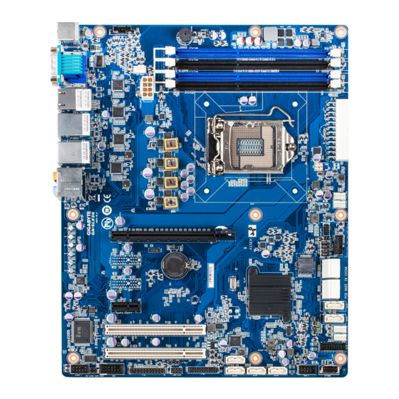
Page 6: Ga-6Lxsg/Ga-6Lxsl Motherboard Layout
GA-6LXSG/GA-6LXSL Motherboard Layout 46 47 - 6 -... - Page 7 Item Code Description HD_AUDIO Audio jacks USB3_LAN1 LAN1 port (top) / USB 3.0 ports (bottom) USB2_LAN2 LAN2 port (top) / USB 2.0 ports (bottom) LAN3_4 LAN ports VGA_COM1 Serial port (top) / VGA port (bottom) USB 2.0 ports (top)/PS/2 connector PS2_USB2 (buttom) PMBUS...
- Page 8 Battery socket PCIE_4 PCI-E x16 slot Intel I210 GbE LAN chipset (GA-6LXSG) U615(I210)/U604(RTL8111F) Realtek RTL8111F GbE LAN chipset (GA-6LXSL) Intel I210 GbE LAN chipset (GA-6LXSG) U617(I210)/U605 (RTL8111F) Realtek RTL8111F GbE LAN chipset (GA-6LXSL) Intel I210 GbE LAN chipset (GA-6LXSG) U619(I210)/U606(RTL8111F)
-
Page 9: Ga-6Lxsg Block Diagram
GA-6LXSG Block Diagram - 9 -... -
Page 10: Ga-6Lxsl Block Diagram
GA-6LXSL Block Diagram - 10 -... -
Page 11: Chapter 1 Hardware Installation
Chapter 1 Hardware Installation Installation Precautions The motherboard contains numerous delicate electronic circuits and components which can become damaged as a result of electrostatic discharge (ESD). Prior to installation, carefully read the user's manual and follow these procedures: • Prior to installation, do not remove or break motherboard S/N (Serial Number) sticker or warranty sticker provided by your dealer. -
Page 12: Product Specifications
Support for DDR3 1333/1600 MHz memory modules Š Support for non-ECC, un-buffered memory modules Š 4 x Intel I210 supports 10/100/1000 Mbps (GA-6LXSG) Š ® 4 x Realtek 8111F-VB supports 10/100/1000 Mbps (GA-6LXSL) Š ® Onboard Build-In Intel H87 Express chipset Š ® Graphics... - Page 13 Back Panel 4 x USB 2.0 ports Š Connectors 2 x USB 3.0 ports Š 1 x PS/2 Keyboard/Mouse port Š 4 x RJ-45 ports Š 1 x COM port Š 1 x VGA port Š 6 x Audio jacks Š...
-
Page 14: Installing The Cpu And Cpu Cooler
Installing the CPU and CPU Cooler Read the following guidelines before you begin to install the CPU: • Make sure that the motherboard supports the CPU. • Always turn off the computer and unplug the power cord from the power outlet before installing the CPU to prevent hardware damage. - Page 15 B. Follow the steps below to correctly install the CPU into the motherboard CPU socket. Before installing the CPU, make sure to turn off the computer and unplug the power cord from the power outlet power plug to prevent any damage to prevent damage to the CPU. Step 1: Step 2: Gently press the CPU socket lever handle down...
-
Page 16: Installing The Cpu Cooler
1-3-2 Installing the CPU Cooler Follow the steps below to correctly install the CPU cooler on the motherboard. (The following procedure uses Intel boxed cooler as the example cooler.) ® Male Push Direction of the Arrow Sign on The Top the Male Push of Female Push Pin... -
Page 17: Installing The Memory
Installing the Memory Read the following guidelines before you begin to install the memory: • Make sure that the motherboard supports the memory. It is recommended that memory of the same capacity, brand, speed, and chips be used. • Always turn off the computer and unplug the power cord from the power outlet before installing the memory to prevent hardware damage. -
Page 18: Installing A Memory
1-4-2 Installing a Memory Before installing a memory module, make sure to turn off the computer and unplug the power cord from the power outlet to prevent damage to the memory module. Be sure to install DDR3 DIMMs on this motherboard. Installation Step: Step 1. -
Page 19: Back Panel Connectors
Back Panel Connectors USB 2.0 Port The USB port supports the USB 2.0 specification. Use this port for USB devices such as a USB key- board/mouse, USB printer, USB flash drive and etc. PS/2 Keyboard/Mouse Port Coonnect a PS/2 keyboard or mouse to this port. Serial Port Connects to serial-based mouse or data processing devices. VGA Port The video in port allows connect to video in, which can also apply to video loop thru function. RJ-45 LAN Port The Gigabit Ethernet LAN port provides Internet connection at up to 1 Gbps data rate. - Page 20 I210/RTL8111F Speed LED: Link/Activity LED: State Description State Description Link Yellow On 1 Gbps data rate Link bet ween system and net work or no Speed LED Activity LED Yellow Blink Identif y 1 Gbps data access rate Blinking Data transmission or receiving is occurring Green On 100 Mbps data rate No data transmission or receiving is occurring...
-
Page 21: Internal Connectors
Internal Connectors 11 12 ATX1 COM1 P12V_AUX1 CPU0_FAN (CPU Fan) SATA_SGP1 SYS_FAN1 (System Fan) F_AUDIO SYS_FAN2 (System Fan) SPDIF_IN1 SYS_FAN3 (System Fan) SPDIF_OUT1 SYS_FAN4 (System Fan) LAN3_ACT PMBUS LAN4_ACT SATA0 SATA1 ME_UPDATE SATA_2_3 CASE_OPEN SATA_4_5 BIOS_RCVR SATA6/7 CLR_CMOS SATA8/9 PCH_ME FP_1 BIOS_PWD BP_1... - Page 22 Read the following guidelines before connecting external devices: • First make sure your devices are compliant with the connectors you wish to connect. • Before installing the devices, be sure to turn off the devices and your computer. Unplug the power cord from the power outlet to prevent damage to the devices.
- Page 23 1/2) ATX1/P12V_AUX1 (2x12 Main Power Connector and 2x4 12V Power Connector) With the use of the power connector, the power supply can supply enough stable power to all the com- ponents on the motherboard. Before connecting the power connector, first make sure the power supply is turned off and all devices are properly installed. The power connector possesses a foolproof design. Connect the power supply cable to the power connector in the correct orientation.
- Page 24 3/4/5/6/7) CPU0_FAN/SYS_FAN1/SYS_FAN2/SYS_FAN3/SYS_FAN4 (CPU Fan/System Fan Headers) The motherboard has a 4-pin CPU fan header (CPU0_FAN), and four 4-pin (SYS_FAN1/SYS_FAN2/ SYS_FAN3/SYS_FAN4) system fan headers. Most fan headers possess a foolproof insertion design. When connecting a fan cable, be sure to connect it in the correct orientation (the black connector wire is the ground wire).
- Page 25 PORT PORT 9/10/11/12/13/14) SATA0/SATA1/SATA_2_3/SATA_4_5/SATA6/SATA7/SATA8/SATA9 (SATA 6Gb/s Connectors) The SATA connectors conform to SATA 6Gb/s standard and are compatible with SATA 3Gb/s and 1.5Gb/s standard. Each SATA connector supports a single SATA device. SATA9 SATA8 SATA7 SATA6 When SATA_DOM0/1 jumper When SATA_DOM0/1 jumper are set to 1-2 pin: are set to 2-3 pin: SATA0...
- Page 26 15) FP_1 (Front Panel Header) Connect the power switch, reset switch, chassis intrusion switch/sensor and system status indicator on the chassis to this header according to the pin assignments below. Note the positive and negative pins before connecting the cables. 23 24 Pin No. Signal Name Definition...
- Page 27 16) BP_1 (HDD Back Plane Board Hearders) Pin No. Definition PCH_THROTTLE_N RresetL_BRB BP_ALED_N BP_LED_G_N 25 26 SMB_BPB1_DATA SMB_BPB1_CLK P_3V3_AUX BP_HDD_TYPE P_3V3_AUX BP_PRESENSE - 27 - Hardware Installation...
- Page 28 17) F_USB3 (USB 3.0 Header) The headers conform to USB 3.0 specification. Each USB header can provide two USB ports via an op- tional USB bracket. For purchasing the optional USB bracket, please contact the local dealer. Pin No. Definition Power IntA_P1_SSRX- IntA_P1_SSRX+ IntA_P1_SSTX- IntA_P1_SSTX+ IntA_P1_D- IntA_P1_D+ IntA_P2_D+ IntA_P2_D- IntA_P2_SSTX+ IntA_P2_SSTX- IntA_P2_SSRX+ IntA_P2_SSRX- Power No Pin 18) F_USB2 (USB 2.0 Header) The headers conform to USB 2.0/1.1 specification. Each USB header can provide two USB ports via an optional USB bracket.
- Page 29 19) COM1 (Serial Port Header) The COM header can provide one serial port via an optional COM port cable. For purchasing the op- tional COM port cable, please contact the local dealer. Pin No. Definition NDCD- NSIN NSOUT NDTR- NDSR- NRTS- NCTS- NRI- No Pin...
- Page 30 21) SATA_SGP1 (SATA SGPIO Header) SGPIO is stands for Serial General Purpose Input/Output which is a 4-signal (or 4-wire) bus used be- tween a Host Bus Adapter (HBA) and a backplane. Out of the 4 signals, 3 are driven by the HBA and 1 is driven by the backplane.
- Page 31 23/24) SPDIF_IN/SPDIF_OUT (SPDIF In and SPDIF Out Header) SPDIF_IN SPDIF_OUT Pin No. Definition SPDIF_IN Pin No. Definition SPDIF_OUT 25/26) LAN3_ACT/LAN4_ACT(LAN3/LAN4 Active LED Header) LAN4_ACT LAN3_ACT Pin No. Definition 3.3V Active - 31 - Hardware Installation...
- Page 32 27) BAT (Battery) The battery provides power to keep the values (such as BIOS configurations, date, and time information) in the CMOS when the computer is turned off. Replace the battery when the battery voltage drops to a low level, or the CMOS values may not be accurate or may be lost. • Always turn off your computer and unplug the power cord before replacing the battery. •...
- Page 33 29) CASE_OPEN (Case open intrusion header) Open: Active chassis intrustion alert. Closed: Normal operation. 30) BIOS_RCVR (BIOS Recovery Jumper) 1-2 Close: Normal operation. (Default setting) 2-3 Close: BIOS recovery mode. - 33 - Hardware Installation...
- Page 34 31) CLR_CMOS (Clearing CMOS Jumper) Use this jumper to clear the CMOS values (e.g. date information and BIOS configurations) and reset the CMOS values to factory defaults. To clear the CMOS values, place a jumper cap on the two pins to temporarily short the two pins or use a metal object like a screwdriver to touch the two pins for a few seconds.
- Page 35 30/31) SATA_DOM0/SATA_DOM1 (SATA port 0 and port 1 DOM Jumpers) CAUTION! • If the SATA DOM power is supplied by the motherboard, set the jumper to pin 1-2. • If the SATA DOM power is supplied by external power, set the jumper to pin 2-3. • If a SATA type hard drive is connected to the motherboard, please ensure the jumper is closed and set to 2-3 pins (Default setting), in order to reduce any risk of hard disk damage.
-
Page 36: Chapter 2 Bios Setup
Chapter 2 BIOS Setup BIOS (Basic Input and Output System) records hardware parameters of the system in the EFI on the motherboard. Its major functions include conducting the Power-On Self-Test (POST) during system startup, saving system parameters and loading operating system, etc. BIOS includes a BIOS Setup program that allows the user to modify basic system configuration settings or to activate certain system features. When the power is turned off, the battery on the motherboard supplies the necessary power to the CMOS to keep the configuration values in the CMOS. - Page 37 Main This setup page includes all the items in standard compatible BIOS. Advanced This setup page includes all the items of AMI BIOS special enhanced features. (ex: Auto detect fan and temperature status, automatically configure hard disk parameters.) Chipset This setup page includes all the submenu options for configuring the function of North Bridge and South Bridge. (ex: Auto detect fan and temperature status, automatically configure hard disk parameters.) Security Change, set, or disable supervisor and user password. Configuration supervisor password allows you to restrict access to the system and BIOS Setup. A supervisor password allows you to make changes in BIOS Setup.
-
Page 38: The Main Menu
The Main Menu Once you enter the BIOS Setup program, the Main Menu (as shown below) appears on the screen. Use arrow keys to move among the items and press <Enter> to accept or enter other sub-menu. Main Menu Help The on-screen description of a highlighted setup option is displayed on the bottom line of the Main Menu. - Page 39 BIOS Information BIOS Version Display version number of the BIOS setup utility. BIOS Build Date and Time Displays the date and time when the BIOS setup utility was created. Processor Information Processor Information CPU Type/Brand String/Frequency/Processor ID/Stepping/Number of Processors/ Microcode Patch Revison Displays the technical specifications for the installed processor.
-
Page 40: Advanced Menu
Advanced Menu The Advanced menu display submenu options for configuring the function of various hardware components. Select a submenu item, then press Enter to access the related submenu screen. BIOS Setup - 40 -... -
Page 41: Acpi Configuration
2-2-1 ACPI Configuration ACPI Settings ACPI Sleep State Select the highest ACPI sleep state the system will enter, when the suspend button is pressed. Options available: Suspend Disabled/S1 only (CPU Stop Clock)/S3 only (Suspend to RAM)/ Both S1 and S3 available for OS to choose from. Default setting is S3 only (Suspend to RAM). - 41 - BIOS Setup... -
Page 42: Trusted Computing (Optional)
2-2-2 Trusted Computing (Optional) Configuration Security Device Support Select Enabled to activate TPM support feature. Options available: Enabled/Disabled. Default setting is Disabled. Current Status Information Display current TPM status information. BIOS Setup - 42 -... -
Page 43: Pci Subsystem Settings
2-2-3 PCI Subsystem Settings PCI Express Slot #1/2 I/O ROM When enabled, This setting will initialize the device expansion ROM for the related PCI-E slot. Options available: Enabled/Disabled. Default setting is Enabled. PCI Slot #1/2 I/O ROM When enabled, This setting will initialize the device expansion ROM for the related PCI slot. Options available: Enabled/Disabled. - Page 44 VGA Palette Snoop Enable/Disable VGA Palette Tegisters Snooping. Options available: Enabled/Disabled. Default setting is Disabled. PERR Generation When this item is set to enabled, PCI bus parity error (PERR) is generated and is routed to NMI. Options available: Enabled/Disabled. Default setting is Disabled. SERR Generation When this item is set to enabled, PCI bus system error (SERR) is generated and is routed to NMI.
-
Page 45: Pci Express Settings
2-2-3-1 PCI Express Settings PCI Express Device Register Settings Relaxed Ordering Enable/DIsable PCI Express Device Relaxed Ordering feature. Options available: Enabled/Disabled. Default setting is Disabled. Extended Tag Wnen this feature is enabled, the system will allow device to use 8-bit Tag field as a requester. Options available: Enabled/Disabled. Default setting is Disabled. No Snoop Enable/Disable PCI Express Device No Snoop option. Options available: Enabled/Disabled. - Page 46 Link Training Retry Define the number of Retry Attempts software wil take to retrain the link if previous training attempt was unsuccessful. Press <+> / <-> keys to increase or decrease the desired values. Link Training Timeout (us) Define the number of Microseconds software will wait before polling 'Link Training' bit in Link Status register. Press <+> / <-> keys to increase or decrease the desired values. Value rang is from 10 to 10000 us.
- Page 47 2-2-4 CPU Configuration - 47 - BIOS Setup...
-
Page 48: Cpu Configuration
CPU Configuration CPU Type/Signature/Processor Family/Microcode Patch/FSB Speed/Max CPU Speed/ Min CPU Speed/ Processor Cores/Intel HT Technology/Intel VT-x Technology/ Intel SMX Technology Displays the technical specifications for the installed processor. 64-bit Display the supported information of installed CPU. EIST Technology Display Intel EIST Technology function support information. CPU C3 state Display the support information of CPU C3 state feature. - Page 49 Intel Virtualization Technology Select whether to enable the Intel Virtualization Technology function. VT allows a single platform to run multiple operating systems in independent partitions. Options available: Enabled/Disabled. Default setting is Enabled. Hardware Prefetcher Select whether to enable the speculative prefetch unit of the processor. Options available: Enabled/Disabled.
- Page 50 Options available: Enabled/Disabled. Default setting is Enabled. Enhanced C1 state Enable/Disable C1E State feature. Options available: Enabled/Disabled. Default setting is Enabled. CPU C3/C6 Report (Note) Allows you to determine whether to let the CPU enter C3/C6 mode in system halt state. When enabled, the CPU core frequency and voltage will be reduced during system halt state to decrease power consumption.
-
Page 51: Sata Configuration
2-2-5 SATA Configuration - 51 - BIOS Setup... - Page 52 SATA Controller(s) Enable/Disable the SATA controller. Options available: Enabled/Disabled. Default setting is Enabled. SATA Mode Selection Select the on chip SATA type. IDE Mode: When set to IDE, the SATA controller disables its RAID and AHCI functions and runs in the IDE emulation mode.
-
Page 53: Software Feature Mask Configuration
2-2-5-1 Software Feature Mask Configuration RAID 0 Enable/Disable RAID 0 feature. Options available: Enabled/Disabled. Default setting is Enabled. RAID 1 Enable/Disable RAID 1 feature. Options available: Enabled/Disabled. Default setting is Enabled. RAID 10 Enable/Disable RAID 10 feature. Options available: Enabled/Disabled. Default setting is Enabled. RAID 5 Enable/Disable RAID 5 feature. - Page 54 Options available: Enabled/Disabled. Default setting is Enabled. LED Locate When this item is enabled, the LED/SGPIO hardware is attached and ping to locate feature is enabled on the OS. Options available: Enabled/Disabled. Default setting is Enabled. IRRT Only on eSATA When this item is enabled, only IRRT volumes can span internal and eSATA drives.
-
Page 55: Info Report Configuration
2-2-6 Info Report Configuration Info Report Configuration Post Report Enable/Disable Post Report support. Options available: Enabled/Disabled. Default setting is Enabled. Delay Time Press <+> / <-> keys to increase or decrease the desired values. Error Message Report Info Error Message Enable/Disable Info Error Message support. Options available: Enabled/Disabled. -
Page 56: Usb Configuration
2-2-7 USB Configuration Legacy USB Support Enables or disables support for legacy USB devices. Options available: Auto/Enabled/Disabled. Default setting is Enabled. USB30. Support Enables/Disable USB3.0 (XHCI) controller support. Options available: Enabled/Disabled. Default setting is Enabled. XHCI Hand-off Enable/Disable XHCI (USB 3.0) Hand-off support. Options available: Enabled/Disabled. -
Page 57: It8732 Super Io Configuration
2-2-8 IT8732 Super IO Configuration - 57 - BIOS Setup... - Page 58 Super IO Chip Display the model name of Super IO chip. Serial Port 1/2 Configuration Serial Port 1/2 When enabled allows you to configure the serial port settings. When set to Disabled, displays no configuration for the serial port. Options available: Enabled/Disabled. Default setting is Enabled. Device Settings Display the Serial Port 1/2 base I/O addressand IRQ. Change Settings Change Serial Port 0/1 device settings. When set to Auto allows the server’s BIOS or OS to select a configuration.
-
Page 59: It8732 Hw Monitor
2-2-9 IT8732 HW Monitor Press Enter to view the Hardware Monitor screen which displays a real-time record of the CPU/system temperature, and fan speed, Items on this window are non-configurable. - 59 - BIOS Setup... -
Page 60: Serial Port Console Redirection
2-2-10 Serial Port Console Redirection BIOS Setup - 60 -... - Page 61 COM1/COM2/Serial Port for Out-of Band Management/Windows Emergency Management Service (EMS) Console Redirection (Note) Select whether to enable console redirection for specified device. Console redirection enables users to manage the system from a remote location. Options available: Enabled/Disabled. Default setting is Disabled. Console Redirection Settings Terminal Type Select a terminal type to be used for console redirection. Options available: VT100/VT100+/ANSI /VT-UTF8.
- Page 62 Stop Bits Stop bits indicate the end of a serial data packet. (A start bit indicates the beginning). The standard setting is 1 stop bit. Communication with slow devices may require more than 1 stop bit. Options available: 1/2. Flow Control Flow control can prevent data loss from buffer overflow. When sending data, if the receiving buffers are full, a 'stop' signal can be sent to stop the data flow. Once the buffers are empty, a 'start' signal can be sent to re-start the flow. Hardware flow control uses two wires to send start/stop signals.
-
Page 63: Network Stack
2-2-11 Network Stack Network stack Enable/Disable UEFI network stack. Options available: Enabled/DIsabled. Default setting is Disabled. Ipv4 PXE Support (Note) Enable/Disable Ipv4 PXE feature. Options available: Enabled/DIsabled. Default setting is Enabled. Ipv6 PXE Support (Note) Enable/Disable Ipv6 PXE feature. Options available: Enabled/DIsabled. Default setting is Enabled. (Note) This item appears when Network Stack is set to Enabled. -
Page 64: Intel(R) Anti-Theft Technology Configuration
2-2-12 Intel(R) Anti-Theft Technology Configuration Intel(R) Anti-Theft Technology Configuration Intel(R) Anti-Theft Technology Enable/Disable Intel(R) Anti-Theft Technology Configuration. Options available: Enabled/DIsabled. Default setting is Enabled. Enter Intel (R) AT Suspended Mode This item is not configurable. BIOS Setup - 64 -... -
Page 65: Switchable Graphics
2-2-13 Switchable Graphics Items on this window are non-configurable. - 65 - BIOS Setup... -
Page 66: Intel(R) Rapid Start Technology
2-2-14 Intel(R) Rapid Start Technology Intel(R) Rapid Start Technology Enable/Disable Intel(R) Rapid Startt Technology. Options available: Enabled/DIsabled. Default setting is Enabled. Entery on S3 RTC Wake Enable/Disable Enterr on S3 RTC Wake. Options available: Enabled/DIsabled. Default setting is Enabled. Enter After Define S3 RTC Wake time. Press <+> / <-> keys to increase or decrease the desired values. -
Page 67: Pch-Fw Configuration
2-2-15 PCH-FW Configuration - 67 - BIOS Setup... - Page 68 ME FW Version Display the ME firmware version information. ME Firmware Mode Display the ME firmware mode. ME Firmware Type Display the ME firmware type. ME Firmware SKU Display the ME firmware SKU. MEBx Type Configure the MEBx (Intel® Management Engine BIOS Extention) type . Options available: None. Default setting is None. MEDS BIOS Status Code Options available: Enabled/DIsabled. Default setting is Disabled. Firmware Update Configuration Me FW Image Re-Flash Options available: Enabled/DIsabled.
-
Page 69: Intel(R) Smart Connect Technology
2-2-16 Intel(R) Smart Connect Technology ISCT Support Enable/Disable Intel(R) Rapid Smart Connect Technology support function. Options available: Enabled/DIsabled. Default setting is Disabled. - 69 - BIOS Setup... -
Page 70: Smart Settings
2-2-17 Smart Settings Smart Settings SMART Self Test Run SMART Self Test on all HDDs during POST. Options available: Enabled/DIsabled. Default setting is Disabled. BIOS Setup - 70 -... -
Page 71: Amt Configuration
2-2-18 AMT Configuration Intel AMT Enable/Disable Intel(R) Active Management Technology BIOS Extension. Options available: Enabled/DIsabled. Default setting is Enabled. BIOS Hotkey Pressed Options available: Enabled/DIsabled. Default setting is Disabled. MEBx Selection Screen Options available: Enabled/DIsabled. Default setting is Disabled. Hide Un-Configure ME Confirmation Prompt Hide Un-Configure ME without password confirmation prompt. Options available: Enabled/DIsabled. - Page 72 Active Remote Assistance Process Options available: Enabled/DIsabled. Default setting is Disabled. USB Configure Options available: Enabled/DIsabled. Default setting is Enabled. PET Progress Options available: Enabled/DIsabled. Default setting is Enabled. AMT CRIA Timeout Press <+> / <-> keys to increase or decrease the desired values. WatchDog Options available: Enabled/DIsabled.
-
Page 73: Acoustic Management Configuration
2-2-19 Acoustic Management Configuration Acoustic Management Configuration Automatic Acoustic Management Enable/Disable Automatic Acoustic Management. Options available: Enabled/DIsabled. Default setting is Disabled. - 73 - BIOS Setup... -
Page 74: Chipset Menu
Chipset Menu The Chipset menu display submenu options for configuring the function of North Bridge and South Bridge. Select a submenu item, then press Enter to access the related submenu screen. BIOS Setup - 74 -... -
Page 75: System Agent (Sa)Configuration
2-3-1 System Agent (SA)Configuration System Agent Bridge Name Display the System Agent (SA) Bridge Name. System Agent RC Version Display the version number of System Agent RC. VT-d Capability Display the VT-d support information. VT-d Enable/Disable Intel Virtualization Technology for Directed I/O (VT-d) feature. Options available: Enabled/DIsabled. -
Page 76: Graphic Configuration
2-3-1-1 Graphic Configuration Graphic Configuration Primary PEG Select PEG0/PEG1/PEG2/PEG3 Graphic device should be Primary PEG. Options available: Auto/PEG0/PEG1/PEG2/PEG3. Default setting is Auto. Primary PCIE Configure the Primary display device. Options available: Auto/PCIE_1/PCIE_2/PCIE_3/Onboard VGA. Default setting is Auto. Internal Graphics Configure internal graphic function. Options available: Auto/Enabled/Disabled. Default setting is Auto. Aperture Size Select aperture Size. - Page 77 DVMT Pre-Allocated Select DVMT 5.0 Pre-Allocated (Fixed) Graphics Memory Size is used by the internal Graphics Device. Options available: 32M/64M/96M/128M/160M/192M/224M/256M/288M/320M/352M/384M/416M/448M/4 80M/512M/1024M. Default setting is 32M. DVMT Total Gfx Mem Select DVMT 5.0 Total Graphic Memory Size is used by the internal Graphics Device. Options available: 128M/256M/Max.
-
Page 78: Nb Pcie Configuration
2-3-1-2 NB PCIe Configuration NB PCIe Configuration PEG0 Display PEG0 configuration information. PEG0 - Gen X Configure PEG0 B0:D1:F0 Gen1-Gen3. Options available: Auto/Gen1/Gen2/Gen3. Default setting is Auto. PEG1 Display PEG1 configuration information. PEG1 - Gen X Configure PEG1 B0:D1:F1 Gen1-Gen3. Options available: Auto/Gen1/Gen2/Gen3. Default setting is Auto. PEG2 Display PEG2 configuration information. PEG2 - Gen X Configure PEG2 B0:D1:F2 Gen1-Gen3. Options available: Auto/Gen1/Gen2/Gen3. Default setting is Auto. Run-time C7 Allowed Configure Run-time C7 feature. - Page 79 Detect Non-Compliance Device Detect Non-Compliance PCI Express Device in PEG. Options available: Enabled/Disabled. Default setting is Disabled. Program PCIe ASPM after OpROM Enable/Disable Program PCIe ASPM after OpROM. Options available: Enabled/Disabled. Default setting is Disabled. PEG0 De-emphasis Control PEG0:Configure the De-emphasis control on PEG. Options available: Options available: -6 dB/-3.5 dB. Default setting is -3.5 dB. PEG1 De-emphasis Control PEG1:Configure the De-emphasis control on PEG.
-
Page 80: Memory Configuration
2-3-1-3 Memory Configuration Memory Information Memory RC Version Display version number of installed memeory. Memory Frequency Display the frequency information of installed memory. Total Memory Determines how much total memory is present during the POST. Memory Voltage Display the voltage information of installed memory. DIMM Information: DDR3_P0_A0/DDR3_P0_A1/DDR3_P0_B0/DDR3_P0_B1 Status The size of memory installed on each of the DDR3 slots. - Page 81 Memory Frequency Limiter Maximum Memory Frequency Selections in Mhz. Options available: Auto/1067/1333/1600/1867/2133/2400/2667. Default setting is Auto. ECC Support Enable/Disable ECC support. Options available: Enabled/Disabled. Default setting is Enabled. Max TOLUD Maximum Value of TOLUD. Dynamic assignment would adjust TOLUD automatically based on largest MMIO length of installed graphic controller.
-
Page 82: Pch-Io Configuration
2-3-2 PCH-IO Configuration Intel PCH RC Version/Intel PCH SKU/Intel PCH Rev ID Information Displays the RC version, SKU and Reverison ID information of PCH. PCI Express Configuration Press [Enter] for configuration of advanced items. USB Configuration Press [Enter] for configuration of advanced items. DeepSx Power Policies Configure the DeepSx Mode configuration. Options available: Disabled/Enabled in S5/Enabled in S4-S5. Default setting is Disabled. GP27 Wake From DeepSx Wake from DeepSx by the assertion of GP27 pin. - Page 83 SLP_S4 Assertion Width Select a minimum assertion width of the SLP_S4# signal. Options available: 1-2 Seconds/2-3 Seconds/3-4 Seconds/4-5 Seconds. Default setting is 4-5 Seconds. Restore AC Power Loss This option provides user to set the mode of operation if an AC / power loss occurs. Power On: System power state when AC cord is re-plugged.
-
Page 84: Pci Express Configuration
2-3-2-1 PCI Express Configuration PCI Express Clock Gating Enable/Disable PCI Express Clock Gating for each root port. Options available: Enabled/Disabled. Default setting is Enabled. DMI Link ASPM Control The control of Active State Power Management on both NB side and SB side of the DMI Link. Options available: Enabled/Disabled. -
Page 85: Usb Configuration
2-3-2-2 USB Configuration USB Configuration USB Precondition Precondition work on USB host controller and root ports for faster enumeration. Options available: Enabled/Disabled. Default setting is Disabled. XHCI Mode Mode of operation of xHCI controller. Options available: Smart Auto/Auto/Enabled/Disabled/Manual. Default setting is Smart Auto. BTCG Options available: Enabled/Disabled. -
Page 86: Security Menu
Security Menu The Security menu allows you to safeguard and protect the system from unauthorized use by setting up access passwords. There are two types of passwords that you can set: • Administrator Password Entering this password will allow the user to access and change all settings in the Setup Utility. •... -
Page 87: Secure Boot Menu
2-4-1 Secure Boot menu The Secure Boot Menu is applicable when your device is installed the Windows 8 operatin system. ® Secure Mode Display the System secure mode state. Secure Boot Display the status of Secure Boot. Secure Boot Support Enable/Disable Secure Boot function. -
Page 88: Key Management
2-4-1-1 Key Management Key Management This item appears only when the Secure Boot Mode is set to Custom. Factory Default Key Provisioning Force the system to Setup Mode. This will clear all Secure Boot Variables such as Platform Key (PK), Key-exchange Key (KEK), Authorized Signature Database (db), and Forbidden Signaures Database (dbx). - Page 89 Set new KEK Press [Enter] to configure a new KEK. Append Var to KEK Press [Enter] to load additional KEK from a storage devices for an additional db and dbx management. Authorized Signature Database (DB) Display the status of Authorized Signature Database. Delete DB Press [Enter] to delete the db from your system. Set new DB Press [Enter] to configure a new db.
-
Page 90: Boot Menu
Boot Menu The Boot menu allows you to set the drive priority during system boot-up. BIOS setup will display an error message if the legacy drive(s) specified is not bootable. Boot Configuration Setup Prompt Timeout Number of seconds to wait for setup activation key. 65535(0xFFFF) means indefinite waiting." Press the numberic keys to input the desired value. Bootup NumLock State Enable or Disable Bootup NumLock function. Options available: On/Off. - Page 91 Hard drive. Network device. Removable device. Hard Drive BBS Priorities Press Enter to configure the boot priority. Network Device BBS Priorities Press Enter to configure the boot priority. CSM16 Parameters Press [Enter] for configuration of advanced items. CSM parameters Press [Enter] for configuration of advanced items. BIOS Setup - 91 -...
-
Page 92: Csm16 Parameters
2-5-1 CSM16 Parameters CSM16 Module Version Display CSM Module version information. Gate20 Active Upon Request: GA20 can be disabled using BIOS services. Always: Do not allow disabling GA20; this option is useful when any RT code is executed above 1MB. Options available: Upon Request/Always. -
Page 93: Csm Parameters
2-5-2 CSM Parameters CSM parameters Press Enter to configure the advanced items. CSM (Compatibility Support Module) Launch Enable/Disable Compatibility Support Module (CSM) launch. Options available: Enabled/Disabled. Default setting is Enabled. • The following five items appears and configurable when the Launch CSM is set to Enabled. • If the Launch CSM is set to Disabled, the following five items will not be able to support Legacy mode. - Page 94 Other PCI device ROM priority For PCI devices other than Network, Mass storage or Video device, defines which OpROM to launch. Options available: UEFI OpROM/Legacy OpROM. Default setting is UEFI OpROM. BIOS Setup - 94 -...
-
Page 95: Exit Menu
Exit Menu The Exit menu displays the various options to quit from the BIOS setup. Highlight any of the exit options then press Enter. Save Changes and Exit Saves changes made and close the BIOS setup. Options available: Yes/No. Discard Changes and Exit Discards changes made and close the BIOS setup. -
Page 96: Bios Beep Codes
BIOS Beep Codes # of Beeps Description Invalid password Recovery started S3 Resume failed DXEIPL was not found No Console Input/Output Devices are found Flash update is failed BIOS Setup - 96 -... -
Page 97: Bios Recovery Instruction
BIOS Recovery Instruction The system has an embedded recovery technique. In the event that the BIOS becomes corrupt the boot block can be used to restore the BIOS to a working state. To restore your BIOS, please follow the instructions listed below: Recovery Instruction: Change xxx.ROM to amiboot.rom. -
Page 98: Chapter 3 Appendix
Chapter 3 Appendix Regulatory Statements Regulatory Notices This document must not be copied without our written permission, and the contents there of must not be imparted to a third party nor be used for any unauthorized purpose. Contravention will be prosecuted. We believe that the information contained herein was accurate in all respects at the time of printing. - Page 99 Finally, we suggest that you practice other environmentally friendly actions by understanding and using the energy-saving features of this product (where applicable), recycling the inner and outer packaging (including shipping containers) this product was delivered in, and by disposing of or recycling used batteries properly. With your help, we can reduce the amount of natural resources needed to produce electrical and electronic equipment, minimize the use of landfills for the disposal of "end of life" products, and generally improve our quality of life by ensuring that potentially hazardous substances are not released into the environment and...
Need help?
Do you have a question about the GA-6LXSL and is the answer not in the manual?
Questions and answers