Table of Contents
Advertisement
Advertisement
Table of Contents

Related Manuals for AVANT LEGUAN 225


Summary of Contents for AVANT LEGUAN 225
- Page 1 Operator and service manual...
- Page 3 LEGUAN 225 OPERATOR AND SERVICE MANUAL This operator and service manual is valid on serial numbers: 0080100 -> Version history Date Change 22.11.2022 Original document 15.12.2022 Pictures updated 13.1.2023 Drive motor gear oil change 10.2.2023 Technical specification and decals updated 14.4.2023...
-
Page 4: Table Of Contents
Table of contents INTRODUCTION AND WARRANTY CONDITIONS Introduction Display of safety instructions Warranty conditions Example of the EC declaration of conformity GENERAL INFORMATION Technical specifications Main dimensions and outreach diagram Signs and decals SAFETY INSTRUCTIONS Before starting operation Risk of tipping over Risk of falling Risk of collision Risk of electric shock... - Page 5 EMERGENCY LOWERING AND EMERGENCY BYPASS Emergency lowering Backup operation Platform load control and platform emergency stop button override Safety function override button TRANSPORTATION SERVICE, MAINTENANCE AND INSPECTION REGULATIONS General instructions SERVICE INSTRUCTIONS Service and checks, maintenance schedule 9.1.1 General service info 9.1.2 Major inspection 9.1.3...
-
Page 6: Introduction And Warranty Conditions
INTRODUCTION AND WARRANTY CONDITIONS Introduction LEGUAN LIFTS wants to thank you for purchasing this Leguan access platform. It is the result of Leguan’s long experience in design and manufacturing of access equipment. We ask you that you read and understand the contexts of this manual completely before operating the access platform. -
Page 7: Warranty Conditions
Warranty conditions This product is warranted for a period of twenty-four (24) months without hour limit. In the event a fault occurs which is attributable to manufacturing or assembly defect, contact the dealer without delay. Warranty covers manufacturing and material defects. All warranty obligations end when the warranty period ends. -
Page 8: Example Of The Ec Declaration Of Conformity
Example of the EC declaration of conformity... -
Page 9: General Information
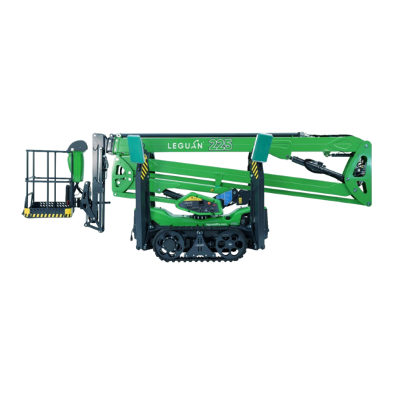
GENERAL INFORMATION LEGUAN 225 is a self-propelled Mobile Elevating Work Platform – commonly called an access platform – designed for indoor and outdoor use. Access platforms are designed for the lifting of persons and their equipment only. Using an access platform as a crane is prohibited. - Page 10 Figure 1. Main parts...
-
Page 11: Technical Specifications
Technical specifications Working height 22,5 m Max. platform height 20,5 m Max. outreach @ 250 kg 9,1 m Max. outreach @ 120 kg 11,2 m Max. platform rated load 250 kg Max. wind speed 12,5 m/s Max. manual force 400 N Transport length 6,03 m Transport length without platform... -
Page 12: Main Dimensions And Outreach Diagram
Main dimensions and outreach diagram Figure 2. Required space for outriggers in widest position Figure 3. Main dimensions from side Figure 4. Main dimensions from behind... - Page 13 Figure 5. Outreach diagram...
-
Page 14: Signs And Decals
Signs and decals 2. Tie down points 1. Outrigger force and lifting points 3. Residual current device 4. Lower control panel 5. Emergency procedures 6. Daily inspection and general instructions 8. Crushing of hands hazard 7. Radio controlled (option) - Page 15 9. Type plate 10. Platform control panel 11. Maximum rated load 12. Distance from energized electric wires 13. Operator manual...
- Page 16 Figure 6. Signs and decals...
-
Page 17: Safety Instructions
SAFETY INSTRUCTIONS The operator must know and follow all safety instructions. The operator must receive sufficient instructions in order to be able to use the lift correctly and safely. This Operators Manual must always be kept in the box on the platform. -
Page 18: Risk Of Tipping Over
In order to ensure the safe operation of this access platform the manufacturer has conducted approved tests for the LEGUAN 225 in accordance with the standard EN 280:2022 static stability test in accordance with paragraph 5.1.4.2.1 and dynamic overload test in accordance with paragraph 5.1.4.3. -
Page 19: Risk Of Collision
Risk of collision Collision Hazard! Select the drive speed so that it is safe in regard to the ground conditions. The operator must follow all regulations concerning the use of safety equipment on the work site. When operating the lift, beware that visibility may be limited and trapping hazard. Make sure that there are no overhead obstacles on the work site that could prohibit lifting of the platform, or objects that might cause a collision. -
Page 20: Risk Of Explosion/Fire
Risk of explosion/fire Explosion Hazard! It is not allowed to start the combustion engine / electric motor in a place where one can smell LPG, petrol, solvent or other flammable substance. Do not fill with fuel when the engine is running. Charge the battery only in places with sufficient ventilation, where there is no open fire or no works which could cause spark emissions (like welding). -
Page 21: Safety Instructions For Drive Control
Safety instructions for drive control 1. Do not exceed maximum inclination for drive. 2. Make sure the driving surface is solid. 3. Fasten tools and other materials to prevent them falling. 4. Wear safety harnesses and keep them fastened whenever operating the machine. 3.10 Defining the gradient of the slope Measure the slope with a digital inclinometer or do as follows. -
Page 22: Controls And Switches
CONTROLS AND SWITCHES Controls in platform Figure 7. Platform control panel 1. Diesel engine and electric motor start and stop buttons 2. Engine/motor running light 3. Automatic leveling buttons 4. Automatic leveling indication light (blinking) / boom operation allowed (continuously on) 5. -
Page 23: Platform Overload Indicator Light
4.1.1 Platform overload indicator light Tip-over Hazard! Never overload the platform! This access platform is equipped with automatic platform overload system which prevents all boom movements in case the 250 kg rated load is exceeded. Should this happen, there is an audible warning signal and an indicator light up at the control panel (figure 7 (14)). -
Page 24: Inclination Indicator Light
Fault light BLINKS frequently: Can-bus connection has been lost to the upper control panel. Use emergency override system (see 6.4) to return booms back to transport position, stop working with the equipment and contact your local authorized Leguan service workshop. Possible errors and faults can be diagnosed with the display which is located at the lower control panel. -
Page 25: Low Fuel Indicator Light
4.1.7 Low fuel indicator light Low fuel level indicator light (figure 7 (19)) will be lit when there is approximately 4 liters of fuel left in the tank. It will be enough for approximately one hour of constant operation depending on the load on the engine. Fuel tank capacity is 19 liters. -
Page 26: Wireless Remote Control (Option)
Wireless remote control (option) This access platform can be equipped with wireless remote control. The remote controller can be used to operate outriggers and drive functions. The remote controller, spare battery and battery charger are located inside the storage enclosure on the pedestal underneath the 2 lower boom. -
Page 27: 230 V Connection And Switches
230 V connection and switches Leguan 225 can be powered by an electric motor. The motor must be connected to a 230 V / 50 Hz / 16 A outlet. Connections and switches pictured below. 1. 230 V / 50 Hz / 16 A connection lead 2. -
Page 28: Operation
OPERATION An access platform is destined for lifting of persons and their equipment only. It is not allowed to use an access platform as a crane. It is the operator’s responsibility to understand and follow all operating and safety instructions. 1. -
Page 29: Start-Stop Function
5.1.3 Start-stop function The access platform is equipped with automatic start-stop function. The combustion engine rpm is lowered to idle and electric motor is stopped when there aren’t any movements done with the machine. When the engine is idling, the engine run light between the start/stop buttons is blinking. The engine/motor will wake up from idle automatically when movements are done again. -
Page 30: Features Of Tracked Access Platform
5.3.1 Features of tracked access platform An access platform with skid steer chassis on crawler track offers many advantages. However, certain things regarding working and working environment must be taken into account. In order to achieve the maximum lifespan for the rubber tracks and the crawler track chassis, follow the instructions below. The lifespan of the track system of an access platform on rubber tracks is heavily dependent on the working environment and the way of working. -
Page 31: Operation Of The Outriggers
Operation of the outriggers Tip-over Hazard! Booms must not be operated without properly deployed outriggers! The outriggers must be deployed, and the chassis of the access platform must be levelled before any boom operations. The chassis can be levelled by either using automatic levelling function or controlling individual outriggers manually. -
Page 32: Outrigger Manual Drive
5.4.2 Outrigger manual drive 1. Select platform controls. 2. Start electric motor or combustion engine. 3. Turn and hold the mode selection switch to chassis control position (figure 7, switch 7). 4. Select the desired outrigger(s) to be operated by moving the left side joystick to the direction of the outrigger(s) and move the outrigger(s) by pressing the buttons on top of the joystick (left-hand side button moves the outriggers down and right-hand side button moves them up). -
Page 33: Home Function
The platform self-leveling system keeps the platform leveled automatically. If the platform tilting needs to be operated from platform controls, press the platform tilting button (figure 7, button 8) and move the right-hand side joystick forward/backward to tilt the platform up/down. Operate the platform tilting carefully, especially when the booms are up. -
Page 34: Remote Control (Option)
Remote control (option) 1. Select remote control by turning the key switch (figure 8 (1)) to remote control position and take the remote controller out of the storage enclosure (4.3). 2. Release the emergency stop button on the remote controller (figure 10 (1)). 3. -
Page 35: Additional Instructions For Winter Use
Additional instructions for winter use The minimum allowed operating temperature for the access platform is -20 °C. Do the following actions during winter time: Check that the limit switches are free from snow, ice and dirt. If the ambient temperature is below +2 °C / 36 °F, it is recommended to use a separate engine heater (option). -
Page 36: Emergency Lowering And Emergency Bypass
EMERGENCY LOWERING AND EMERGENCY BYPASS Tip-over Hazard! Emergency lowering and emergency bypass must only be used in emergency and fault situations with extreme caution! If the operating power supply cuts off (fuel running out, power outage or damage to the extension cord) the booms can be lowered using one of the following backup systems. -
Page 37: Platform Load Control And Platform Emergency Stop Button Override
Backup operation of booms: 1. Make sure that platform control is the active control position. 2. Turn off the combustion engine / electric motor. 3. Turn and hold the mode selection switch (between joysticks, figure 7, switch 7) to boom position (right-hand side). -
Page 38: Safety Function Override Button
Safety function override button Tip-over Hazard! For possible emergency situations the access platform is equipped with a safety function override button (figure 13 (B)). It enables the operation of drive, outrigger and boom functions in fault situations. The function can for example used in a situation where a sensor has broken, and the machine must be moved to a safe location to be repaired. -
Page 39: Transportation
TRANSPORTATION Before transportation lower the booms down to transport position and lift the outriggers completely up. Transporting of the access platform is allowed in its transport position only. No persons or materials are allowed to be transported on the platform. It is not allowed to tie down the machine so that the ropes go over the booms. -
Page 40: Service, Maintenance And Inspection Regulations
SERVICE, MAINTENANCE AND INSPECTION REGULATIONS All inspections must be done by following local laws and regulations. The access platform must be the inspected once a year (local laws / regulations may require more frequent inspections). The access platform must also be inspected to an adequate extent if it has been damaged and its strength may have been compromised. -
Page 41: Service Instructions
SERVICE INSTRUCTIONS Service and checks, maintenance schedule CH = Check CL = Clean R = Replace *See engine manufacturer’s manual First 100 h 200 h 400 h 1000 h Operation service Daily Monthly 120 mos. 50 h 6 mos. 12 mos. 24 mos. -
Page 42: General Service Info
9.1.1 General service info Hydraulic oil Mobil UNIVIS N 32 Hydraulic system oil Complete system: 55 liters volume Oil change volume: 35 liters Fuel tank volume 19 liters (Diesel) Engine oil See the engine manufacturer’s manual Drive motor gear oil SAE 90~140 (API) and GL-3~GL4 (oil), 0,6 liters for each drive motor Grease Lithium NLGI 2 grease (not MoS2) -
Page 43: Inspection Of Mechanical Structures, Hydraulic And Electric Systems
Figure 16. Track tightness adjustment To inspect the tightness of the tracks: Raise the access platform off the ground using the outriggers. The tracks should be off the ground minimum 5 cm. The tightness is correct if the gap between the track and the track frame is the same from end to end (marked with red lines in figure 16). -
Page 44: Telescope Boom
Telescope boom The tightness of the chains on the telescope boom must be inspected daily. The indicator plate must be within the marks on the steel cover below it on both sides of the boom. Figure 17. Telescope chain tightness indicators Figure 18. -
Page 45: Greasing
Greasing Greasing of the machine is of utmost importance to prevent wear in joints. Most of the joints are service free – however the slew ring must be greased in accordance with the maintenance schedule, using grease that contains EP (extreme pressure) additive. Articulation bearings in all hydraulic cylinders and outrigger plate position pins must be greased in accordance with the maintenance schedule. -
Page 46: Greasing Of The Slew Ring
9.5.2 Greasing of the slew ring The slew ring of the access platform must be greased monthly. It is important to notice that the slew ring has four (4) separate greasing points (figure 20) which all must be greased individually. There is a pressure relief screw (figure 21) at the opposite side of the worm gear of the slew ring which should be opened when greasing the slew ring to avoid the seal from coming off. -
Page 47: Greasing The Telescope Boom Chain Pulley And Inspection Of The Chain
9.5.3 Greasing the telescope boom chain pulley and inspection of the chain A pair of leaf chains is used for telescope boom movement. The pulley wheels must be greasing monthly. Figure 23. Telescope chain pulley wheel Figure 22. Telescope chain pulley wheel greasing points at the lower and upper greasing point at the work platform end boom linkage piece end... -
Page 48: Handling Of Fuel And Refueling
Handling of fuel and refueling Check fuel level and refuel if necessary (fuel tank cap, figure 25 (1)). There is a Kubota diesel engine on the access platform. Use DIESEL fuel only. Use of other fuels is not allowed. See engine manufacturers manual for more information. -
Page 49: Hydraulic Oil Level
Hydraulic oil level Hydraulic oil level can be checked with the dipstick in the filter cap (figure 26 (1)). Oil level should be at the upper mark in the dipstick when the access platform is in transport position (booms down and outriggers completely up). -
Page 50: Diagnostics And Checking The Error Codes
9.11 Diagnostics and checking the error codes The access platform always performs an automatic diagnostic test when the main switch is turned on and the emergency stop button is released. If there are any errors in the check it is informed with a symbol on the first “Home”... -
Page 51: Outrigger Set Up Control
9.12 Outrigger set up control Check the outrigger set up control always before operating the access platform. The spring-loaded pins holding the outrigger plates should move freely. If the pin is stuck, it must be repaired before continuing the operation. When an outrigger is off the ground, the yellow indicator light on the outrigger inductive switch should be active. -
Page 52: Overload Control Components
9.13 Overload control components Tip-over hazard! Overload control has been set to correct values at the factory and its strictly forbidden to change its settings. NEVER OVERLOAD THE ACCESS PLATFORM! The overload control mechanism is located between the work platform and the platform support (figure 35). -
Page 53: Access Platform Position Monitoring
9.14 Access platform position monitoring There are four (4) position sensors on the access platform. One of the sensors is inside the lower control panel which measures the inclination of the chassis. Three other sensors are located in the boom structure. One in the lower boom at the upper end of the cylinder (figure 37), one inside the upper boom under the service hatch (figure 38) and one in the jib boom at the lower end of the cylinder underneath the protective cover (figure 39). -
Page 54: Boom Movement Speeds
Figure 39. Jib boom position sensor These sensors measure the angle of the booms and the length of the telescope boom. The boom transport position is also measured by these sensors. All position sensors are calibrated at the factory and normally there shouldn’t any need to change their calibration. -
Page 55: Testing Of Safety Valves
9.16 Testing of safety valves The safety valves of the access platform must be checked yearly. The lifetime of the safety valves is 30 years after which they must be replaced. There is an internal diagnostic test on the access platform for testing the valves. -
Page 56: Service Reminder
9.17 Service reminder There is a service reminder on the display of the lower control panel. When the next service is getting closer, there will be a symbol (figure 42) showing that on the first “Home page” when the main switch is activated. The hour reading next to the symbol tells the operating time until the next service. -
Page 57: Fuses
9.18 Fuses The fuses of the machine can be found inside the lower control box (figure 44). Do not exceed the original fuse size! 1. Fuses for the control devices, voltage when the main switch is activated 2. Fuses for control devices, voltage always even when main switch is turned off 3. -
Page 58: Battery Handling
9.20 Battery handling Battery contains corrosive sulfuric acid – handle the battery with care. When handling the battery wear protective clothing and eyewear. Avoid contact with clothes or skin; if electrolyte gets on your skin or clothes flush with a lot of water. In case of contact with eyes, flush with a lot of water for at least 15 minutes and call a doctor immediately. -
Page 59: Repair Instructions
REPAIR INSTRUCTIONS 10.1 Welding Risk of failing structure! It is not allowed to change the construction and structure of this access platform without a written permission from the manufacturer. All load carrying steel parts are manufactured from S650MC (EN 10149-2), S420MC EN10149 sheet and S355J2H EN10219 tubular pipe. -
Page 60: Instructions For Temporary Storage
INSTRUCTIONS FOR TEMPORARY STORAGE The cable of the + pole of the battery should be disconnected if the access platform is being stored for a period longer that one month. The access platform shall be covered and, if possible, stored inside or under a roof in a place where unauthorized persons don’t have access. -
Page 61: Instructions For Disposing The Access Platform
INSTRUCTIONS FOR DISPOSING THE ACCESS PLATFORM When the access platforms lifecycle comes to an end, it has to be dissembled and disposed of in an environmentally friendly way. Battery and other electronic components should be recycled or disposed of according to local regulations. -
Page 62: Troubleshooting
TROUBLESHOOTING Following table shows possible failures and malfunctions of the access platform and the ways how to repair them. ISSUE REASON CORRECTIVE ACTION Motor will not start when the start Emergency stop button is pressed Release all emergency stop button is pressed. down. - Page 63 ISSUE REASON CORRECTIVE ACTION Electric motor stops suddenly Power outage. Lower the booms by using the during operation. emergency lowering. Check that there is current in mains. Emergency stop button is active. Release all emergency stop buttons. Electric motor thermal overload Wait for approx.
- Page 64 ISSUE REASON CORRECTIVE ACTION Platform tilts backward by itself Air in hydraulic system. Start the combustion engine / when booms are down on electric motor, drive the platform transport supports. to extreme end positions. If this doesn’t help, do the air bleeding of the platform self levelling system (there are bleeding screws in the self levelling cylinders).
- Page 65 ISSUE REASON CORRECTIVE ACTION Booms in transport position, the Telescope boom not completely or Make sure all booms are in green transport support light is not booms not properly in transport transport position including the on and the fault light is on. position.
-
Page 66: Performed Service
PERFORMED SERVICE It is advisable to write down all service operations that are included in the periodical service. All services that have been made during the warranty period must be noted on the list below, otherwise the manufacturer’s warranty will void. The service operations mentioned in the maintenance schedule on chapter 9.1 shall be noted as follows: First Service (50 hours), 100 hour service, 200 hour / 1 Year service etc.
Need help?
Do you have a question about the LEGUAN 225 and is the answer not in the manual?
Questions and answers