Table of Contents
Advertisement
Quick Links
Operation Manual & Installation
Underceiling
Aircondtioner
Thank you for purchasing our product, please keep and read this manual carefully before
you install.
Engineered for comfort
Engineered for comfort
Model
GS-UNC18ID-INV/1P
GS-UNC24ID-INV/1P
GS-UNC36IDINV/1P
GS-UNC48ID-INV/3P
GS-UNC60ID-INV/3P
Advertisement
Chapters
Table of Contents
Troubleshooting

Related Manuals for SIRAIR GS-UNC18ID-INV/1P


Summary of Contents for SIRAIR GS-UNC18ID-INV/1P
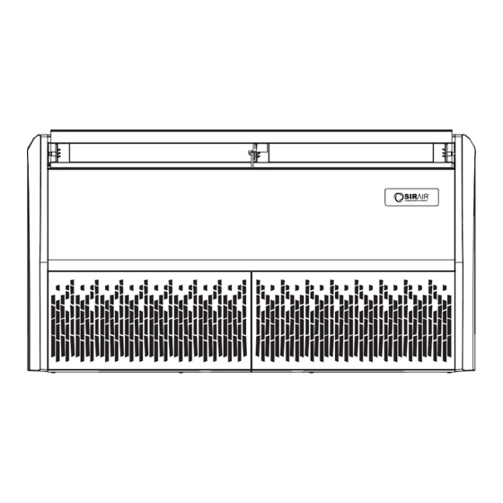
- Page 1 Engineered for comfort Operation Manual & Installation Underceiling Aircondtioner Model Engineered for comfort GS-UNC18ID-INV/1P GS-UNC24ID-INV/1P GS-UNC36IDINV/1P GS-UNC48ID-INV/3P GS-UNC60ID-INV/3P Thank you for purchasing our product, please keep and read this manual carefully before you install.
-
Page 2: Table Of Contents
Technical Manual Floor & Ceiling 1.Features ..................82 2. Specifications ................85 3.Dimensions ..................89 4.Service Space ................90 5.Wiring Diagrams ................91 6.Capacity Table ................95 7.Electric Characteristics ..............99 8. Exploded View ................100 9.Accessories ................. 106 10.The Specification of Power ............107 11.Field Wiring ................ -
Page 3: Features
Technical Manual 1 Features 1. Flexible installation, ceiling suspended and floor standing. 2. Adopting centrifugal fans, higher ESP and longer air flow distance. 3. Two way auto-swing function, built-in two louver motor, vertical and horizontal air-flow adjustment. - Page 4 Technical Manual 4. Washable air filter 5. LED display optional. 6. New upper and lower buckle type wheel case, the upper plastic wheel case can be removed alone, which is convenient adjust the wheel motor. 7. Water pump optional, pumping head is up to 1200mm. 8.
- Page 5 Technical Manual 10. Standard for wireless controller; option for wired controller Standard Optional...
-
Page 6: Specifications
Technical Manual 2 Specifications Model GS-UNC18ID-INV/1P GS-UNC24ID-INV/1P Indoor unit code 821039700060 821023700035 Indoor power supply V/Ph/Hz 220~240/1/50 220~240/1/50 Btu/h 18000 24000 Capacity Cooling Power input 2.26 Ratedcurrent 10.6 Btu/h 18000 24000 Capacity Heating Power input 1.51 Rated current Model YSK110-59LD-4P17... - Page 7 Technical Manual GS-UNC36ID- Model GS-UNC48ID-INV/3P INV/1P Indoor unit code 821039700053 821039700052 Indoor power supply V/Ph/Hz 220~240/1/50 220~240/1/50 Btu/h 36000 48000 Capacity 10.5 Cooling Power input Ratedcurrent Btu/h 36000 48000 Capacity 10.5 Heating Power input Rated current 12.5 17.5 Model YSK110-180LD-4P2 2*YSK110-59LD-4P17 Power Output 2*59...
- Page 8 Technical Manual Model GS-UNC60ID-INV/3P Indoor power supply V/Ph/Hz 220~240V/1Ph/50Hz Capacity Power input Cooling Current input 1.15 2.91 Capacity 17.6 Input Heating Rated current 1.15 3.31 Energy rate Cooling Energy rate Heating Max. power input Max. current input 1.35 Model YSK110-85LD-4P2 Brand YONGAN/KANGBAO Power output...
- Page 9 Technical Manual Notes: 1. Nominal cooling capacities are based on the following conditions: Indoor temp: 27°CDB, 19°CWB; Outdoor temp: 35°CDB; Equivalent ref. Piping: 5m (horizontal) 2.Nominal heating capacities are based on the following conditions: Indoor temp: 20°CDB; Outdoor temp: 7°CDB, 6°CWB; Equivalent ref. Piping: 5m (horizontal) 3.Actual noise level may differ, depending on the room structure, etc, since these noise values are from an anechoic room.
-
Page 10: Dimensions
Technical Manual 3 Dimensions... -
Page 11: Service Space
Technical Manual 4 Service Space... -
Page 12: Wiring Diagrams
Technical Manual 5 Wiring Diagrams 5.1 GS-UNC18ID-INV/1P,GS-UNC24ID-INV/1P... - Page 13 Technical Manual 5.2GS-UNC36ID-INV/1P...
- Page 14 Technical Manual 5.3GS-UNC48ID-INV/3P...
- Page 15 Technical Manual 5.4 GS-UNC60ID-INV/3P-C YE/GN Connect to the outdoor...
-
Page 16: Capacity Table
Technical Manual 6. Capacity Table Cooling 6.1 GS-UNC18ID-INV/1P MODEL GS-UNC18ID-INV/1P COOLING OUTDOOR TEMPERATURE DRY Indoor Conditions 21ºC 25ºC 30ºC 35ºC 40ºC 45ºC 49ºC Total capacity Kw 5.09 5.06 5.03 4.99 4.95 4.91 4.88 21ºC D 15ºC W Input kW. 1.51 1.52... - Page 17 Technical Manual MODEL GS-UNC48ID-INV/3P COOLING OUTDOOR TEMPERATURE DRY Indoor Conditions 21ºC 25ºC 30ºC 35ºC 40ºC 45ºC 49ºC 13.45 13.37 13.29 13.18 13.08 12.97 12.89 Total capacity Kw 21ºC D 4.59 4.62 4.68 4.74 4.89 5.07 5.22 15ºC W Input kW. 13.87 13.79 13.68...
- Page 18 Technical Manual Heating 6.6 GS-UNC18ID-INV/1P MODEL GS-UNC18ID-INV/1P HEATING OUTDOOR CONDITIONS Indoor Conditions 24ºC D 15ºC D 7ºC D 3ºC D -5ºC D -7ºC D -14ºC D 18ºC W 14ºC W 6ºC W 2ºC W -6ºC W -8ºC W -15ºC W Capacity kW 6.00...
- Page 19 Technical Manual 6.9 GS-UNC48ID-INV/3P MODEL GS-UNC48ID-INV/3P HEATING OUTDOOR CONDITIONS Indoor Conditions 24ºC D 15ºC D 7ºC D 3ºC D -5ºC D -7ºC D -14ºC D 18ºC W 14ºC W 6ºC W 2ºC W -6ºC W -8ºC W -15ºC W 15.59 15.46 15.41 14.97...
-
Page 20: Electric Characteristics
Technical Manual 7 Electric Characteristics Indoor Units Indoor Fan Motor Model Voltage Min. Max. GS-UNC18ID-INV/1P 220-240V 0.059 GS-UNC24ID-INV/1P 220-240V 0.059 GS-UNC36ID-INV/1P 220-240V 0.180 GS-UNC48ID-INV/3P 220-240V 0.118 GS-UNC60ID-INV/3P 220-240V 0.17... -
Page 21: Exploded View
Technical Manual 8. Exploded View 8.1 GS-UNC18ID-INV/1P, GS-UNC24ID-INV/1P Part Name Part Name Air inlet grille 11.2 Rear cover Top Cover assembly 11.3 Install lifting lugs Water drain pan Middle beam welded parts Dust filter Chassis foam assembly Evaporator component 14.1... - Page 22 Technical Manual Part Name Part Name Display panel component Left cover 19.1 Right mounting plate of evaporator Display board component 19.2 Horizontal step motor Display board mounting box 19.3 Display mask Left side board assembly Wind guide assembly Back style assembly 20.1 Rear cover with cotton Back style...
- Page 23 Technical Manual 18.1.2 Evaporator output pipe assembly 18.1.3 Evaporator input pipe assembly 18.2 temperature sensor Evaporator right lower mounting 18.3 plate Evaporator left lower mounting 18.4 plate 18.5 Evaporator right mounting plate 18.6 Evaporator left mounting plate...
- Page 24 Technical Manual 8.3 GS-UNC48ID-INV/3P Part Name Part Name Right mounting plate of evaporator Water tray assy Horizontal step motor 16.1 Water tray foam assembly Wind guide assembly 16.2 Horizontal swing leaf mount 1 Rear cover with cotton 16.3 Horizontal swing leaf mount 2 16.4 Horizontal swing leaf active rod Right side board assembly...
- Page 25 Technical Manual Evaporator left lower mounting 15.7 plate Left cover...
- Page 26 Technical Manual 8.2 ,GS-UNC60ID-INV/3P Part Name Part Name Right cover right retaining plate Left cover filter snap-gauge Right seal plate air inlet grille Left seal plate Filter Right hoisting plate top cover assembly Left hoisting pate electric box cover Rat guard indoor PCB assembly Handle 18.1...
-
Page 27: Accessories
Technical Manual 9 Accessories Name Shape Quantity Installation fittings 1.Hanging arm 2. Remote controller 3. Remote controller holder (optional) Controller 5. Mounting screw (ST2.9×10-C-H) 6. Alkaline dry batteries (AM4) 7. Installation & operation Others instruction manual... -
Page 28: The Specification Of Power
Technical Manual 10 The Specification of Power... -
Page 29: Field Wiring
Technical Manual 11 Field Wiring 12 Troubleshooting Fault code table Table 1:Indoor unit(digital display) When unit is standby after first time power on, running light flash slowly, after operation, all the lights off when the unit is off or standby. When unit is running, running light ON, digital tube shows setting temperature in cooling and heating mode, digital tube shows indoor temperature in fan only mode;... - Page 30 Technical Manual Defrost warning lights flash Discharge temperature T5 sensor error Outdoor fan motor protection Outdoor unit error Outdoor EEPROM error Condenser temperature T3 sensor error Condenser temperature T3 too high protection Anti-typhoon protection Defrost warning lights flash DC side over-voltage DC side over-current Mode conflict Inverter 1PM protection...
- Page 31 Technical Manual Outdoor Units 1.Specification ............130 2.Dimensions ............134 3.Service Space ............. 136 4.Wiring Diagrams ..........138 5.Electric Characteristics ........142 6.Operation Limits ..........143 7.Sound Levels ............144 8.Exploded View ............ 144 9.Troubleshooting ..........150...
-
Page 32: Specification
Technical Manual Outdoor Unit 1 Specification Model GS-180D-INV/1P GS-240D-INV/1P Outdoor power supply V/Ph/Hz 220~240/1/50 220~240/1/50 Cooling Capacity Heating Capacity Max. input consumption 2200 3220 Max. current Model KSN98D22UFZ KSN140D21UFZ Type DC/Rotary DC/Rotary Brand GMCC GMCC Compressor Frequency range 10-120 10-120 Capacity 3095 4370... - Page 33 Technical Manual GS-360D-INV/1P GS-360D-INV/3P Model Outdoor power supply V/Ph/Hz 220~240/1/50 380~415/3/50 Cooling Capacity 10.5 10.5 Heating Capacity 10.5 10.5 Max. input consumption 3800 3800 Max. current 16.5 Model KTM240D43UMT KTM240D43UMT Type DC/Twin-rotary DC/Twin-rotary Brand GMCC GMCC Compressor Frequency range 12-120 12-120 Capacity 7760...
- Page 34 Technical Manual GS-480D-INV/1P GS-480D-INV/3P Model Outdoor power supply V/Ph/Hz 380~415/3/50 380~415/3/50 Cooling Capacity Heating Capacity 17.6 Max. input consumption 4900 6800 Max. current 12.8 Model KTM240D43UMT MNB40FEQMC Type DC/Twin-rotary DC/Twin-rotary Brand GMCC Mitsubishi Compressor Frequency range 12-120 10-120 Capacity 7760 12900 Input 2055...
- Page 35 Technical Manual GS-600D-INV/3P Model Outdoor power supply V/Ph/Hz 380~415/3/50 Cooling Capacity Heating Capacity 17.6 Max. input consumption 6800 Max. current 12.8 Model MNB40FEQMC Type DC/Twin-rotary Brand Mitsubishi Compressor Frequency range 10-120 Capacity 12900 Input 3960 Refrigerant oil 1100 Model YDK-80-6P3-1 Brand WEILING Outdoor fan...
-
Page 36: Dimensions
Technical Manual 2 Dimensions 2.1 GS-180D-INV/1P,GS-240D-INV/1P 2.2 GS-360D-INV/1P,GS-360D-INV/3P,GS-480D-INV/3P GS-480D-INV/1P 2.3 GS-600D-INV/3P... - Page 37 Technical Manual...
-
Page 38: Service Space
Technical Manual 3 Service Space (Wall or obstacle) Obstacle Air inlet >30cm Fix with bolt Air inlet Maintain channel >60cm Air outlet Deep foundation Necessary width Install dimension requirements for outdoor unit 300mm is necessary between 2 outdoor units 300mm M10 bolt 4pieces per unit... - Page 39 Technical Manual In order to ensure the unit to run well, in the choice of installation location, the following guidelines must be followed: 1. Upon installation of the outdoor unit, the air discharged outdoor should not return, and enough space for maintenance must be remained around the machine.
-
Page 40: Wiring Diagrams
Technical Manual 4 Wiring Diagrams 4.1 GS-180D-INV/1P,GS-240D-INV/1P... - Page 41 Technical Manual 4.2 GS-360D-INV/1P, GS-480D-INV/1P...
- Page 42 Technical Manual 4.3 GS-360D-INV/3P, GS-480D-INV/3P...
- Page 43 Technical Manual 4.4 GS-600D-INV/3P LOAD Filter BRD CN11 INPUT CN17 N 15V...
-
Page 44: Electric Characteristics
Technical Manual 5 Electric Characteristics Outdoor Unit Model Outdoor Voltage Min. Max. motor (kw) GS-180D-INV/1P 220~240V 0.04 GS-240D-INV/1P 220~240V 0.04 GS-360D-INV/1P 220~240V GS-360D-INV/3P 380~415V GS-480D-INV/1P 220~240V GS-480D-INV/3P 380~415V GS-600D-INV/3P 380~415V 0.08*2... -
Page 45: Operation Limits
Technical Manual 6 Operation Limits Operation mode Outdoor temperature(℃) Room temperature(℃) Cooling operation -15~50 16~32 Heating operation -15~30 16~32... -
Page 46: Sound Levels
Technical Manual 7.Sound Levels 12kBtu/h-60kBtu/h Microphone Microphone Rear side Front side 1.2 m (body height +1 )/2 m Model Power level dB(A) Pressure level GS-180D-INV/1P GS-240D-INV/1P GS-360D-INV/1P GS-360D-INV/3P GS-480D-INV/1P GS-480D-INV/3P GS-600D-INV/3P Note: Sound level is measured at a point 1 m in front of the unit, at a height of (Unit body height +1)/2 m. -
Page 47: Exploded View
Technical Manual 8. Exploded View 8.1 GS-180D-INV/1P Part Name Quantity No. Part Name Quantity Front panel assembly Handle Panel Valve seat plate assembly Front grille Valve seat plate Front net buckle Gas stop valve Left column Liquid stop valve Motor bracket parts Right plate Motor bracket assembly Circuit component... - Page 48 Technical Manual 8.2GS-180D-INV/1P...
- Page 49 Technical Manual Part Name Part Name Repair board (with convex cover) with cotton Top cover plate parts patch assembly Electronic components Chassis components Outdoor inverter module integrated board Front panel (with plastic mesh) Terminal bedplate Left side panel Terminal 11.1 left side plate Line pressing buttons 11.2...
- Page 50 Technical Manual 8.3GS-240D-INV/1P...
- Page 51 Technical Manual Part Name Part Name Top cover pasted with cotton components Seat plate Electronic components stop valve Integrated panel of outdoor inverter module stop valve (explosion proof) Terminal bedplate liquid accumulator Terminal maintenance panel Line pressing buttons DC inverter compressor Middle partition unit Chassis components medium septum...
- Page 52 Technical Manual 8.4GS-360D-INV/1P, GS-360D-INV/3P Part Name Quantity Part Name Quantity Small Handle panel Left side board Motor bracket component Condenser assy 14.1 Axial flow blade Condenser 14.2 Motor bracket assembly Gas collection tube assembly 14.3 fan motor Split capillary assembly Handle Connecting pipe Maintenance board...
- Page 53 Technical Manual 8.5 GS-480D-INV/1P, GS-480D-INV/1P Part Name Quantity Part Name Quantity Small Handle panel Left side board Motor bracket component Condenser assy 14.1 Axial flow blade Condenser 14.2 Motor bracket assembly Gas collection tube assembly 14.3 fan motor Split capillary assembly Handle Connecting pipe Maintenance board...
- Page 54 Technical Manual 8.6 GS-600D-INV/3P...
- Page 55 Technical Manual Part Name Quantity Part Name Quantity Chassis assy 12.3 Three phase filter board The right side of the valve panel 12.4 Contactor Rear side of the valve panel 12.5 Current Transformer After backplane Condenser Right clapboard 13.1 Condenser assy Separating board welding assy 13.2 Flute shunt components...
-
Page 56: Troubleshooting
Technical Manual 9 Troubleshooting 9.1 Fault display(12-48Kbtu/h) Display Error description Display Error description Phase protection (reserve) Communication error between outdoor unit (reserve) and indoor unit Indoor room temperature (T1) sensor error (reserve) Indoor coil middle temperature (T2) sensor Outdoor unit current error cannot recover error Display P3 error for 3 times within 60 minutes Indoor coil outlet temperature (T2B) sensor... - Page 57 Technical Manual Wired controller: Spot check Spot check Content Content Indoor unit capacity Opening of EXV Indoor unit capacity demand Running frequency of compressor Indoor demand after T4 amendment Primary voltage/4 Indoor demand after T2 amendment Indoor room temperature (T1) temperature Indoor coil middle temperature (T2) temperature...
- Page 58 Technical Manual 9.2Fault display (36-60Kbtu/h) Display Definition of fault or protection Remark content Three-phase power phase sequence fault Communication is interrupted for more than 2 Communication fault between the outdoor unit and minutes20minutes after the initial power-on or within the mast 20 minutes Temperature sensor fault Condenser tube temperature sensor fault...
- Page 59 Technical Manual 9.3 Parameter table for outdoor unit check and maintenance(36-60Kbtu/h) Display content Remark Current frequency / Indoor unit Quantity at power on displayed on standby Normal display quantity Outdoor unit local capacity Total capacity needs of indoor unit Total capacity of the outdoor unit after correction;...
- Page 60 Technical Manual Part 4 Installation 1.Precaution on Installation ............160 2.Vacuum Dry and Leakage Checking ........... 161 3.Additional Refrigerant Charge ............. 163 4.Water Drainage ................164 5.Insulation Work ................167 6.Test Operation ................169...
- Page 61 Technical Manual 1. Precaution on Installation 1.1. Measure the necessary length of the connecting pipe, and make it by the following way. Connect the indoor unit at first, then the outdoor unit. Bend the tubing in proper way. Do not harm them. CAUTIONS: ...
- Page 62 Technical Manual 2 Vacuum Dry and Leakage Checking 2.1 Vacuum Dry: use vacuum pump to change the moisture (liquid) into steam (gas) in the pipe and discharge it out of the pipe to make the pipe dry. Under one atmospheric pressure, the boiling point of water(steam temperature) is 100℃.
- Page 63 Technical Manual ②. Special vacuum dry procedure This vacuum dry method is used in the following conditions: There’s moisture when flushing the refrigerant pipe. Rainwater may enter into the pipe. Vacuum dry for the first time ······ 2h pumping ③.
- Page 64 Technical Manual 3 Additional Refrigerant Charge Caution ● Refrigerant cannot be charged until field wiring has been completed. ● Refrigerant may only be charged after performing the leak test and the vacuum pumping. ● When charging a system, care shall be taken that its maximum permissible charge is never exceeded, in view of the danger of liquid hammer.
- Page 65 Technical Manual 4 Water Drainage 4.1 Gradient and Supporting 4.1.1 Keep the drainpipe sloping downwards at a gradient of at least 1/100. Keep the drainpipe as short as possible and eliminate the air bubble. 4.1.2 The horizontal drainpipe should be short. When the pipe is too long, a prop stand must be installed to keep the gradient of 1/100 and prevent bending.
- Page 66 Technical Manual 4.3 Upwards drainage (drain pump) For Four-way cassette (compact) For Four-way cassette 4.4Convergent drainage 4.4.1. The number of indoor units should be as small as possible to prevent the traverse main pipe overlong. 4.4.2. Indoor unit with drain pump and indoor unit without drain pump should be in different drainage system. 4.4.3.
- Page 67 Technical Manual 4.5Drainage test 4.5.1Drainage without drain pump After finishing drainpipe installation, pour some water into the water receiver plate to check if the water flows smoothly. 4.5.2 Drainage with drain pump ① Poke the Water Level Switch, remove the cover, use water pipe to pour 2000ml water into the water receipt plate through the water inlet.
- Page 68 Technical Manual 5 Insulation Work 5.1 Insulation material and thickness 5.1.1. Insulation material Insulation material should adopt the material which is able to endure the pipe’s temperature: no less than 70℃ in the high-pressure side, no less than 120℃ in the low-pressure side(For the cooling type machine, no requirements at the low-pressure side.) ...
- Page 69 Technical Manual For construction convenience, before laying pipes, use insulation material to insulate the pipes to be deal with, at the same time, at two ends of the pipe, remain some length not to be insulated, in order to be welded and check the leakage after laying the pipes.
- Page 70 Technical Manual 6. Test Operation (1) The test operation must be carried out after the entire installation has been completed. (2) Please confirm the following points before the test operation. The indoor unit and outdoor unit are installed properly. ...
- Page 71 Technical Manual Control Controller 1.Wireless Remote Controller ............171 2.Wired Controller ................179...
- Page 72 Technical Manual 1 Wireless Remote Controller 1.1 NT-03A...
- Page 73 Technical Manual 1.2 Instructions of remote controller “HVAC No.2” remote controller (compatibility with wire controller or lamp board): extension code, applicable to most VRV models. “HVAC No.3” remote controller (compatibility with wire controller or lamp board): general code, applicable to all models (except of Window machine).
- Page 74 Technical Manual 1.3 The icon meaning of remote controller 1)The remote controller is equipped with 15 buttons, and the LCD is newly made. All the icons are kept in touch with the touch-screen remote controller. 2)At the first power on, the LCD of the remote controller displays all the icons first and then enters the standby state, displaying only the clock 12:00 and the light icon.
- Page 75 Technical Manual 1.4Button function of remote controller (1) ON/OFF ① When pressing this key, the remote controller switches by "on, off, on" circularly. ② When the first power on, the working state is set by default: setting temperature 25℃ (77℉), automatic mode, automatic fan speed, internal and external pendulum wind, no TURBO, no sleep, no timer, no lock).
- Page 76 Technical Manual ① Pressing this key in the dehumidification mode, the external pendulum wind is forced to close. ② Pressing this key in the other modes, the external pendulum switches by "swing, fixed wind, swing" circularly. (6) Left and right swinging (Internal pendulum wind) ①...
- Page 77 Technical Manual ③ If the air conditioner has four gear wind speeds, the TURBO icon will light up and the fan will run in the fourth gear wind speed by pressing this key. (11) ECON ① The remote controller is no ECON by default, and the ECON key will not work in automatic mode, dehumidification mode and fan mode.
- Page 78 Technical Manual (16) Combinatorial key: “FAN -” +“FAN +” ① Extension code remote controller has the effect. Switch 3 gear wind and 6 gear wind. There is 6 gear wind on the LCD. If the 3 gear wind is switched, the first and second gear wind will be "low wind";...
- Page 79 Technical Manual 1.5 Battery replacement 1)If the air conditioner is unable to receive the signal from the wire controller, or the LCD of wire controller is blurred, it means that the battery is depleted and needs to be replaced. 2)Take off the back cover and remove the old batteries. When replacing batteries, please pay attention to the "+"...
- Page 80 Technical Manual 2 Wired Controller ZKX-C/TE-05...
- Page 81 Technical Manual...
Need help?
Do you have a question about the GS-UNC18ID-INV/1P and is the answer not in the manual?
Questions and answers