
Related Manuals for Atag HI21471


Summary of Contents for Atag HI21471
- Page 1 INSTRUCTIONS FOR USE HI21471/21472/23272/26428/ 26471/26472/27471/27472/28471/28472/ Induction hob 28571/28572/29571/29671/29672SV HI29672/28572SVI HI29571/29572SVL HI29571/29572SVM HI29572SVMI HI26471SVR...
-
Page 2: Table Of Contents
Contents Safety ............Cooking with Celsius°Cooking ....Introduction ..........Cooking with Celsius°Cooking cookware Dear customer! ..........and Hestan Cue programs ......Your hob ............. Step-by-Step cooking guide on Induction hob ..........CelsiusCooking.com ........Use .............. Hood control ..........Using the touch controls ......ConnectLife and Wi-Fi ....... -
Page 3: Safety
Safety WARNING! Before use, read the Safety instructions first! General safety instruction The appliance is not intended to be operated by means of an external timer or separate remote-control system. If the supply cord is damaged, it must be replaced by the manufacturer, its service agent or similarly qualified persons in order to avoid a hazard (only for appliances supplied with connection cord). - Page 4 Safety Children should be supervised to ensure that they do not play with the appliance. WARNING! WARNING: The appliance and its accessible parts become hot during use. Care should be taken to avoid touching heating elements. Children younger than 8 years of age shall be kept away unless continuously supervised.
- Page 5 Safety If another electrical appliance is connected to an AC power socket near the appliance, make sure the power cord does not come into contact with hot cooking zones. If the power cord is damaged, it should be replaced by the manufacturer or an authorised service technician, in order to avoid hazard.
- Page 6 Safety Setting The cooking zone switches off automatically after: 1 and 2 9 hours 3, 4 and 5 6 hours 6, 7 and 8 4 hours 3 hours 2 hours 11 and 12 1 hour The cooking-time limiter switches the cooking zones off if the time in the table has elapsed.
-
Page 7: Introduction
Introduction Dear customer! This hob has been designed for the real lover of cooking. Cooking on an induction hob has a number of advantages. It is easy, because the hob reacts quickly and can also be set to a very low power level. - Page 8 Introduction The following symbols are used throughout the manual and they have the following meanings: INFORMATION! Information, advice, tip, or recommendation WARNING! Warning – general danger ELECTRIC SHOCK! Warning – danger of electric shock HOT SURFACE! Warning – danger of hot surface DANGER OF FIRE! Warning –...
-
Page 9: Your Hob
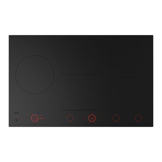
Your hob Induction hob (depending on the model) Since the appliances for which these instructions were drawn up may have different features, some functions or equipment may be described in the manual that may not be present in your appliance. 1. -
Page 10: Use
Using the touch controls • The touch controls may take some getting used to if you are used to other (rotary) controls. Place the tip of your finger flat on the control to achieve the best results. You do not have to apply any pressure. -
Page 11: How Does Induction Work
How does induction work A magnetic field is generated in the appliance. By placing a pan with an iron base on a cooking zone, a current is induced in the pan base. This induced current generates heat in the base of the pan. Easy The electronic controls are accurate and easy to set. -
Page 12: Pans
Pans Pans for induction cooking Induction cooking requires a particular quality of pan. WARNING! Pans that have already been used for cooking on a gas hob are no longer suitable for use on an induction hob. Only use pans that are suitable for induction cooking with a thick base (minimum 2.25 mm) and a flat base. -
Page 13: Induction Noises
WARNING! Never use pans with a misshapen base. A hollow or rounded base can interfere with the operation of the overheating protection, so that the appliance becomes too hot. This may lead to the glass top cracking and the pan base melting. Damage arising from the use of unsuitable pans or from boiling dry is excluded from the guarantee. -
Page 14: Power Level Settings
Power level settings Because the settings depend on the quantity and composition of the contents of the pan, the table below is intended as a guideline only. Level Purpose • simmer bouillon Use settings 1 - 5 to: • stew meats •... -
Page 15: Control Panel
Control panel (lay-out of user interface depends on model) 1. Wi-Fi/Connectivity 2. Pause • Key lock for cleaning • Pause and resume cooking 3. On/Off • Child lock 4. Hood control • Minus • • Plus • Lighting • Display 5. -
Page 16: Indications On The Display
Indications on the display In display Status Power level ‘0’ for a cooking zone Power level that is set for a cooking zone; 1 = low / 12 = high boost Boost function active Locking function is activated; the control panel is locked Residual heat indicator;... -
Page 17: Operation
Operation Switching the hob on/off Touch the on/off key to switch on the hob. A short beep will be emitted. Rings on all sliders will light up, then slider will gradually fade out. Slider will only remain lit on the selected cooking zones on which you have the pans placed. -
Page 18: Cooking
Operation INFORMATION! Child lock should be activated before the start of cleaning to avoid accidentally switching on the hob. Cooking Three cooking modes are available: 1. Standard cooking with power levels 2. Cooking with the PLUS menu 3. Hestan Cue cooking by measuring cookware temperature Standard cooking Place the pan on a certain cooking zone. -
Page 19: Move Function
Operation INFORMATION! To avoid overheating, the electronic control system may automatically deactivate boost prematurely and decrease the power level to 12. If there is no suitable pan on the cooking zone, the set level of temperature will flash. After one minute, the cooking zone will be switched off. -
Page 20: Pause
Operation To activate this mode, touch two sliders at the same time for 3 seconds. All zones must be inactive and Celsius°Cooking pans should not be assigned. To turn off this mode, tap any two sliders at the same time. In this mode, the hob does not warn of an empty cooking zone, even if there is no suitable pan placed on any cooking zone. -
Page 21: Time Functions
Operation Time functions Every cooking zone has two timers: a count-down program timer and a stopwatch (count-up timer). Count-down timer The count-down timer makes the cooking process easier by allowing you to set the cooking time for the selected cooking zone. When the time set on the timer expires, the cooking zone will automatically switch off and emit an acoustic signal. -
Page 22: Hot Cooking Zone
Operation Cooking time display stopwatch The stopwatch can be used to see how long you have been continuously cooking on the selected cooking zone and starts counting automatically in the background. • Press the stopwatch key. • Stopwatch time will be displayed on the cooking zone display unit. •... -
Page 23: Cooking With The Plus Menu
Grill This function is exclusively for bridged cooking zones, that are combined to a larger cooking zone. Grilling is optimized for ATAG induction accessories grill plate and teppanyaki. But it will also work with different cookware, but perhaps less accurate. - Page 24 Operation INFORMATION! Up to value 94 °C the programs allow the hob to reach and maintain automatically the set temperature by measuring the glass surface temperature. This will avoid liquids overflowing and burning on the bottom of the pan. INFORMATION! From 100 °C and higher temperatures the programs will heat up cookware with different timed power steps.
-
Page 25: Cooking With Celsius°Cooking
This equipment lets you unlock the full power of Celsius°Cooking , reading and communicating exact information about the temperature of your ingredients, giving perfect results. The equipment Probe Frying pan Chef's pot Find out more at www.celsiuscooking.com, www.atag.nl, and www.atag.be. -
Page 26: Cooking With Celsius°Cooking Cookware
Operation Cooking with Celsius°Cooking cookware and Hestan Cue programs This option involves cooking using either the Celsius°Cooking cookware frying pan or pot’s that continuously measures the temperature inside the cookware or the Celsius°Cooking temperature probe. All use Bluetooth connection to send information about the temperature to the cooking hob. Preparing the system Before you start cooking, please make sure you complete all the preparation steps. - Page 27 Operation Insert the Celsius°Cooking™ Probe into a cooking pan The Celsius°Cooking Probe can be used with different types and sizes of pans. Due to the use of a suspension bracket with different holes, the Probe can be suspended in different ways. 1.
- Page 28 Operation Celsius°Cooking™ Cookware 1. Insert an AAA battery in the panhandle (negative (-) end goes in first). 2. Insert the handle cap end into the panhandle and turn it a quarter to secure. NOTE! Do not exchange the handle cap of a chef's pot (31620) with that of a frying pan (31619) or vice versa.
- Page 29 Operation Using the probe as a cooking thermometer When a Celsius°Cooking probe is used it can also be used as a thermometer to just monitor e.g. the core temperature of a certain dish. This can be done on normal level cooking or PLUS menu programs.
-
Page 30: Step-By-Step Cooking Guide On Celsiuscooking.com
Operation Step-by-Step cooking guide on CelsiusCooking.com The best tasting food is prepared at the right temperature and for the right length of time. The ability to set temperature instead of power levels supported by how-to (video) guidance lets you create chef-like meals cooked to perfection. -
Page 31: Hood Control
Operation Hood control If you own a compatible RF enabled hood, it can be connected to your induction hob. To pair and customize the behaviour of your hood see chapter: Settings. Parameter hth (Hob to Hood) is used for pairing, while Hst and Hsc effect the behaviour of your hood so you can customize it according to your kitchen habbits. -
Page 32: Connectlife And Wi-Fi
ConnectLife and Wi-Fi ConnectLife-app and Wi-Fi connection The hob is equipped with a Wi-Fi module that allows the appliance to connect to the internet via your home network and to use it with the ConnectLife-app, installed on a mobile device like a smartphone or tablet. - Page 33 ConnectLife and Wi-Fi Proceed on the mobile device in the ConnectLife-app: 7. Connect your mobile device to the Wi-Fi network of the appliance when asked. 8. When your mobile asks whether to keep the connection, despite no internet connection, choose yes.
- Page 34 ConnectLife and Wi-Fi Unpair all users This option requires that the connection setup has been performed successfully and the hob is connected to the cloud (Wi-Fi key is constantly full lit). 1. Select option ‘U’ in the Wi-Fi menu to unpair all users and disconnect from the cloud. •...
-
Page 35: Firmware Update
Firmware Update The cooking hob, equipped with a Wi-Fi module, can receive updates of the appliance firmware (for example improved function updates or safety relevant updates). This requires, that the cooking hob is connected to the cloud and ConnectLife app with a registered user account. If this is not yet established, please proceed with the chapter for Wi-Fi Connectivity. -
Page 36: Settings
Settings You can tailor the behaviour of this induction hob to suit your cooking style! There are various settings available for adjustment. While there are no pans on any zone, touch any slider with two fingers and keep it pressed for 3 seconds. - Page 37 Settings Atl– Auto timer While on, stopwatch (count-up timer) starts counting in the background whenever a cooking zone is activated. While off, Automatic stopwatch timer stopwatch must be activated manually and starts counting from 0:00. ACL - Auto child lock While on, the hob is automatically locked at every switch off.
- Page 38 Settings FoA - Firmware update over the To receive firmware updates for the cooking hob, you need to be paired to the cooking hob via the mobile app. You will receive a notification, or you can check available firmware updates on the mobile app menu for updates.
-
Page 39: Maintenance
Maintenance Cleaning INFORMATION! Set the locking function before you start cleaning the hob. We recommend that you clean the appliance after each use. This prevents that over cooked food can damage the glass surface. Daily cleaning 1. Use a damp cloth and a mild cleaning agent (washing-up liquid) to clean the appliance. 2. -
Page 40: Troubleshooting
Troubleshooting General If you notice a crack in the glass top (however small), switch the hob off immediately, unplug the hob, turn off the (automatic) fuse switch(es) in the meter cupboard or, in the event of a permanent connection, set the switch in the power supply lead to zero. Contact the service department. Troubleshooting table If the appliance does not work properly, this does not always mean that it is defective. - Page 41 Troubleshooting Error code Symptom Possible cause Solution U400 U 400 appears on Voltage of the mains is too Connect the appliance in display with continuous high. accordance to rating plate sound tone. and instructions. E2 appears on display. Empty pan was heated on Wait for cooking zone to cool the cooking zone.
-
Page 42: Troubleshooting Wi-Fi
Troubleshooting Troubleshooting Wi-Fi Symptom Possible cause Solution Wi-Fi icon not shown Wi-Fi disabled The hob must be switched off, then touch the on/off key hold it for 5 seconds. Wi-Fi setup failed Home network issues. Check that your home network signal is strong and internet connection is working. -
Page 43: Installation
Installation Safety If the safety instructions and warnings are not followed, the manufacturer cannot be held responsible for any resulting damage. • This appliance should only be connected by a registered installer. • Check the appliance for transport damage. Do not connect a damaged appliance. - Page 44 Installation • Prior to installation, ensure that the local distribution conditions (voltage and frequency) and the adjustment of the appliance are compatible. • Means for disconnection must be incorporated in the fixed wiring in accordance with the wiring rules. • The voltage, frequency, power and the country for which the appliance has been designed are shown on the appliance rating plate.
-
Page 45: Installing A Built-In Hob
Installation WARNING! Failure to use screws or fasteners for installation as described in the installation instructions may result in electric shock. Service • Disconnect the appliance from the mains supply before starting any repair work. • Faulty parts may only be replaced by original parts. The manufacturer can only guarantee that original parts meet safety requirements. - Page 46 Installation Dimensions A (mm) B (mm) C (mm) D (mm) 38 cm 64 cm 72 cm 80 cm 90 cm 111 cm 1114 A (mm) B (≥mm) C (mm) D (≥mm) E (≥mm) 38 cm 350-352 490-492 64/72 cm 560-562 490-492 80 cm 750-752...
-
Page 47: Air Vents In The Lower Kitchen Cabinet
Installation Air vents in the lower kitchen cabinet • Normal operation of the induction cooking hob electronic components requires sufficient air circulation. Lower cabinet without an oven • There must be an opening with a height of no less than 140 mm along the entire width of the cabinet in the cabinet rear wall. -
Page 48: Flush-Mount Installation Into The Worktop
Installation Flush-mount installation into the worktop Appliances without faceted edges or decorative frames are suitable for flush mounting. brushed edge decorative frame Installing the appliance The appliance may only be installed into a temperature- and water-resistant countertop, such as a countertop made of (natural) stone (marble, granite), or solid wood (the edges along the cut-out have to be sealed). - Page 49 Installation Removing the built-in appliance Disconnect the appliance from the power mains. Use a suitable tool to remove the silicone gasket from the perimeter. Remove the appliance by pushing it upwards from the bottom side. WARNING! Do not attempt to remove the appliance from the upper side of the counter! WARNING! The service department shall only be responsible for repair and servicing of the cooking hob.
- Page 50 Installation Installation into the worktop - flush mount (depending on the model) A (mm) B (mm) C (mm) D (mm) 72 cm 80 cm 90 cm 111 cm 1110 A (mm) B (mm) C (mm) D (mm) (≥mm) (≥mm) (≥mm) 72 cm 724-725 560-562...
-
Page 51: Fitting The Foam Gasket
Installation Fitting the foam gasket INFORMATION! Some appliances come with the gasket already fitted! Before installing the appliance into a kitchen worktop, attach the foam gasket supplied with the appliance to the bottom side of the glass ceramic hob. • Remove the protective film from the gasket. -
Page 52: Electrical Installation
Electrical installation Connecting the cooking hob to the power mains • Power mains protection must conform to the relevant regulations. • Before connecting the appliance, make sure the voltage indicated on the rating plate conforms to the voltage in your power mains. •... - Page 53 Electrical installation Current limiter Connection type Power cord Number and cross section settings type of Power cord wires 1x16A 1 phase, 1 neutral conductor H05V2V2-F 3x1,5 mm² 1x13A 1 phase, 1 neutral conductor H05V2V2-F 3x1,5 mm² 1x10A 1 phase, 1 neutral conductor H05V2V2-F 3x1,5 mm²...
- Page 54 Electrical installation The following connections are possible. 1 phase, 1 neutral conductor (220–240 V~, 50-60 Hz) To reach the rated maximum power a fuses of 32A is needed. Install a jumper between terminals 1 and 2 and between terminals 4 and 5.
- Page 55 Electrical installation 2x06A 2 phases, 1 neutral conductor H05V2V2-F 4x1,5 mm² 2x16A 2 phases, 2 neutral conductors H05V2V2-F 5x1,5 mm² (only for NL) 2x32A 2 phases, 1 neutral conductors H05V2V2-F 4x4,0 mm² 1x48A 1 phase, 1 neutral conductor H05V2V2-F 3x6,0 mm² 1x35A 1 phase, 1 neutral conductor H05V2V2-F...
- Page 56 Electrical installation (only for NL) 2 phases, 2 neutral conductors (220–240 V 2-2N~, 50-60 Hz) To reach the rated maximum power two fuses of 16A are needed. The 2 fases (L1 and L2) should be secured by only one and the same earth leakage breaker.
- Page 57 Electrical installation Voltage between line conductors must be 220–240 V~. 2 phase conductors (220–240 V~, 50-60 Hz) L1 = black/brown L2 = blue = yellow-green For appliance types: BI1CA…, BI6CA…, BI6CB…, BI7CA…, BI8CA…, BI8CB…, BI9CE… NOTE! Note: The appliance type can be found on the rating plate on the bottom of the appliance. Voltage between lines must be 220–240 V~.
- Page 58 Electrical installation 3 phases (220–240 V~, 50-60 Hz) To reach the rated maximum power a fuses of 32A is needed. Install a jumper between terminals 4 and 5. For appliance types: BI9CA…, BI9CB…, BI9CC… . NOTE! Note: The appliance type can be found on the rating plate on the bottom of the appliance. Voltage between lines must be 220–240 V~.
-
Page 59: Current Limiter
Electrical installation 2 phases (220–240 V~, 50-60 Hz). To reach the rated maximum power a fuse of 48A is needed. Install a jumper between terminals 1 and 2 and between terminals 4 and 5. 3 phases (220–240 V~, 50-60 Hz). To reach the rated maximum power a fuses of 48A is needed. -
Page 60: Environmental Aspects
Environmental aspects Disposal of packaging and appliance In the manufacturing of this appliance durable materials were used. Make sure to dispose of this equipment responsibly at the end of its lifecycle. Ask the authorities for more information regarding this. The appliance packaging is recyclable. The following may have been used: •... -
Page 61: Compliance Information
2402.0MHz - 2480.0MHz Carrier Output: <10dBm Emission type: Hereby, Atag declare that the radio equipment mentioned above is in compliance with Directive 2014/53/EU. The full text of the EU declaration of conformity is available at the following internet address: www.celsiuscooking.com/DoC. - Page 62 The appliance identification card is located on the bottom of the appliance. Stick the appliance identification card here. www.atag.nl www.atag.be 828824...
Need help?
Do you have a question about the HI21471 and is the answer not in the manual?
Questions and answers