Advertisement
Quick Links
Advertisement

Related Manuals for aivituvin GUT 05


Summary of Contents for aivituvin GUT 05
- Page 1 INSTRUCTION MANUAL GUT 05 www.aivituvin.com...
- Page 3 NOTICE Please retain these instructions for future reference. Firmly secure all bolts,screws and knobs before use. Reconfirm that all bolts,screws,and knobs are secure every 90 days. Fasten screws loosely during initial assembly. Do not fully tighten screws until the item is completely assembled. Do not use or store this item in the proximity of open flame or flammable/combustible chemicals.
-
Page 4: Tools Required
TOOLS REQUIRED PHILLIPS DRILL 2PERSON APPROXIMATELY SCREWDRIVER (RECOMMENDED) ASSEMBLY 45MIN. ASSEMBLY HARDWARE M6.0x35mm SCREW M8.0x50mm SCREW 2PCS 8PCS M3.5x25mm SCREW M3.5x35mm SCREW 8PCS+1 spare 60PCS+1 spare M3.0x16mm SCREW 24PCS+1 spare... - Page 5 PARTS Bench Seat Backrest Bench Frame 2 PCS 2PCS 2PCS Side Frame Canopy Support Frame Panel 2PCS 4PCS 2PCS Frame Support Rectangle Canopy Frame Triangle Canopy Frame 3PCS 2PCS 2PCS...
- Page 6 PARTS Sand Screen Stopper Seat Divider 6PCS 6PCS Canopy...
- Page 7 PARTS...
-
Page 8: Product Assembly
PRODUCT ASSEMBLY ① Attach three part J seat dividers to a part C bench seat with 6xP3 screws. ② Repeat on other bench seat. ① Attach a part B backrest to a part C bench with 6xP5 screws, three screws per hinge. ② Repeat on other bench seat. - Page 9 PRODUCT ASSEMBLY Attach part D and part E together by 8xP3 screws on each side. Place sandbox on the part L sand screen.
- Page 10 PRODUCT ASSEMBLY ① Attach a part G frame support inside of part E with 4xP4 screws. ② Then attach a part F canopy support from outside of part E with 4xP2 bolts. Repeat on other sandbox side.
- Page 11 PRODUCT ASSEMBLY Attach two part A bench frames with 8xP3 screws. Attach two assembled benches with 12xP5 screws, three screws per hinge.
- Page 12 PRODUCT ASSEMBLY Attach three part K stopper with 6xP3 screws, two screws per stopper. ① Repeat attach the part K on the other side. ② Attach two part I to part F canopy support by 1xP1 each side.
- Page 13 PRODUCT ASSEMBLY Attach three part H to part I with 12xP3 screws.
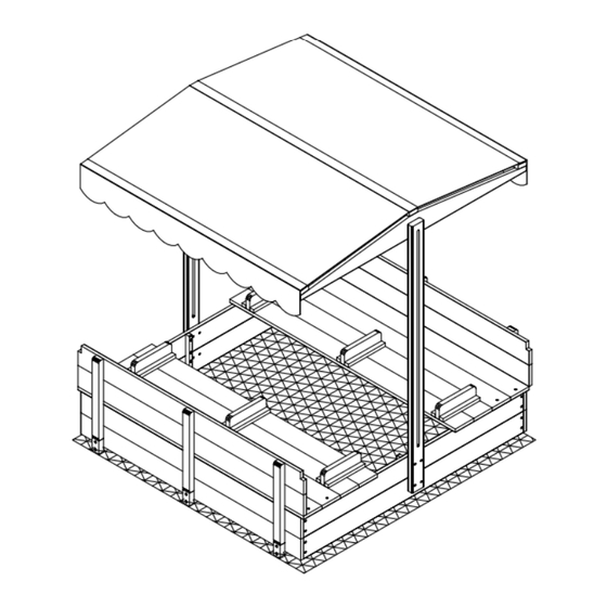
- Page 14 PRODUCT ASSEMBLY Stick the canopy by the magic sticks.
- Page 16 WARNING Manufacturer and seller expressly disclaim any and all liability for personal injury,property damage or loss,whether direct,indirect,or incidental,resulting from the incorrect attachment,improper use,inadequate miantenance,or neglect of this product.
Need help?
Do you have a question about the GUT 05 and is the answer not in the manual?
Questions and answers