Table of Contents
Advertisement
Quick Links
HDL-MWM70-RF.12
Wireless Curtain Control Motor
Datasheet
Issued: August 18, 2020
File Edition: V1.0.1
Figure 1. Wireless Curtain Control Motor
1
Figure 2. Dimensions
4
6
7
8
5
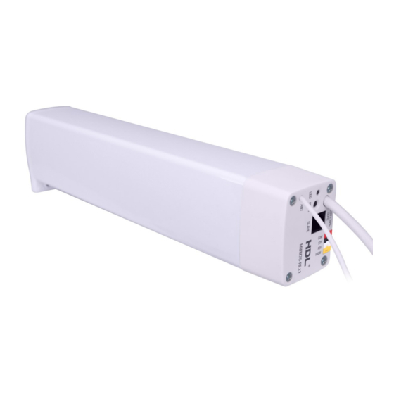
Figure 3. Components - Side View
11
Figure 4. Components - Side View
Overview
Wireless Curtain Control Motor (See Figure 1)
a specified percentage position after configuration with the wireless gateway. The Wireless Curtain Con-
trol Motor can be manually pulled no matter it is power-on or power-off. The motor also supports overheat
protection.
Functions
Curtain distance measurement.
■
Working mode: long pull mode, short pull mode, free
■
Percentage control.
■
Communication: wireless.
■
Supports online upgrading.
■
Supports easy programming.
■
With clutches of new generation and precise planetary deceleration structure, the operating noise is
■
down to around 40dB.
Dry contact switch to open, close and stop the curtain.
■
Strong power provided by AC motor.
■
Medium straight line and curved opening and closing curtain appropriate for all occasions.
■
Important Notes
Horizontal pull is 8kg with up to 50kg load.
■
The motor should work in conjunction with the wireless gateway.
■
Product Information
Dimensions - See Figure 2
Components - See Figure 3 - 4
1. Latch
2. Dry contact switch to open, close, and stop the curtain. (COM+FROW is on, COM+REV is off,
COM+STP is stop) through the electronic switch.
2
3. RJ11 6P network port, connect to the master and slave. It supplies the working voltage for slave.
4. AC220V power input (brown: L, blue: N, yellow green: G. A power cord of about 1m provided by de-
fault.)
3
5. Antenna
6. LED indicator
7. Programming button
8. 6P network interface
9. Unlock sign
10. Locked sign
11. Motor terminal
Pull the latch to unlock direction, and then insert the motor terminal into the C-Driver Unit. Then, push the
9
latch into the locked hole.
Safety Precautions
10
The installation and commissioning of the device must be carried out by HDL or the organization
■
designated by HDL. For planning and construction of electric installations, the relevant guidelines,
regulations and standards of the respective country are to be considered.
HDL does not take responsibility for all the consequences caused by installation and wire connection
■
that are not in accordance with this document.
Please do not privately disassemble the device or change components, otherwise it may cause me-
■
chanical failure, electric shock, fire or body injury.
Please resort to our customer service department or designated agencies for maintenance service.
■
The warranty is not applicable for the product fault caused by private disassembly.
Package Contents
HDL-MWM70-RF.12*1 / Buspro connector*1 / Network cable*1 / Datasheet*1
enables controls of opening, closing, stopping or opening to
mode.
1/2
Advertisement
Table of Contents

Subscribe to Our Youtube Channel
Related Manuals for HDL buspro WIRELESS HDL-MWM70-RF.12


Summary of Contents for HDL buspro WIRELESS HDL-MWM70-RF.12
- Page 1 Pull the latch to unlock direction, and then insert the motor terminal into the C-Driver Unit. Then, push the latch into the locked hole. Safety Precautions The installation and commissioning of the device must be carried out by HDL or the organization ■ Figure 3. Components - Side View designated by HDL.
- Page 2 The symbol “×” indicates that the content of the hazardous substance in at least one of the homogeneous Technical support materials of the part exceeds the limit requirement specified in the Standard IEC62321-2015. E-mail: hdltickets@hdlautomation.com Website: https://www.hdlautomation.com ©Copyright by HDL Automation Co., Ltd. All rights reserved. Specifications subject to change without notice.
Need help?
Do you have a question about the buspro WIRELESS HDL-MWM70-RF.12 and is the answer not in the manual?
Questions and answers