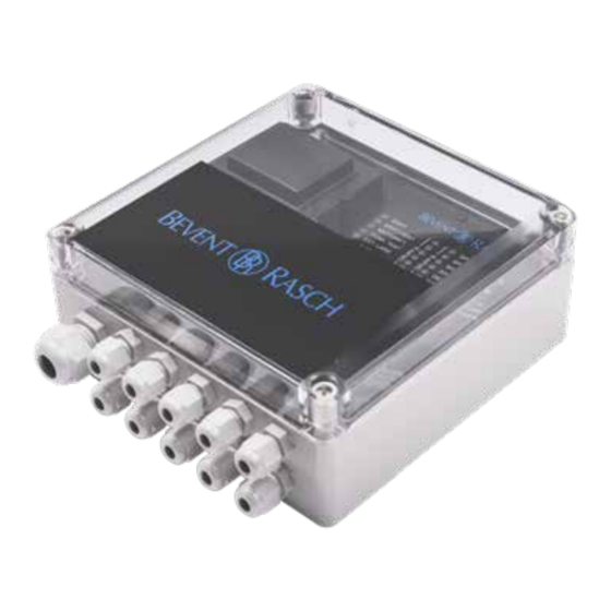
Summary of Contents for Bevent Rasch RCBK4-MOD
- Page 1 RCBK4/-MOD Control unit Monitoring system MRB FIRE SAFETY 28/08/2018 www.bevent-rasch.com...
-
Page 2: Quick Facts
• Triggered detector network to a minimaster RCMM for centralised registration, • Damper fault control and monitoring. RCBK4-MOD is used for connec- • External incoming alarm tion to Modbus. Function tests can also be initiated by an • Power failure external switch. -
Page 3: Operating Indicators
RCBK4 will enter alarm mode and the main closed simultaneously alarm will be triggered. Use RCBK4-MOD to connect to a Modbus network. The Function when the LED for DAMPER POSITION is off: network can have free topology and the following informa- - Lit 0.1 s/off 0.1 s in case of overload on one of outputs... -
Page 4: Specification
315 mA tube fuse, delay EMC: EN 50081-1 (1992) Specification EN 50082-2 (1995) Control unit RCBK4 Technical data RCBK4-MOD - ” - RCBK4-MOD - for connection to Modbus network Interface: RS485 (MODBUS-RTU) Communication ACCESSORIES: speeds: 9600/19200 baud, 8 bit, RCKD/-RD... -
Page 5: Dimensions And Weight
DETAKTORER LARM TEST ÅTERSTÄLL DETEKTORER SERVICE RCBK 4 10 x M12 (3-6,5 mm) 1 x M20 (6-12 mm) Weight 1,8 kg Block diagram RCBK4, RCBK4-MOD DRIFT SPJÄLL 1 LÄGE SPJÄLL 1 FEL DRIFT VENT NATTDRIFT SPJÄLL 2 LÄGE FUNK.TEST SPJÄLL 2 FEL EXT. - Page 6 Brand-/Brandgasspjäll BSKC6 EI60 Monitoring system MRB – Control unit RCBK4 Wiring diagram RCBK4, RCBK4-MOD FUNC NIGHT MAIN DET SERV OPER. Damper 1 Damper 2 Damper 1 Damper 2 ALARM TEST OPER. ALARM ALARM AIR H. UNIT Group A Group B...


Need help?
Do you have a question about the RCBK4-MOD and is the answer not in the manual?
Questions and answers