
Related Manuals for Bevent Rasch Fenix 2


Summary of Contents for Bevent Rasch Fenix 2
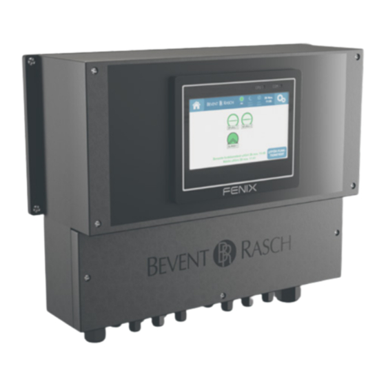
- Page 1 FENIX2 Monitoring system FIRE SAFETY Commissioning instruction 21/01/2021 www.bevent-rasch.com...
-
Page 2: Table Of Contents
FENIX2 Monitoring system – Commissioning instruction Contents General ......................2 Products ......................3 1. Installation ....................3 2. Connection ....................4 3. Commissioning ................... 6 Functions ......................9 Management and service ................10 General Control unit FENIX2 contains electronic components that can be damaged if used incorrectly. -
Page 3: Products
FENIX2 Monitoring system – Commissioning instruction Products System structure FENIX2 FENIX2 is a control unit with connections for 1-2 fire dampers and smoke detector circuits that are automatically detected during commissioning. FENIX 0-10 V module When using regulating fire dampers, regulation can be performed in two different ways, either via a local 0-10 V signal out at the damper or via master communication (Modbus TCP or BACnet IP). -
Page 4: Connection
FENIX2 Monitoring system – Commissioning instruction 2. Connection Connect dampers, smoke detectors and other connections according to the following connection instructions when the unit is powered down. NOTE! If a smoke detector is not connected, then noterminating resistance should be fitted. The connection instructions for the ON/OFF damper (open/closed) are different from the regulating 0-10 V damper, see the connection instructions. - Page 5 FENIX2 Monitoring system – Commissioning instruction 2. Connection cont. Connection terminals Function Description 4+5, 11+12 Connection of smoke detector Each smoke detector circuit should have a 2.2 kOhm's resistance mounted at the circuits end of the circuit, see the wiring diagram. The terminating resistance of 2.2 kOhm is connected to the last detector in each circuit.
-
Page 6: Commissioning
FENIX2 Monitoring system – Commissioning instruction 3. Commissioning 1. Power the unit with 230 V AC 2. Press START on the display and follow the commissioning instructions below. The start page when powered up. If a fire damper is connected incorrectly or does not work, a red icon will appear. - Page 7 FENIX2 Monitoring system – Commissioning instruction Symbol descriptions SLAVE 1 SLAVE 1 SLAVE 1 DAMPER 1 DAMPER 1 DAMPER 1 AMPER AMPER DAMPER 1 AMPER AMPER DAMPER 1 AMPER AMPER DAMPER 1 AMPER AMPER Closed Damper in Open damper “DAMPER 1” “0-10 V”...
-
Page 8: Functions
FENIX2 Monitoring system – Commissioning instruction Function description Functions and settings via the display Automatic functions integrated in FENIX2 Date and Time Dynamic troubleshooting diagrams The date and time are set from the factory, but can be eas- Instead of the traditional troubleshooting documents that ily changed on-site if necessary. -
Page 9: Management And Service
FENIX2 Monitoring system – Commissioning instruction Management and service The FENIX2 system is designed to facilitate management and service by present- ing troubleshooting suggestions and measures for each specific service issue. This means that you do not have to keep any troubleshooting manuals and other documentation. - Page 10 FENIX2 Monitoring system – Commissioning instruction Tel +46 (0)33 - 23 67 80 Tel +46 (0)8 - 54 55 12 70 BORÅS STOCKHOLM...
- Page 11 FENIX2 Monitoring system – Commissioning instruction Tel +46 (0)33 - 23 67 80 Tel +46 (0)8 - 54 55 12 70 BORÅS STOCKHOLM...
- Page 12 www.bevent-rasch.com...
Need help?
Do you have a question about the Fenix 2 and is the answer not in the manual?
Questions and answers