
Subscribe to Our Youtube Channel
Related Manuals for Solo 526L


Summary of Contents for Solo 526L
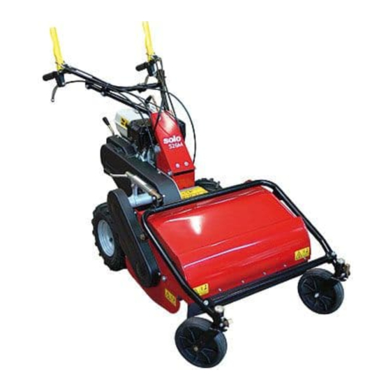
- Page 1 FLAIL MOWER WITH HONDA GX 270 ENGINE MODEL 526L OPERATING AND SAFETY INSTRUCTIONS . : G08000 16/12/2003...
- Page 3 Contents of the FLAIL MOWER Manual Use of the Manual Notices on the machine Technical data Lifting and transportation Main parts of the machine Controls and adjustments Assembly instructions for the handlebars and front support with wheels Safety information a) General instructions b) Training c) Preparation d) Working use...
-
Page 4: Operating And Safety Instructions
PERATING AND AFETY NSTRUCTIONS FLAIL MOWER MOD. 526L FOREWORD This machine may only be utilized for the purpose for which it was designed, i.e. agricultural use, for the cutting of shoots, grass and brushwood. Any other use other than that stated, not covered or deducible from this Manual and the enclosed Engine Manual is "PROHIBITED". - Page 5 OTICES ON THE MACHINE In this Manual all safety information appears in special boxes headed "WARNING". WARNING This heading is used to draw the user's attention to hazardous areas or moving parts of the machine. It is also used in instances where failure to comply with the instructions given may result in injury to persons and animals or damage to property.
- Page 6 Danger of injury to both upper and lower limbs.Do not put hands or feet inside the cutting element while in motion. Danger of getting caught up in rotating parts. Do not put hands in the rotating parts. Danger of foreign objects being thrown outwards. Safety goggles must be worn.
-
Page 7: Service Brake
526L ECHNICAL DATA OF THE MODEL ENGINE petrol, HONDA GX 270 ENGINE CAPACITY 6.6 kW (9.0 HP) ENGINE FILTER Dry filter WORKING WIDTH 75 cm CUTTING HEIGHT adjustable 20 - 80 mm CUTTING SYSTEM 40-flail rotor SPEED GEARS 3 forward gears – 2 reverse gears... - Page 8 Environmental conditions Unless otherwise stated at the time of ordering it is understood that the machine is to work normally in the environmental conditions covered by the following points. Environmental conditions other than those described may cause mechanical breakage resulting in the creation of dangerous situations for persons. LTITUDE The altitude of the place in which the machine is to be used must not exceed 1500 m above sea level.
-
Page 9: Main Parts Of The Machine
AIN PARTS OF THE MACHINE The machine consists of the following main parts Forward clutch control lever Accelerator control lever Emergency brake control lever Flail rotor clutch control lever Right wheel release lever Left wheel release lever Engine Front guard Cutting height adjustment lever Handlebar height adjustment lever On/off switch (1/0) -
Page 11: Controls And Adjustments
ONTROLS AND ADJUSTMENTS A) FORWARD CLUTCH CONTROL LEVER This lever only has two positions: engage and disengage. Lowering the lever engages the clutch and releasing it disengages the clutch. The service brake is connected to this lever. The brake operates automatically when the clutch is disengaged. -
Page 12: Front Guard
H) FRONT GUARD The front guard ( Fig. 1, ref. H) opens or closes automatically according to the amount of grass to be cut. Use of the machine with the guard left open is strictly prohibited. This may cause the outward projection of objects. The guard may only be set in the open position during flail replacement operations with the machine switched off. - Page 13 SSEMBLY INSTRUCTIONS FOR THE HANDLEBARS AND FRONT SUPPORT WITH WHEELS The flail mower is delivered with the front support with wheels disassembled. Re- move the cardboard packaging or crate (to be disposed of in an appropriate man- ner, in accordance with current regulations in force). To assemble, proceed as follows : - Position the front support with front wheels and connect the height adjustment piece (Fig.
-
Page 14: Safety Information
AFETY INFORMATION Before using the flail mower it is essential that the operator has understood the warnings, do's and don'ts and precautionary measures given in this manual and in the engine manual: the prevention of injury to the operator, third parties, animals or objects directly depends on observance of these instructions. - Page 15 ! Supervise the clothing of personnel operating the machine: a long-sleeved jacket with close-fitting cuffs, long, close-fitting trousers, heavy-duty footwear, and a protective cap or helmet should be worn. Avoid wearing loose-tailed clothing, unbuttoned jackets or torn, undone or partially zipped up items to pre- vent them from being caught up in the moving parts.
- Page 16 WARNING. During work operations the grass is shredded and expelled by the machine. However, if the grass is damp it tends to build up inside the flail housing, thus leading to the incorrect feeding of the grass to be cut. The result is that even on short grass the engine may tend to cut out.
-
Page 17: Transportation Of The Machine
FTER USE ! Before moving away from the machine, place the gear lever in neutral (see fig- ure 2, ref.N) and switch off the engine by moving the switch (Fig.2,ref.M) to the 0 position. ! For greater safety shut off the feed cock (Fig. 4). RANSPORTATION OF THE MACHINE OADING AND UNLOADING FROM A VEHICLE ! For transportation it is preferable to use a vehicle with an open bed. -
Page 18: Operations To Be Carried Out Before Switching On
10. D ESCRIPTION OF THE SAFETY AND GUARD SYSTEMS WARNING The safety devices must never be tampered with. It is necessary to understand how they work and safeguard their efficiency and correct operation. In the instance of doubt, prob- lems or malfunction contact your dealer. FORWARD CONTROL AND FLAIL MOVEMENT LEVERS When released both of these levers instantly disengage the transmission con- nected to them, thus automatically engaging their respective brakes, hence the... -
Page 19: Starting And Driving The Flail Mower
12. S TARTING AND DRIVING THE FLAIL MOWER The machine can be switched on once all the aforementioned preliminary opera- tions have been carried out. Place the feed cock in the OPEN position (direction shown by the arrow) ( fig. 4) Bring the choke to the CLOSED position for a cold start (direction shown by the arrow, Fig. - Page 20 RIVING THE MACHINE WARNING. When using the machine for the first time it is advisable to get the feel of it by executing manoeuvres on flat ground free of foreign objects. Cut in a straight line at low speed, slightly overlapping the section cut pre- viously.
-
Page 21: Cutting Tips
13. C UTTING TIPS 1) Before commencing cutting operations, read the safety instructions given in the previous sections. 2) Before engaging flail movement using the relative lever ( figure 1, ref. D) the guard ( fig. 1, ref. H) must be fully lowered to prevent the outward projection of objects. - Page 22 Fig. 5 B1) R . A) IGHT AND LEFT WHEEL RELEASE CABLES Inspect or move the cable sheathing slightly to ensure play of 1-2 mm between the upper part of the cable and the adjustment screw (Fig. 5,. ref. A, point a). If there is none, restore to ideal position using the relative adjustment screw.
- Page 23 B2)F . B) LAIL HOLDER ROTOR CONTROL CABLE Make sure that there is no play between the upper end of the cable and the ad- justment screw. If there is, or if the cable has stretched, restore to ideal position using the relative adjustment screw.
-
Page 24: Brake Adjustment
B3) F ORWARD CONTROL CABLE (Fig. 5 ref. C point b , and ref. D point b) Make sure that there is no play between the upper end of the cable and the ad- justment screw. If there is, or if the cable has stretched, restore to ideal position using the relative adjustment screw. - Page 25 Fig. 7 C1) R OTOR RAKE Loosen and remove the screw ( ref. B fig. 7) Remove the brake adjustment device ( ref. A fig. 7) Shorten or lengthen the threaded pin as necessary (ref. D fig. 7) by turning clock- wise or anti-clockwise.
-
Page 26: Belt Replacement And Adjustment
Fig. 8 D) BELT REPLACEMENT AND ADJUSTMENT If a belt breaks or becomes worn it is advisable to change both belts connected to the engine at the same time. The replacement of just one belt alone may give rise to adjustment problems. Conversely, the blade rotor control belt is completely independent of the others, so for its replacement or adjustment carry out the following: D1) B... - Page 27 Fig. 9 Fig. 10...
- Page 28 To access the transmission belts and rotor brake adjustment device area, re- move the plastic guard (fig. 9 ref. D) and unscrew and remove the 4 screws shown in figure 9 ref.A. D2) F ORWARD Remove the brake adjustment device (Fig.7 Ref. A) by unscrewing the screw (Fig. 7 Ref.
- Page 29 . 12 . 13 . 14 E) C HECKING AND REPLACING THE FLAILS Always check the state of the flails before commencing work. Do not forget to switch the engine off! Checking and replacement of the flails requires the assistance of another person to hold the handlebars down to tilt up the front part of the machine.
- Page 30 The flails are reversible, so when they become blunt on one side they can be assembled on the other. Generally speaking, unless it's a question of only 1 or 2 flails, all the flails should be replaced at the same time to prevent the occurrence of vibration. Even the flail rotor holder (fig.
- Page 31 To remove the flails proceed as follows: 1. Switch off the engine and disconnect the spark plug wire 2. Adjust the cutting height to maximum 3. Open the front housing. 4. Check the state of the flails. 5. Check that the flails are not cracked, bent, excessively worn or broken. If they are, either reverse them (turning them 180°) or replace them.
-
Page 32: Maintenance And Storage
15. M AINTENANCE AND STORAGE ! All operations on the machine must be carried out exclusively by authorized personnel. ! Always switch off the engine when checking, adjusting or servicing the ma- chine. ! Allow the machine to cool down before inspection. ! The belt guard (Fig. - Page 33 Use of the machine does not require specific lighting. However, the recommended minimum amount of light (e.g. 200 lux) is enough to be able to read the notices on the machine and to operate it without running risks caused by poor light. G) CHECKING AND REPLACING THE TRANSMISSION OIL Check the transmission oil level using the relative level cap (Fig.
-
Page 34: Cleaning The Machine
16. C LEANING THE MACHINE Proceed in the following order: Switch off the engine and disconnect the spark plug wire; Clean the engine and the outside of the machine with a cloth soaked in a little oil. Clean all parts of the machine, particularly the starting unit, air filter, exhaust and carburetor. -
Page 35: Decommissioning And Scrapping
18. D ECOMMISSIONING AND SCRAPPING After the working life of the flail mower the user must have it dismantled and its components removed as per EEC directives or in accordance with current legis- lation in force in his country, taking particular care over the dismantling of the following materials of environmental impact: plastic parts rubber parts... - Page 36 20. W ARRANTY The flail mower has a 12-month warranty which starts from the day of purchase, (or up to 50 hours' service, if for individual use) or 6 months (or up to 50 hours' service, if for commercial use) excluding the engine, for which the warranty sup- plied by its manufacturer applies.
- Page 37 21. CE marking The plate bearing the CE mark gives the main characteristics and information for the identification of the flail mower. • Manufacturer's details • Machine model • Serial number • Year of construction • Capacity in kW • Weight in kg The above information must not be altered or modified in any way.
-
Page 38: Troubleshooting
22. T ROUBLESHOOTING The following table illustrates some problems which may arise during operation. FAULT CAUSE ACTION Grass ejection insufficient 1. Grass wet Wait until the grass has dried 2. Grass too long Go over the grass twice, changing the cutting height 3. - Page 39 Engine sluggish at switch on accelerator not in start-up 1. move the accelerator to the position intermediate position Choke not closed 2. Close the choke when cold. 3. Check the fuel tank and Petrol does not arrive remove any water or sedi- ment.
- Page 40 NOTES _________________________________________________________________________ _________________________________________________________________________ _________________________________________________________________________ _________________________________________________________________________ _________________________________________________________________________ _________________________________________________________________________ _________________________________________________________________________ _________________________________________________________________________ _________________________________________________________________________ _________________________________________________________________________ _________________________________________________________________________ _________________________________________________________________________ _________________________________________________________________________ _________________________________________________________________________ _________________________________________________________________________ _________________________________________________________________________ _________________________________________________________________________ _________________________________________________________________________ _________________________________________________________________________ _________________________________________________________________________ _________________________________________________________________________ _________________________________________________________________________ _________________________________________________________________________ _________________________________________________________________________ _________________________________________________________________________ _________________________________________________________________________ _________________________________________________________________________ _________________________________________________________________________...
-
Page 41: Ce Declaration Of Conformity
Stuttgarter Str. 41 D-71069 Sindelfingen declares under its own responsibility that the new machine type: FLAIL MOWER model: 526L with GX 270 engine serial number : ……………………. year of construction: 2004 described as follows: Machine for agricultural use for the cutting of shoots, grass and brushwood conforms to the Essential Health and Safety Requisites of Directive 98/37/CEE and sub- sequent amendments. - Page 43 G060000 1/13...
- Page 44 G060100 2/13...
- Page 46 G060200 3/13...
- Page 48 G060300 4/13...
- Page 50 G 0 6 0 4 0 0 5 / 1 3...
- Page 52 G060500 6/13...
- Page 54 G0 6 0 6 0 0 7 /1 3...
- Page 56 G060700 8/13...
- Page 58 G060800 9/13...
- Page 60 G060900 10/13...
- Page 62 G061000 11/13...
- Page 64 G061100 12/13...
- Page 67 G061200 13/13...
Need help?
Do you have a question about the 526L and is the answer not in the manual?
Questions and answers