Table of Contents
Advertisement
Quick Links
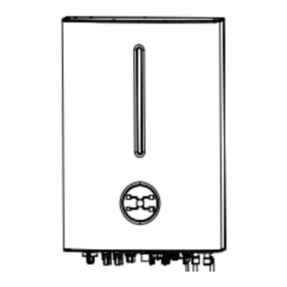
Hybrid Inverter(Hyper 3-5kW)
Preparation Tools
600
Electrical Connection Overview
This diagram indicates the wiring structure instead of the electric wiring standard of hybrid inverter.
1. For batteries with attached breaker, the external DC breaker could be omitted.
2. The recommended values in the table are for reference only.
Notice:
3. The actual values must comply with local standard and actual conditions.
4. Only for lithium battery which has BMS communication.
5. Direction of the CT cannot be connected in reverse,
please follow "→Inverter" direction to do the connection
B
System Connection Diagram (Applies to most countries)
If the battery is integrated
with a readily accessible
internal DC breaker, no
additional
DC breaker
is required.
• N and PE wiring via ON-GRID and BACK-UP ports of the inverter are differnet based on the regulation requirements of different regions.
Notice:
• Refer to the speci fic requirements of local regulations.
• Ensure that the grounding of BACK-UP is correctly and tightened. Otherwise, the BACK-UP function may be abnormal in case of grid failure.
Wiring Diagram
Packing List
Inverter *1
Bracket *1
PV Connectors
Wi-Fi Dongle *1
*2 or 4
Battery power
Expansion Bolts *4
Connectors *2
BMS Connector *1
DRM Connector *1
(for Li-Ion battery)
The image shown here is for reference only. The actual product and quantity are based on delivery.
Notice:
Installation requirements
Wall mounting
B
1 1 1
2
3
V
PE Cable Connection
Please prepare the cable before connecting as follows.
No.
Cable
Cross Section
4mm - 6mm
²
²
1
PV cables
AC cables
2
4mm - 6mm
²
²
Battery power cables
25mm
²
3
PE cable
4mm - 6mm
²
4
²
Unacceptable Installations
B
C
External Grounding (PE Cable) Connection
<2mm
<0~1.5 mm
PV Cable Connection
Step 1
Remove an appropriate length of the insulation layer from the PV Strings power cables.
Step 2
Connect the red wire to the positive metal terminal, and the black to the negative and crimp them using a crimping tool.
Step 3
Insert the crimped positive and negative power cables into the corresponding connectors until a "click" sound is heard.
Step 4
Tighten the locking nuts on the positive and negative connectors.
Step 5
Measure the voltage of every route Strings using a multimeter. Ensure that the polarities of the DC input power cables are correct.
Step 6
Insert the positive and negative connectors into their corresponding terminals of the inverter until a click sound is heard.
Positive metal terminals
1
Negative metal terminals
Click
Click
3
4
Click
Click
6
EPS Connector *1
CT *1
(Current Transformer)
Screws *1
Battery Temp. sensor
*1
Documents
(for Lead-acid battery)
Mounting
5
4
Cable diameter (mm)
Notice:
• Do not work with power on. All
12~10 AWG
operations, cables and parts specification
during the electrical connection shall be in
12~10 AWG
compliance with local laws and regulations.
• Disconnect the DC switch of the inverter
4 AWG
to power off the inverter before any electrical
connections.
10 AWG
Notice:
• Please avoid the following installations which will
damage the system or the Inverter.
• Any damage caused will not be covered by the warranty policy.
①M ulti inverters cannot be connected in parallel.
②S ingle PV string cannot be connected to multiple inverters.
③O ne battery bank cannot be connected to multiple inverters.
④T he EPS (backup) side cannot be connected to the grid.
⑤T he inverter cannot be connected to any AC generator directly.
⑥T he inverter cannot be connected to any incompatible batteries.
Notice:
• Ensure that the PE cable is securely connected.
Otherwise, electric shocks may occur.
• Do not connect the neutral wire to the enclosure as a PE cable.
Otherwise, electric shocks may occur.
: 5.5~8mm
7~8mm
2
5
Grid
Connector *1
Multi COM
connector *1
PE terminal *1
Advertisement
Table of Contents

Summary of Contents for LIVOLTEK Hyper 3-5kW
- Page 1 Connector *1 PV Connectors CT *1 Multi COM Wi-Fi Dongle *1 *2 or 4 (Current Transformer) connector *1 Hybrid Inverter(Hyper 3-5kW) Battery power Expansion Bolts *4 PE terminal *1 Screws *1 Connectors *2 Battery Temp. sensor BMS Connector *1 DRM Connector *1...
- Page 2 4.GND 5.NULL ‘My Livoltek' is a platform to communicate with your device via WiFi or bluetooth, you can login on our web(link as below) on your 6.NULL computer, also you can scan the QR code to download the APP on your phone.


Need help?
Do you have a question about the Hyper 3-5kW and is the answer not in the manual?
Questions and answers