Advertisement
1M23N26718
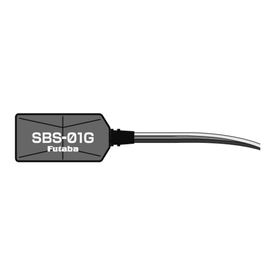
Telemetry GPS sensor
SBS-01G
Instruction Manual
Thank you for purchasing Futaba's
SBS-01G GPS sensor. This sensor, used
in conjunction with a telemetry enabled
transmitter/receiver, is used to indicate
the distance/speed/altitude of the item
to which it is attached. To maximize
your enjoyment, and to ensure proper
sensing, please read through this manual
thoroughly. We also encourage you to
retain the manual for future reference
should the need arise.
● The SBS-01G is designed for
use with Futaba telemetry systems.
SBS-01G
LED Indication
Green
Normal operation
Green blink
GPS un-receiving
Red
No signal reception
Green/Red
When setting up the slot
Green/Red
Unrecoverable error
Alternate blink
Location
SBS-01G computes position and speed
from GPS. It is not recommended to be
used in an indoor flying environment.
Moreover, it may not be able to the
flight posture of a model (inverted
e t c . ) . T h i s s e n s o r c a l c u l a t e s t h e
altitude from atmospheric pressure
a n d t e m p e r a t u r e . A t m o s p h e r i c
pressure will get lower as you go up
in altitude, using this the sensor will
estimate the altitude. An exact display
cannot be performed if atmospheric
pressure and temperature changes
a weather. A short time is required
until the positioning of the GPS is
established. In the meantime, don't
move the model during this process.
Use : GPS/Altitude sensor (from atmospheric
pressure) with Vario meter
Range:[Speed] About 0km/h~500km/h (~311mph)
[Altitude] About -700m~+5,500m
(-766yard~+6015yard) ---sensor spec
[Vario meter] About -150m/s~+150m/s
(-336mph~+336mph)
Length:175mm
Weight:11g
Voltage : DC 3.7V 〜 DC 7.4V
Wiring
T h e S B S -01G m a y o n l y b e u s e d w i t h
telemetry enabled receivers that offer
S.BUS 2 port. Please refer to the manual(s)
that accompanied your transmitter and/or
receiver for proper connection methodology.
Relative distance/altitude
Data when a power supply is turned on shall
be 0m, and it displays the distance/altitude
which changed from there.
Even if the altitude of your airfield is high, it
will start at 0m and the altitude difference
from the airfield is displayed.
Accuracy
A l i t t l e i n a c c u r a c y i s s h o w n i n
t h e d i s p l a y o f d i s t a n c e o r s p e e d .
Even if the model started at 0m returns to the
same place, it may not be displayed as 0 m.
Mounting Precautions
Do not install in a location where the wind/
air flow can hit the sensor. Also, do not put
in a sealed location where atmospheric
pressure will not change in a sealed location.
Moreover, the thing which interrupts an
electric wave must not be above a sensor
(metal, carbon).
Metal/C
Metal/Carbon
Wind
FUTABA CORPORATION
oak kandakajicho 8F 3-4 Kandakajicho, Chiyoda-ku, Tokyo 101-0045, Japan
TEL: +81-3-4316-4820, FAX: +81-3-4316-4823
WARNING
Failure to follow these safety precautions
may result in severe injury to yourself and
others.
To utilize the SBS-01G GPS sen-
sor, connect it to the S.BUS2 port of
the Futaba telemetry enabled receiv-
ers.
・ The SBS-01G will not function properly if
connected to an S.BUS port or other channel
ports.
Ensure that the unit is connected
properly to the receiver. Failure to do
so could result in damage to the sen-
sor.
Do not use the SBS-01G with any-
thing other than an R/C model.
Ensure that the unit is mounted in
an area that will eliminate exposure
to fuel, water and vibration.
・ As with any electronic components, proper
precautions are urged to prolong the life and
increase the performance of the SBS-01G.
To ensure that the SBS-01G is
functioning as desired, please test
accordingly.
・
Allow a slight amount of slack in
the SBS-01G cables and fasten them
at a suitable location to prevent any
damage from vibration during flight.
Slot number setup
Please note that the proper default
slot for this accessory is number 8 (8-
15). This sensor uses eight slots. Being
made to a start slot are 8, 16, and 24.
Information on how to change the
slot assignment is included in the
transmitter's manual.
ID number
There is an ID number in SBS-01G. ID
will be unnecessary if one GPS sensor
is carried in a model. ID is needed if
there is a schedule which carries two
or more GPS sensors in one set of on
model. However, the ID number is
indicated at the bottom of SBS-01G.
Speed alarm precaution
Since the GPS speed sensor displays
the ground speed, it cannot be used
as a stall alarm. For example, an
aircraft that stalls at 50km/h will stall
if the tailwind is 5km/h or greater
even through 55km/h is displayed
by ground speed. In addition, with
an aircraft that will disintegrate in
midflight at 400km/h at an over-speed
alarm, when the headwind reaches
30km/h the airplane will disintegrate
in midair due to over speeding even
at a ground speed of 370km/h.
©FUTABA CORPORATION
2018, 5 (3)
Advertisement
Table of Contents


Need help?
Do you have a question about the SBS-01G and is the answer not in the manual?
Questions and answers