FUTABA GY701 Quick Start Manual
Avcs gyro and head speed governor
Hide thumbs
Also See for GY701:
- Installation instructions manual (79 pages) ,
- Instruction manual (42 pages)
Advertisement
Quick Links
Advertisement

Subscribe to Our Youtube Channel
Related Manuals for FUTABA GY701


Summary of Contents for FUTABA GY701
- Page 1 UICK TART 1M23N23902...
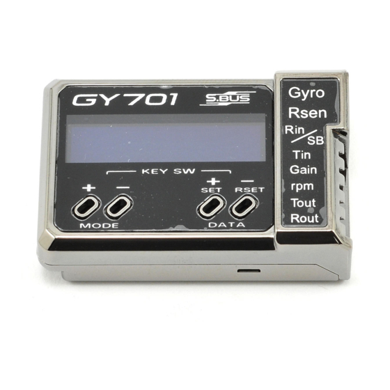
- Page 2 NTRODUCTION ® The Futaba GY701 is a heading hold AVCS gyro and head speed governor in one box. Its cutting-edge MEMS (Micro Electro Mechanical System) sensor design, ultra high-speed processing and advanced PID control algorithm put it a quantum leap ahead of all other heading hold gyros in size, weight and performance.
-
Page 3: Troubleshooting
ODEL REPARATION Prepare your model by installing the servos, receiver and power system. Leave the servo arm off of the tail rotor servo and do not connect the tail rotor servo to the GY701 until you have completed the setup later in this guide. - Page 4 ENSOR NSTALLATION 2. Electromagnetic interference could affect the gyro or tail rotor servo. Mount the gyro in a different location, away from the electronic speed control, servos and drive motor. 3. The trouble may be caused by vibration. Verify that your helicopter’s components are balanced.
- Page 5 [Gain] connection. To determine the appropriate receiver channels, please check your transmitter’s instruction manual. If using a Futaba S.Bus receiver, then only one extension is needed between the S.Bus Receiver connection and the GY701 [SB] connection. If any other information is needed please see the “S.Bus Basic Setting”...
- Page 6 ONTROL NSTALLATION Using wire mounts, wiring fi xtures molded into the helicopter, or hook and loop material, route the extensions to the receiver. Ensure that the extensions leading to the receiver cannot become entangled in rotating components and make sure the extensions are not rubbing against metal or carbon fi...
- Page 7 TRUCTURE Push DATA Push MODE +/– key +/– key Max. revolution Home Engine runtime screen OLED display mode LED display mode Operation mode Gyro Expert Gyro Basic Governor Expert Governor Basic S.Bus Basic Push MODE +/– key for 1 second From the home screen the mode [+] and [–] button will take you through the various status screens for the gyro or governor.
-
Page 8: Enu Structure
TRUCTURE From the home screen the data [+] and [–] button will navigate the upper menus which include the Home screen, Gyro Basic, Governor Basic and S.Bus Basic menus. Once the menu you would like to enter is selected (for example Gyro Basic), simply press the mode [+] or [–] button to navigate the options. - Page 9 GY701 S ETUP be reset to the defaults and the screen will change to “Exec.—“ to confi rm that the gyro has been reset. Cycle the receiver power and allow the gyro to initialize. To disable the governor, press the mode [+] button until “Opr.Mode Gyro+Gov”...
- Page 10 TRUCTURE WARNING The servo type parameter must match the type of servo you are using. Incorrect setting may damage the GY701 or the servo, possibly resulting in a loss of control during flight. Turn the receiver and transmitter power off for now. OTOR ERVO NSTALLATION...
- Page 11 OTOR ERVO NSTALLATION onto the servo ensuring that it is perpendicular to the tail rotor pushrod. Install the servo arm screw. 13.25 −16.5 mm (Depending on T/R linkage geometry) Carefully hold the tail rotor pushrod ball link onto the servo arm and verify that the tail rotor operation matches the transmitter stick input.
- Page 12 OTOR ERVO NSTALLATION WARNING Verify that the gyro compensates in the cor- rect direction before flight. If the compensation direction is incorrect the model will pirouette uncontrollably, at a very high rate. Next we need to set the servo limits within the gyro to ensure the tail rotor servo does not travel too far, causing binding.
- Page 13 ELECTING THE LIGHT Press the mode [+] key until “FLT.mode” is displayed on the screen. It is recommended that you start with the 3D fl ight mode even for beginners. The 3D mode offers a higher pirouette rate and better pirouette consistency.
- Page 14 INISHING Ensure that all extensions and servo wires are attached and bundled within the helicopter and that everything is plugged in correctly. Before the test fl ight verify all settings and ensure that the gyro compensates the proper direction. Ensure that: ❑...
- Page 15 INISHING WARNING Always make small (1%) adjustments to the tail rotor D/R or EPA once the value exceeds 100%. Over 100%, it is possible to exceed the sensor’s Angular Velocity Sensing Range (+/- 1,200° per second). The gyro will then no longer control the pirouette rate or consistency.
- Page 16 INISHING The tail rotor ratio, tail rotor pitch range and tail blade length play a large part in achieving optimum tail rotor performance. The gain value can vary drastically from model to model and the exact value should not play a part in the evaluation of the gyro’s performance.
Need help?
Do you have a question about the GY701 and is the answer not in the manual?
Questions and answers