Advertisement
Quick Links
Push button UP 233+IR, 1-fold
Push button UP 234+IR, 2-fold
Push button UP 235+IR, 4-fold
- with infrared receiver
Issued: September 2002
Operating and mounting instructions
Product
Push button 1-fold + IR
Push button 2-fold + IR
Push button 4-fold + IR
Frame
Bus coupling unit
C5
C6
C4
C3
C7
C5
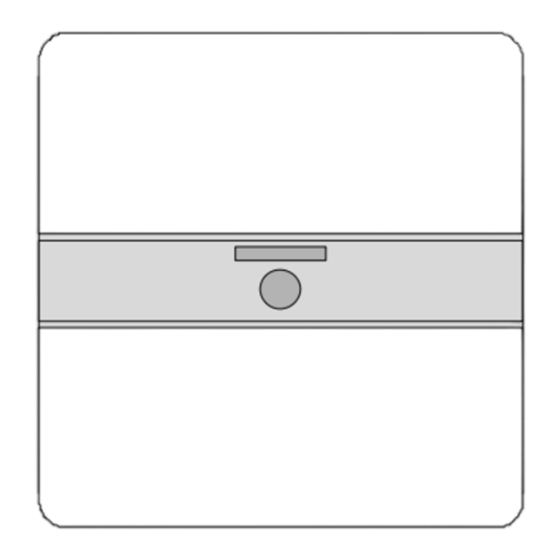
Diagram 1: Push button UP with infrared receiver
Product and functional description
The device push button 1; 2; 4-fold + IR is composed of 2 func-
tional units: the push button and the infrared receiver.
• push button
There is an upper and a lower operating field on the push but-
tons. In the middle of the push button there is a note panel in
which pictograms can be inserted. This panel also contains dis-
play elements (LEDs) for orientation lighting and also for status
displays. Opposing rockers are combined to form a pair e.g. for
defined switching, dimming, controlling shutters and blinds. It is
also possible to carry out the switching functions ON and OFF
e.g. via a push button "UP".
• infrared (IR) receiver
The IR receiving lens is incorporated in the note panel in the
middle of the push button. Thus for carrying out the functions
direct telegrams can also be transmitted onto the bus by IR
signals, sent by a hand-held transmitter S 425 and/or a wall-
mounted transmitter UP 420/421/422.
Using an application program, the push buttons UP + IR give
commands via the flush-mounted bus coupler for example to
actuators for defined switching on/off, for dimming lamps, rais-
ing/lowering shutters or for louvre adjustment or other parame-
terisable functional units.
The device push buttons + IR is placed together with the rele-
vant DELTA frame on the flush-mounted bus coupler and can
only function in combination with the bus coupler UP 114 and
an appropriate application program, i.e. the push buttons (with
bus coupler UP 114) consist of the devices (hardware) and the
application programs (software).
The bus coupler UP 114 and the relevant frame are not supplied
with the device but must be ordered separately.
Using the ETS program (EIB Tool Software), the application
programs can be selected and the specific parameters and ad-
dresses can be assigned.
GB
5WG1 233-2AB_1 Push button UP 285+IR, 1-fold 5WG1 285-2EB_1
5WG1 234-2AB_1 Push button UP 286+IR, 2-fold 5WG1 286-2EB_1
5WG1 235-2AB_1 Push button UP 287+IR, 4-fold 5WG1 287-2EB_1
DELTA profil
pearl grey
titanium white
anthracite
silver
pearl grey
titanium white
anthracite
silver
pearl grey
titanium white
anthracite
silver
C5
C6
C4
C5
C3
C7
C6
C5
Application programs
see Siemens product database from version H onward
or:
http://www.siemens.de/installationstechnik
Technical data
Power supply
Via the flush-mounted bus coupler
Operating elements
• 1, 2 or 4 pairs of rockers
The pairs of rockers are interlocked via software so that mal-
functions are not triggered when they are operated simulta-
neously.
• Number of switching cycles: > 20,000
Display elements
• Per pair of push buttons
1 LED red for status display e.g. 4fold-push buttons =
4 LED red. The parameter for a red LED can be set to "flash-
ing" if a proper incoming IR telegram is received / recog-
nised. Each LED can be parameterised for status
display or as an orientation light.
IR receiver
• Range of infrared beam: approx. 25 m if the following
conditions are met:
- with IR hand-held transmitter AP 425
(5WG1 425-7AB2)
- directed at the optical main axis,
- with 500 lux of diffuse daylight at the receiver
• Device without pictogram strips
Connections
10-pole plug connector (PEI): for connection to the flush-
mounted bus coupler
5WG1 233-2AB01
5WG1 233-2AB11
5WG1 233-2AB21
5WG1 233-2AB71
5WG1 234-2AB01
5WG1 234-2AB11
5WG1 234-2AB21
5WG1 234-2AB71
5WG1 235-2AB01
5WG1 235-2AB11
5WG1 235-2AB21
5WG1 235-2AB71
ordered separately from the DELTA ranges
cut-out frames
C1
C2
C1 Bus coupling unit
C2 Frame
C3 Fixing screws *)
C4 Basic push button module *)
C5 Rockers *)
C6 Mounting rack *)
C7 Recess *)
*) Scope of supply
C4
C3
C7
C5
DELTA style
titanium white
basalt black
titanium white metallic silver
basalt black metallic silver
titanium white
basalt black
titanium white metallic silver
basalt black metallic silver
titanium white
basalt black
titanium white metallic silver
basalt black metallic silver
____
UP 114
Mechanical data
• Housing: plastic
• Dimensions:
- DELTA profil (L x W x D): 65 x 65 x 10 mm
- DELTA style (L x W x D ): 68 x 68 x 14 mm
• Weight: approx. 55 g
• Fire load: approx. 950 kJ ± 10 %
• Mounting: placed on the flush-mounted bus coupler
Electrical safety
• Degree of pollution (according to IEC 60664-2): 2
• Type of protection (according to EN 60529): IP 20
• Protection class (according to IEC 60536): III
• Overvoltage category (according to IEC 60664-1): III
• Bus: safety extra-low voltage SELV DC 24 V
• Device complies with EN 50090-2-2 and IEC 60664-1: 1992
Reliability
Normal service life: 10 years
EMC requirements
complies with EN 50081-1, EN 61000-6-2 and EN 50090-2-2
Environmental conditions
• Climatic withstand capability: EN 50090-2-2
• Ambient operating temperature: - 5 ... + 45 °C
• Storage temperature: - 25 ... + 70 °C
• Relative humidity (not condensing): 5 % to 93 %
Approval
EIB-certified
CE mark
in accordance with the EMC guideline (residential and
functional buildings) and the low voltage guideline
1 / 2
5WG1 285-2EB11
5WG1 285-2EB21
5WG1 285-2EB81
5WG1 285-2EB01
5WG1 286-2EB11
5WG1 286-2EB21
5WG1 286-2EB81
5WG1 286-2EB01
5WG1 287-2EB11
5WG1 287-2EB21
5WG1 287-2EB81
5WG1 287-2EB01
Please turn over !
Advertisement

Related Manuals for Siemens 5WG1 233-2AB01


Summary of Contents for Siemens 5WG1 233-2AB01
- Page 1 • Dimensions: The device push button 1; 2; 4-fold + IR is composed of 2 func- see Siemens product database from version H onward - DELTA profil (L x W x D): 65 x 65 x 10 mm tional units: the push button and the infrared receiver.
- Page 2 • The device may not be opened. module (C4). • Any faulty devices should be returned to the local Siemens office. DELTA profil • Insert the screwdriver into the slot (A2) until it reaches the stop and then wiggle it.