Table of Contents
Advertisement
Quick Links
Advertisement
Table of Contents

Related Manuals for ISOMAG CS3820


Summary of Contents for ISOMAG CS3820
- Page 1 OPERATING AND MAINTENANCE MANUAL CS3820 3820_IT_EN_R2_1.00.0000...
- Page 2 Release number: 3820_IT_EN_R2_1.00.0000 The characters of file name in bold type indicate the software version which the manual refers to; it is visualized at the instrument start up, or by specific function on DIAGNOSTIC menu. The reproduction of this manual and any supplied software is strictly forbidden.
- Page 3 3820_IT_EN_R2_1.00.0000...
-
Page 4: Table Of Contents
DATA PLATE ___________________________________________________________ 7 SHREWDNESS AND PRECAUTIONS _________________________________________ 8 INSTALLATION IN PRESSURIZED PIPE ______________________________________ 9 CONVERTER SETTING __________________________________________________ 10 CS3820: PRESSURE SENSOR INSTALLATION _________________________________ 11 TECHNICAL CHARACTERISTICS __________________________________________ 11 MAXIMUM ALLOWED SPEED _____________________________________________ 12 MEASURE CONSUMPTIONS ______________________________________________ 13 ELECTRICAL CONNECTIONS INPUT/ OUTPUT ________________________________ 14... - Page 5 MENU 3 - SCALE _______________________________________________________ 33 MENU 4 - MEASURE ____________________________________________________ 35 MENU 5 - ALARMS _____________________________________________________ 37 MENU 6 - INPUTS ______________________________________________________ 38 MENU 7 - OUTPUTS ____________________________________________________ 39 MENU 9 - DISPLAY _____________________________________________________ 40 MENU 10 - DATA LOGGER _______________________________________________ 41 MENU 11 - FUNCTION __________________________________________________ 48 MENU 12 - DIAGNOSTIC ________________________________________________ 49 MENU 13 - SYSTEM ____________________________________________________ 51...
-
Page 6: Safety Information
INTRODUCTION ‰ These operating instructions and description of device functions are provided as part of the scope of supply. ‰ They could be modified without prior notice. The improper use, possible tampering of the instrument or parts of it and substitutions of any components not original, renders the warranty automatically void. ‰... -
Page 7: Safety Convention
‰ The specialists must have read and understood these Operating Instructions and must follow the instructions it contains. The Operating Instructions provide detailed information about the device. If you are unclear on anything in these Operating Instructions, you must call the ISOIL service department. ‰... -
Page 8: Overall Dimensions
OVERALL DIMENSIONS 207.0 114.0 Alignment handle it could be unscrew after use SIZE 1060 1360 2360 346.0 3820_IT_EN_R2_1.00.0000 5 di 69... -
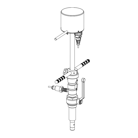
Page 9: Cs3820 Layout
CS3820 LAYOUT View A View A POS. DESCRIPTION POLISHED COVER ORING 3500 STAINLESS SCREW M3x8 ALIGNMENT HANDLE PUSH HANDLE FIXING KNOB PRESSURE SENSOR QUICK CONN. GRUB SCREW M10X12 1”JACKET 1” VALVE SAFETY CHAIN CONN. 62GB-57A-08-04PN (METAL) CAP 62GB-814-08 (METAL) CONN. -
Page 10: General Information The Sensor
GENERAL INFORMATION THE SENSOR Before install the sensor locate the direction of the liquid in the piping The sign of the flow rate is positive, when the flow direction it’s from – to + as printed on the tag plate. If after the installation, for plant request becomes necessary reverse the sign of the flow, it's enough reverse the sign of the coefficient KA. -
Page 11: Shrewdness And Precautions
SHREWDNESS AND PRECAUTIONS In vertical installations an ascending flow is preferable. For vertical installations with descending flow direction contact the manufacturer Avoid a partially empty pipe, during operation the pipe must be either completely full of liquid or completely empty Install the sensor away from bends and hydraulic accessories SEE TABLE 5 X DN... -
Page 12: Installation In Pressurized Pipe
INSTALLATION IN PRESSURIZED PIPE 1) Define and block on Z value the reference ring PIC.1 (pic. 1) AVAILABLE INSERTION DEEP Insertion “Z” VALUE 1/8D Z=L-(X+S+1/8D+92) 1/2D Z=L-(X+S+1/2D+92) REFERENCE RING 7/8D Z=L-(X+S+7/8D+92) N.B.: for other dimensions see complete layout on next page Fig.2 2) Weld to the pipeline the Ø... -
Page 13: Converter Setting
PUSH HANDLE REFERENCE RING SENSOR SIZE MAX DEPTH SIZE 0 150 (X<140) SIZE 1 300 (X<140) JACKET 1" SIZE 2 500 (X<140) SIZE 3 1060 700 (X<140) SIZE 4 1360 1000 (X<140) VALVE 1" SIZE 5 2360 2000 (X<140) 1/8D PIPE LINE 1/2D... -
Page 14: Cs3820: Pressure Sensor Installation
TECHNICAL CHARACTERISTICS lEctrical charactEristics Classification of the instrument: class I, IP 68, category of installation II Power supply Power supply Power supply version voltage frequency power Current LITIUM 3,6 V – 16,5 A/h BATTERY nput output isolation ‰ Input/output are insulated up to 500V ‰... -
Page 15: Maximum Allowed Speed
M A X I M U M A L L O W E D S P E E D WARNING! The insertion and extraction operations of the insertion instruments are operations that can be dangerous when working with the pressure tube. The pressure inside the tube apply a significant force on the probe that can be ejected violently, creating dangerous situations for the operators. -
Page 16: Measure Consumptions
MEASURE CONSUMPTIONS The batteries consumption depends from the setting of the measure profile (sampling interval) and the frequency of the digital outputs. B1-B2 BATTERIES STANDBY MODE B1/B2 B1/B2 MEDIUM HIGH CONSUMPTION CONSUMPTION CONSUMPTION 3820_IT_EN_R2_1.00.0000 13 di 69... -
Page 17: Electrical Connections Input/ Output
ELECTRICAL CONNECTIONS INPUT/ OUTPUT OPTIONAL: Plug female Mil connector (with or without 5m of cable) Male Mil connector Input A: DIGITAL INPUTS B: OUTPUTS COMMON IN/OUT common C: OUT 1 D: OUT 2 Output 1 Output 2 lEctrical diagram outputs OUT 1 = (Connector pin C) OUT 2 = (Connector pin D) 40 V... -
Page 18: Grounding Connection
GROUNDING CONNECTION For correct operation of the meter is NECESSARY that the sensor and the liquid are equipotential, so ALWAYS connect the sensor and converter to ground. For grounding with cathode protection pipe contact the manufacturer. 3820_IT_EN_R2_1.00.0000 15 di 69... -
Page 19: Electrical Connections
ELECTRICAL CONNECTIONS *sh = shiEld of caBlE intErnally connEctEd to ground COILS OUTPUTS OUT 1 OUT 2 ELECTRODES COM OUT/IN INPUT BATTERY CONNECTIONS Batteries Socket for battery 1 Socket battery 2 3820_IT_EN_R2_1.00.0000 16 di 69... -
Page 20: User Interface
USER INTERFACE CS3820 can be programmed by MCP interface (USB cable is required see below) Make the USB connection as shown in the following picture. Conn. IP68 USB type B Plug IP68 USB type B USB type A 3820_IT_EN_R2_1.00.0000... -
Page 21: Meaning Of Flags
mEaning of flags FLAG DESCRIPTION FLAG DESCRIPTION EMPTY PIPE MIN FLOW ALARM FILE UPLOAD MAX FLOW ALARM FILE DOWNLOAD VIDEO TERMINAL CONNECTED LOW BATTERY FLOW RATE OVERFLOW LOW BATTERY PULSE 1 OVERFLOW FLOW RATE SIMULATION (FLASHING) PULSE 2 OVERFLOW GENERAL ALARM ONLY ON PHYSICAL CALIBRATION (FLASHING) - Page 22 START VISUALIZATION PAGES The visualization pages can be change according to instrument’s setup. Electrode 2 voltage Electrode 1 voltage Electrode 2 resistance Video term. connected Electrode 1 resistance Flow speed % full scale Flow rate graph Flow rate value Flow rate trand Partial net totalizer Data &...
-
Page 23: Flow Rate Visualization
FLOW RATE VISUALIZATION This symbol appears only when the overall noise is over 2.5% of flow rate. The converter of the meter can show a 5 digits display for flow rate units; this mean the maximum flow rate value that can be represented on the display is 99999 (no matter the positioning of the decimal point). -
Page 24: Access Code Set : Menu 13 System
CONVERTER ACCESS CODE The access for programming the instrument is regulated by six access levels logically grouped. Every level is protected by a different code. ‰ Access Level 1-2-3-4 Freely programmable by user 13 s ccEss ystEm Depending on the level of access different display functions will be visible. - Page 25 The following example shows how to change the Full scale by Quick Start menu; the second illustrates how to change the function by the Main menu. EXAMPLE: modifying the full scale value from 0.4L/s to 0.5L/s, from the “Quick start menu” Press enter key to access in the Use the right-left arrow keys to select the character and “Quick Start menu”...
- Page 26 EXAMPLE: modifying the full scale value from 0.4l/s to 0.5l/s, from the “Main Menu” (quick start menu enabled) Press enter key to access in the Use the right-left arrow keys to select the character “Quick Start menu” and the up-down arrow key to assign the numeric value of the access code Press the enter key to confirm the access code Select the Main Menu function with the arrow keys...
-
Page 27: Functions Menu
FUNCTIONS MENU The main menu is selected from the Quick start menu by pressing enter in your key board and entering the access code. Note: Functions in grey here below are displayed only with other functions active, or with optional modules. Sensors model: Enter the first two characters of the serial number of the probe Flow sensor lining material type Type of sensor: fullbore or insertion... - Page 28 5.1 Maximum value alarm set for direct flow rate 5.2 Maximum value alarm set for reverse flow rate 5.3 Minimum value alarm set for direct flow rate 5.4 Minimum value alarm set for reverse flow rate 5.5 Hysteresis threshold set for the minimum and maximum flow rate alarms 6.1 Total direct (positive) flow totalizer reset enable 6.2 Partial direct (positive) flow totalizer reset enable 6.3 Total reverse (negative) flow totalizer reset enable...
- Page 29 10.1 Data logger enable 10.2 Measure unit recording enable 10.3 Field separator character 10.4 Decimal separator character 10.5 Sampling interval 10.6 Enable logging of total direct totalizer 10.7 Enable logging of partial direct totalizer 10.8 Enable logging of total reverse totalizer 10.9 Enable logging of partial reverse totalizer 10.10...
-
Page 30: Functions Description
FUNCTIONS DESCRIPTION Here below the explanation on how the rows of menu are described. Menu visualized on the converter (from 1 to 13) MENU 1 - SENSOR Sensor Model (POS. 1.1) [S. model xxx] [SMODL] Access level MCP command Convert request1 Synthetic description of the function The following picture describes where to find the name of the MCP functions in MCP-software. -
Page 31: Menu 1 - Sensor
MENU 1 - SENSOR Sensor model (POS. 1.1) [S. model xxx] [SMODL] Enter the first two characters of the serial number of the sensor as on the sensor label. Lining Type (POS. 1.2) [Lining= UNSPEC.] [LIMAT] Flow sensor lining material type. (PFA; PU-TDI; ALON; PEEK; HR; PP; PA-11; PTFE-HT; PTFE) Type of sensor (POS. - Page 32 (POS. 1.14) [KC= +/- xx.xxx] [CFFKC] Calibration Factor. This function is activated if the sensor model is NOT present on the sensors table standard parameters Coils Ex.Current (POS. 1.15) [C.Curr.= mA xxx.x] [CEXCC] Excitation coils current. This function is activated if the sensor model is NOT present on the sensors table standard parameters.
- Page 33 MENU 1 - SENSOR: ONLY MCP FUNCTIONS Sensor Coils Time A [MCP ONLY] [SCTMA] Reference sensor coil time A Sensor Coils Time B [MCP ONLY] [SCTMB] Reference sensor coil time B Sensor Coils Resistance [MCP ONLY] [SCRES] Reference sensor coil resistance Resistance E1 [MCP ONLY] [SE1RR]...
-
Page 34: Menu 2 - Units
MENU 2 - UNITS WARNING: The totalizer value is updated and changed depending on the setting of unit value. The scale change may cause accuracy loss depending of rounding up. For example, if T +=0,234 liters with 3 decimals, it become T +=0.001 m³ losing 0.234 liters in rounding up. Diameter (POS. - Page 35 Part direct Dec. Point pos. (POS. 2.11) Total. [P+ D.P.= x] [TPPDP] Setting partial direct totalizer decimal point position. Example: P+D.P.= 3 visualized value P+dm³ 0.000 / P+D.P.= 2 visualized value P+dm³ 0.00 Total. T reverse unit of m. type (POS.
-
Page 36: Menu 3 - Scale
MENU 3 - SCALE Flow Rate Full Scale 1 (POS. 3.1) [FS1= l/s xxxx.x] [FRFS1] The full scale is used to indicate to the maximum meter’s flow rate; a volume per time is required. The full scale should be chosen carefully as it’s parameters are used for several other parameters. There are three fields to fill in order to set this parameter, from left to right: 1) measure unit, 2) time unit of measure and 3) numeric value. - Page 37 Pulse 1-2 (POS. 3.2-3.4)Output [Pls1-2= dm³ x.xxxxx] [OP1PV-OP2PV] Pls1 and Pls2 is active with POS.”7.1 Output 1 functions” page 25-”7.2 Output 2 functions” page enable and setting pulse value on channel 1 and channel 2. This function allows the user to set a signal (a pulse) to be given from the converter when a defined amount of liquid has passed through the sensor.
-
Page 38: Menu 4 - Measure
MENU 4 - MEASURE Measure (POS. 4.1) [M. Prof.=C.PWR/SMART1/2/5] [MFDMP] This section of manual is important because the correct setting of the filters allows to get a proper instrument’s behaviour according to the specific requirements of use. ∆ v FlowRate Measure Di erential Speed... - Page 39 Cut-off threshold (POS. 4.2) [Cut-off=% xxx] [MFCUT] Setting the low flow cutoff threshold. This function is useful to avoid that flows close to zero, due to the electrical noises from tiny movements of liquid (due for example to vibrations of the pipe) which cause an increasing of the totalizers.
-
Page 40: Menu 5 - Alarms
MENU 5 - ALARMS Maximum direct flow rate threshold (POS. 5.1) [Max. thr+=% XXX] [FRAXP] Maximum value alarm set for direct flow rate set. When the flow rate value exceeds such a threshold, then an alarm message is generated. The value of this parameter is expressed as percentage of the full scale value and may be set from 0 to 125%. -
Page 41: Menu 6 - Inputs
MENU 6 - INPUTS T. direct (pos.) flow tot. /part reset enable (POS. 6.1-2) [T/P+/RESET=ON/OFF] [VTTPE] [VTPPE] When one of this function is enabled, the related totalizer + may be reset through the on/off input. T. direct (neg) flow tot. /part reset enable (POS. -
Page 42: Menu 7 - Outputs
MENU 7 - OUTPUTS Output 1 function selection (POS. 7.1) [Out1=XXXXXX] [OUT1F] Function choice corresponding to digital Output 1. The functions are listed in the table below. Output 2 function selection (POS. 7.2) [Out2=XXXXXX] [OUT2F] Function choice corresponding to digital Output 2. The functions are listed in the table below. FUNCTIONS FOR OUTPUTS 1 AND 2 ‰... -
Page 43: Menu 9 - Display
MENU 9 - DISPLAY Language for all msn (POS. 9.1) [Language= ITA/EN] [LLANG] Choice of the language. There are 2 languages available: EN = english, IT = Italian. KeyBoard Timeout Time (POS. 9.2) [Disp. time=s xxx] [KBTMT] This function set dispay/keyboard inactivity. The set values are from 020 to 255 second. Partial totalizer (POS. -
Page 44: Menu 10 - Data Logger
MENU 10 - DATA LOGGER Data logger enable (POS. 10.1) [D.logger en= /OFF] [DLOGE] This function enables data loger. The following functions are activated by [D.loger en= Measure (POS. 10.2) Unite of [Meas. units= ON] [DLUME] Measure unit recording enable Field separator character (POS. - Page 45 Sensor test result (POS. 10.15) [Log STR= ON] [DSTRE] Enable logging of sensor test results Board temperatures (POS. 10.16) [Log BTS= ON] [DBTSE] Enable logging of board temperature Internal board voltages (POS. 10.17) [Log IBV= ON] [DIBVE] Enable logging of internal board voltage Electrodes DC voltages (POS.
- Page 46 USING DATA LOGGER BY MCP INTERFACE Data are stored on micro SD card; the organization is based on “tree-structure”: the system create a daily folder where it save events and data logger . The data can be downloaded by MCP interface. MCP INTERFACE Click tab-control data logger to view files.
- Page 47 C=Today Last; this option allows to download the latest files, recordered after the laat download All; this option allows the download of all the current day of the file D=Save path: This option allows you to save files to the folder on your PC E=Download: Button to start the download process F=Stop:...
- Page 48 View downloaded files setting download data logger. Note: The fields are in a fixed position, regardless if the above fields are active or not. The disabled fields are empty (delimited by the separator but without data). N°Record. View progressively the number of registered records. Date.
- Page 49 Voltage measured on electrode E1. Form fields when is active the recording of data on the input voltage (diagnostic value). Voltage measured on electrode E2. Form fields when is active the recording of data on the input voltage (diagnostic value). Differential voltage between the two electrodes.
- Page 50 Example: Sensor Verify The function “Sensor Verify” creates the “STESTLOG.CSV” file, according to the following conditions: 1) Activate the SDC / RTC option in group “HW Config” (by factory see the order code) 2) Activate the “BIV” in the group “PRODUCT CODE” (by factory see the order code) 3) Activate the “Sens.verify”...
-
Page 51: Menu 11 - Function
MENU 11 - FUNCTION The following functions are activated by first pressing the “ENTER” and then the “ESC” when the screen appears “confirm” to start the function. Totalizer Total Positive reset (POS. 11.1) [T+ RESET= ON] [VTTPR] Reset total direct totalizer for direct flow rate (+) Totalizer Par. -
Page 52: Menu 12 - Diagnostic
MENU 12 - DIAGNOSTIC Self Test Diagnostic (POS. 12.1) [Self Test] [ATSIC] Meter auto-test function. This function stops the normal functions of the meter and performs a complete test cycle on the measure input circuits and on the excitation generator. To activate this function, after select it, push key Enter, at the question: “CONFIRM EXEC.?”... - Page 53 Following are the states for the PPP link and MCPI to connect the device. PPP link status: “UNDT” = undetermined “DEAD” = dead, link down, persistent condition “LCP” = LCP phase, transition condition “AUTH” = Authentication phase, transition condition “IPCP”...
-
Page 54: Menu 13 - System
Firmware info (POS. 12.7) [Firmware info] MODSV Firmware info version/revision Board Serial Number (POS. 12.8) [ S/N= xxxxxx ] [SRNUM?] View Board serial number. (read only) Working Time (POS. 12.9) [ WT= xxxx: xx: xx: xx ] [TWKTM?] View Total working time instrument. (read only) MENU 12 - DIAGNOSTIC: ONLY MCP FUNCTIONS Diagnostic Function [MCP ONLY]... - Page 55 IP ADDRESS SETTING (13.12-13-14) (POS. 13.12)Device IP address [XXX.XXX.XXX.XXX] [DIPAD] Device IP network edress (POS. 13.13) Client IP address [XXX.XXX.XXX.XXX] [CIPAD] Client IP network adress (POS. 13.14) Network mask [XXX.XXX.XXX.XXX] [NETMS] Network mask. Caution: Changes to the functions of the points 13.12-13.13-13.14 are enabled after the drive device restart (see function 12.1 Self test for restart converter).
- Page 56 MENU 13 - SYSTEM: ONLY MCP FUNCTIONS Unique Identity KEY [MCP ONLY] [UIKEY] Device Unique Identity key HardWare SET [MCP ONLY] [HWSET] Device hardware configuration HardWare CODe [MCP ONLY] [HWCOD] Device hardware code Calibr. Exec. status Memory [MCP ONLY] [CALXM] Calibration Execution status Memory.
- Page 57 Access CODE [MCP ONLY] [ACODE] Input the right access code Exemple set quick start menù function for mcp. ACODE=0;FCODS=[MCP COMMAND];QSFNS=1 Access Code INSERT MCP Command Quick Start FuNction Selection of the function to be activated in the QS menu. LINK Terminate [MCP ONLY] [LTERM]...
- Page 58 Volume Totalizer Total Negative Set [MCP ONLY] [VTTNS] Totaliz.T- value set Volume Totalizer Partial Negative Set [MCP ONLY] [VTPNS] Totaliz.P- value set Volume Total Positive Overflow Set [MCP ONLY] [VTPOS] Totaliz.T+ overflow value set Volume Partial Positive Overflow Set [MCP ONLY] [VPPOS] Totaliz.P+ overflow value set...
-
Page 59: Menu 14 - File (Only Mcp)
MENU 14 - FILE (ONLY MCP) File Transfer ABoRt [MCP ONLY] [FTABR] Abort the current File Transfer File Transfer STAte [MCP ONLY] [FTSTA] Show the File Transfer state Read Last EVenTs [MCP ONLY] [RLEVT] Read the latest system events Read All EVenTs [MCP ONLY] [RAEVT]... -
Page 60: Menu 15 - Process Data (Only Mcp)
FuNCtion list file WRite [MCP ONLY] [FNCWR] Save the functions list to file Function Enable Status WRite [MCP ONLY] [FESWR] Save function enable status to file Quick Start function Status WRite [MCP ONLY] [QSSWR] Save quick start function enable. MENU 15 - PROCESS DATA (ONLY MCP) OUTput 1 Set [MCP ONLY]... - Page 61 Volume Totalizer Total Negative Value [MCP ONLY] [VTTNV] Totaliz.T- read value Volume Totalizer Partial Negative Value [MCP ONLY] [VTPNV] Totaliz.P- read value Volume Totalizer Total Positive Overflow [MCP ONLY] [VTTPO] Totaliz.T+ number of overflows Volume Totalizer Partial Positive Overflow [MCP ONLY] [VTPPO] Totaliz.P+ number of overflows...
-
Page 62: Battery Replacement
View system battery charge status SEQuence NumBer [MCP ONLY] [SEQNB] Sequence number BATTERY REPLACEMENT The following is listed the procedure for replacing batteries flowmeter CS3820. Disconnect the batteries to be replaced. Components to be replaced Remove the zip ties and the batteries BATTERY BATTERY... - Page 63 BATTERIES ASSEMBLY BATTERY ZIP TIE ZIP TIE SUPPORT BATTERIES ZIP TIE ZIP TIE Connect the batteries. Close the cover of the flow meter. 3820_IT_EN_R2_1.00.0000 60 di 69...
-
Page 64: Meter Data
SERIAL NUMBER. OPERATING PROCEDURE TO CHANGE THE CONVERTER BOARD Remove the 3 screws (see “CS3820 construction” page6) to remove the cover. Unplug the batteries connectors from pcb Disconnect any cable from terminal block... - Page 65 Remove the 8 screws to be Insert new board able to remove the PCB from the support board. Replace spacers from old board to the new board. Fix the 2 screw of the board support Insert in the new board the SD card earlier removed. Connect the cables to the terminals block Assemble the cover and fixit with the 3 screws Attention: not damage the cables...
-
Page 66: Velocity K-Factor Setup (Kp,Ki)
VELOCITY K-FACTOR SETUP (KP,KI) Flow rate equation: Q=KA x KP x KI x V x A , V= Velocity A=inner Area CONVERTER SENS. OPERATION INSTALLATION AT POSITION MODE AUTO KP (see table) KI EQUATION 7/8D MANUAL FLOATING 1 (EDITABLE) 1(EDITABLE) Kp Profile factor (VxD) -
Page 67: Error Code Test System Of Sensor
ERROR CODE TEST SYSTEM OF SENSOR The codes are in hexadecimal format, the meaning is given for each bit. There are several possible error simultaneous combinations (more bits active) then that will give the combined numerical codes. CODE ANOMALIES DESCRIPTION ACTION TO TAKE 0000 NO ERROR... -
Page 68: Alarm Messages (Causes And Actions To Be Taken)
ALARM MESSAGES (CAUSES AND ACTIONS TO BE TAKEN) MESSAGGIO CAUSE ACTION TO TAKE NO ALARMS All works regularly [000] SYSTEM RESTART [001] INTERNAL PS FAIL Internal supply voltage error Contact the service Set the system clock from the converter menu [002] CLOCK NOT SET System Clock not set 13 (see also MCP function ). - Page 69 At the end of its lifetime, this product shall be disposed of in full compliance with the environmental regulations of the state in which it is located. 3820_IT_EN_R2_1.00.0000 66 di 69...
-
Page 70: Manual Reviews
MANUAL REVIEWS REVIEW DATE DESCRIPTION CS3820_EN_NL_R0_1.00.0000 13/12/2017 First edition CS3820_EN_NL_R1_1.00.0000 31/01/2019 Maximum speed allowed notes added CS3820_EN_NL_R2_1.00.0000 19/02/2019 Plug mil connector added 3820_IT_EN_R2_1.00.0000 67 di 69... - Page 71 3820_IT_EN_R2_1.00.0000 68 di 69...
- Page 72 ISOIL INDUSTRIA S.p.A. HEAD OFFICE SERVICE Via Fratelli Gracchi, 27 isomagservice@isoil.it 20092 Cinisello Balsamo (MI) Tel +39 02 66027.1 Fax +39 02 6123202 sales@isoil.it If you want to find the complete list of our distributors access at the following link: http://www.isoil.com/u_vendita.asp Due to the constant technical development and improvement of its products, the manufacturer reserves the right to make changes and/or modify the information...
Need help?
Do you have a question about the CS3820 and is the answer not in the manual?
Questions and answers