
Related Manuals for INDRA Smart Series


Summary of Contents for INDRA Smart Series
- Page 1 Indra Smart Range Installation Guide Be at the forefront of EV charging with Indra’s pioneering technology...
-
Page 2: Table Of Contents
Charge Analytics Protective Earth, Simultaneous Touch (PESTs) Protection General Installation Notes Charger Layout Smart LUX™ Smart PRO Pre-Installation Survey Installation Procedure Procedure Switchgear Choosing the charger location Wall Mounting Hanging the charger Smart LUX™ storage hook Indra Smart Range Installation Guide... - Page 3 Cable Entry Smart LUX™ Smart PRO Connect Mains Cables Smart LUX™ Smart PRO Installing a Reference Pin Connectivity Wi-Fi Wi-Fi Pairing Hardwired 4G Pairing External CT Clamp Testing Continuity of Protective Conductors Insulation Resistance (IR) Polarity Earth Electrode Resistance Testing Earth Fault Loop Impedance (EFLI) Verification RCD Testing Sealing the Unit Commissioning Customer Handover Charger Familiarisation Customer Support Wire Cut Lengths...
-
Page 4: Products In The Range
Products in the Range Smart PRO Tethered Smart PRO Type 2 (SPRFGTWG102) has an IEC 62196 (Type 2) 6M tethered charging connector to be used with Type 2 socket fitted EVs. Smart PRO Untethered Smart PRO Type 2 Untethered (SPRFGSKWG103) has an 62196 (Type 2) socket as part of the front body. Indra Smart Range Installation Guide... -
Page 5: Smart Lux™ Tethered
Black Grey Stone White General Description This manual describes the method of installation and hardware operation of the Indra Smart Range, where the charger is a permanently installed electric vehicle charging solution for resistive domestic and commercial loads of at least 6A and up to 32A at 230V, 50Hz. Smart LUX™ Product Codes: SMNFGT2WH401 Indra White, 6m... -
Page 6: General Warnings And Safety
The Smart Range should be installed in accordance with the extant wiring regulations (BS7671). • Use of an upstream O-PEN protection device is NOT permitted with Indra Smart Range. Use of such devices will VOID the warranty. • Before commencing installation or maintenance, the electrical power supply MUST be safely isolated. -
Page 7: Overview And Intended Use Environment
Overview and Intended Use Environment Indra Smart Range can be classified as a ‘smart’ electric vehicle charging solution because of the communications infrastructure which allows charging to be remotely optimised by the Indra App; where charging can take place when electricity is cheapest; or if immediate charging is required, its ‘Boost’ functionality overrides any smart grid criteria and provides instantaneous charging capability. Charging using Indra Smart chargers can take place at up to 7.4kW, but due to modulation capability (measured by the external CT clamp) this power output level can also be reduced. The Smart Range are intended for both indoor and outdoor installation, securely mounted to a wall or appropriately pedestal. -
Page 8: Smart Features
It works by monitoring the amount of power the installation is using via an external CT clamp and comparing that to the rating of the main cut-out supplying the installation. If the difference is greater than 32A then the charger will offer full charge. If the difference is less than 32A then the charger will only offer as much power as there is spare capacity on the main cut-out. Note: G100.2 defines how load curtailment is managed. If the charger is configured to use load curtailment and it loses contact with the external CT clamp, then the charger will de-rate its power output to 6A to protect the main cut-out, thus 6A is the figure that should be considered when carrying out the maximum demand survey. DC Leakage Protection An RDC-DD is fitted into Indra Smart chargers, offering 6mA DC leakage protection. This means they should be installed with a Type A or type F RCD up stream. Indra Smart Range Installation Guide... -
Page 9: Tariff Intelligence
This feature enables the customer to tell the charger what electricity costs them and when, the charger will charge the car at the cheapest times. This feature is also compatible with all time of use tariffs including agile. Solar Mode This mode can be selected in the Indra App and can enable the customer to use any excess solar energy (or any other form of micro-generation) to charge their car. The external CT monitors how much energy is being exported from the installation. If the installation is exporting more than 1.4KW, then the charger will offer the car a charge. -
Page 10: Protective Earth, Simultaneous Touch (Pests) Protection
Consideration should be given to nuisance trips where the line to neutral voltage may exceed 253V, especially where local renewables are present. Mode A without reference electrode Used for installations that do not fall under the requirements of 722.411.4.1 E.g. TT installations; installations where the charger and car will be indoors when charging; installations where PME is bonded to Earth in accordance with BS7671:2018; regulation 722.411.4.1, Indent ii. Indra Smart Range Installation Guide... -
Page 12: General Installation Notes
AC electricity supply having the same voltage and current rating as shown on the product label. The chargers should be installed in accordance with extant wiring regulations. The charger MUST NOT be fitted alongside an upstream protection device which claims to meet ident (iv) of BS 7671:2018+A1:2020+A2:2022; section 722.411.4.1. Voltage upstream PEN Fault protection and curtailment devices may damage the device through frequent removal of the grid supply under load. WARNING: Protection against electric shock shall not be automatically reset. The charger MUST be connected to CPC (either supplied from a PME or TT earth). The installation location MUST be structurally sound and MUST NOT be subject to excessive dust, vibration, lint, or other material build-up which could affect the charger’s proper operation. The customer should have agreed to the position of the charger and any additional enclosures, and cable routing. Indra Smart Range Installation Guide... -
Page 13: Charger Layout
Charger Layout - Smart LUX™ CT Connections Wireless Dongle USB & RJ45 Live Neutral REF CPC PESTs Mode Switch... -
Page 14: Smart Pro
Charger Layout - Smart PRO CT Connections Wireless Dongle USB & RJ45 Live Neutral REF CPC PESTs Mode Switch Indra Smart Range Installation Guide... -
Page 15: Pre-Installation Survey
Pre-Installation Survey Before installing an Indra smart charger, we recommend surveying the installation to ensure that an install can go ahead and that the charger is appropriate for the customers’ requirements. This survey should include: • Identify the earthing arrangement of the property and the required PEST mode. • If a reference electrode will be required, identify a suitable location for it. •... -
Page 16: Installation Procedure
Inspect the charger to ensure it has not been damaged in transit and is safe to connect. Switchgear Indra smart chargers require an upstream type A or F RCD to be fitted. Indra recommend installing the following equipment upstream to minimise potential nuisance tripping and to ensure compliance with BS7671:2018 A1:2020+A2:2022 section 722. (These requirements can be met in whatever configuration suits your design). Type A 30ma Double Pole RCD protection C Curve 40A Overcurrent protection In accordance with BS 7671:2018 A1:2020+A2:2022 Regulation 443.4.1 a surge protection... -
Page 17: Choosing The Charger Location
Choosing the Charger Location • Select an installation location that ensures future servicing of the Indra Smart charger, where the back plate can be mounted flush to a flat wall and screws can be used to permanently secure the charger in position. • Make sure the install location will not allow any flammable material to come within 100mm of the unit. • The control panel of the unit should be installed between 0.75m - 1.20m from the ground. • The charger should be placed such that the potential risk of tripping over trailing charging leads is minimised as far as reasonably practicable. -
Page 18: Hanging The Charger
Figure 1: Smart LUX™ Wall Mounting Figure 2: Smart PRO Wall Mounting Smart LUX™ Storage Hook The Smart LUX™ Storage Hook should be fitted in close proximity to the charger to enable the tethered charging cable to be stowed on it. The cable hook should be secured with the supplied fixings as per Figure 3 Figure 3: Cable Storage Hook Indra Smart Range Installation Guide... -
Page 19: Cable Entry
Cable Entry - Smart LUX™ The Smart LUX™ is designed with two cable entries in the bottom edge and one in the rear (Identified in blue on Figure 4). • All cable entry points are designed for a 25mm hole. • Install a 25mm IP68 rated gland for the cable identified in the circuit design. Figure 4: Smart LUX™ Cable Entry... -
Page 20: Smart Pro
• Cable entry point 1 is designed for a 25mm hole. • Cable entry point 2 is designed for a 20mm hole. • The rear entry points are designed for a 25mm hole. • Install the appropriately sized IP68 gland for the cable used. Cable Entry 2 Cable Entry 1 Figure 5: Smart PRO Cable Entry All swarf and shavings should be removed from the charger and the hole deburred. Indra Smart Range Installation Guide... -
Page 21: Connect Mains Cables
• Insert wires into the lever type connectors labelled L (Live), N (Neutral) and CPC (Circuit Protective Conductor). Note: Indra recommend the use of bootlace ferrules on class 5 & 6 cables ONLY. Note: Indra recommend using EV Ultra Cable from Doncaster Cables as is contains power and data in the same cable. Figure 6: Smart LUX™ Mains Cable Routing... -
Page 22: Smart Pro
Connect Mains Cables - Smart PRO Note: Cut the mains wires with reference to the Wire Cut Length table. • Remove the outer insulation of the cable, leaving 10mm showing at the gland. • Route the wires as per Figure 7. • Insert wires into the lever type connectors labelled L (Live), N (Neutral) and CPC (Circuit Protective Conductor). Figure 7: Smart PRO Mains Cable Routing Indra Smart Range Installation Guide... -
Page 23: Installing A Reference Pin
Drive the pin straight into the ground, leaving enough length at its tip to secure the clamping terminal. • Attach the lug clamp terminal and run a length of cable (Indra recommend solar PV cable) back to the charger. • Terminate with a bootlace ferrule (Class 5 & 6 cable only) in the lever type connector labelled “REF”. (As shown in Figure 8). -
Page 24: Connectivity
Connect the USB cable supplied with the dongle into the Beaglebone and route as per Figure 9 or 10. • Connect the dongle and secure as per Figure 11 or 12. Connecting the charger to the Wi-Fi can be carried out after the charger has been sealed and powered up. Figure 9: Smart LUX™ Dongle Routing Figure 10: Smart PRO Dongle Routing Indra Smart Range Installation Guide... -
Page 25: Wi-Fi Pairing
Figure 11: Smart LUX™ Dongle Placement Figure 12: Smart PRO Dongle Placement Wi-Fi Pairing Press and hold the BOOST button until the Primary LED turns orange. Release the BOOST button (before it turns green). Set Router to WPS mode (refer to Router instructions on how to do so). The main LED will flash orange whilst Pairing is taking place. When successfully paired the main LED will flash green for 5 seconds, before reverting to its last state, whether awaiting commissioning (Flashing white) or successfully commissioned (Solid white). Note: The above routine times out in 2 minutes and the LED will turn red if unsuccessful. -
Page 26: Hardwired
Hardwired Note: Indra recommend the use of hardwired internet back to the customer’s router as the best option based on reliability. • Route a cable from the customer’s Wi-Fi router back to the charger and use an appropriately sized IP68 gland to enter the bottom of the charger. Note: If using EV Ultra with CAT5e data cable built in, the orange and green pairs of wires can be terminated into an RJ45 connector and used for the internet connection, and the blue pair used for the CT clamp. This means you would only need to route a separate data cable... -
Page 27: 4G Pairing
The Smart Range can be connected to the internet via a cellular, 4G dongle fitted inside the charger. This method is ideal when cable routing to the router is not feasible, the Wi-Fi signal strength is too weak, or the customer wants to reduce visible cables. • Before installing a 4G dongle, check the speed and strength of the 4G signal at the charger location. This can be done by using a signal analyser. A minimum speed of 4Mbps is required. Note: 4G internet signal strength can vary based on usage in the area; provider maintenance; and in some extreme cases, the weather. This means that connectivity can be unreliable via 4G in some circumstances. • Connect the USB cable supplied with the dongle into the Beaglebone and route as per Figure 9 or 10. -
Page 28: External Ct Clamp
• The hard-wired cable of the CT should be routed to a location where it can be joined with a data cable. This would usually be a junction box near the switchgear of the charger circuit. Note: Indra recommend the use of EV Ultra Cable from Doncaster Cables as it contains power and data combined in one cable. • Using the jelly crimps provided, join the CT clamp wires to the Blue/Blue White pair of your data cable and secure it inside a maintenance free enclosure. Data Cable Conductor... -
Page 29: Testing
Testing All tests should be documented on an Electrical Installation Certificate (EIC). Continuity of protective conductors In accordance with (IAW) Guidance Note 3 to BS7671:2018+A2:2022 Section 2.6.5. This should be carried out between the live and CPC of the mains cable that will connect to the L & CPC lever connectors of the charger. Insulation resistance (IR) IAW Guidance Note 3 to BS7671:2018+A2:2022 Section 2.6.7, example (ii). The Smart PRO should be disconnected from the circuit and the exposed cable end made safe before carrying out IR tests. -
Page 30: Rcd Testing
Power the charger up, once the boot up is complete, connect the EVSE tester to the charger. • Change the mode on the EVSE tester to mode B, the 4 status lights should begin to flash. • Press the boost button on the charger, the primary LED and status LED’s will go blue. • Change the mode on the EVSE tester to mode C. The status lights will go solid blue and a voltage should be indicated on the MFT. • Carry out the Loop test as per the MFT manufacturer’s instructions. Indra Smart Range Installation Guide... -
Page 31: Sealing The Unit
Sealing the Unit Once all works have been carried out inside the charger, it can be closed and sealed. • Front cover should be secured to a torque rating of between 2-2.5 N/m with 6x 4x8mm Button Head T20 screws. • Note: It may be worth carrying out commissioning and calibration of the charger before completing the sealing process. • Fix the tamper seal (provided) as per Figure 20 or 21. • During the commissioning process you will be required to input the tamper seal number. • Fix the CT tamper seal (Red tie wrap) around the CT clamp as per Figure 22. Note: If required, now is the time to pair the Wi-Fi dongle. -
Page 32: Commissioning
Commissioning Once you have completed the Indra Academy training, you will receive an email containing access to DynaMO. To begin commissioning, scan the QR code on the left side of the charger and it will take you to the DynaMO login page, then follow the installation procedure as instructed in the DynaMO portal. -
Page 33: Customer Handover
Fill out and hand over the Smart Charge Act Statement of Compliance. Encourage the customer to retain this document as it may be used as evidence of a compliant EVSE install. It is also recommended that the installer retains a copy, or evidence of its completion and handover, for their records. A digital version of this form can be found on the Indra website to be emailed to the customer. Also hand the customer the Customer Quick Start Guide. This provides them with support on getting set up on the Indra App. Charger Familiarisation Offer the customer a demonstration of how the charger works, for example, plug it in and show them how to start and stop a boost charge. -
Page 34: Wire Cut Lengths
To enable you to see the dongle status LED without exposing live conductive parts, dangle the dongle out of the side of the charger and loosely secure the front of the charger in place. The 4G dongle may take up to seven minutes to connect to the internet. If it has not connected within seven minutes, power cycle the charger and try again. If the dongle connects to a 2G signal, consider using another means of internet connection as this may not be reliable. Indra Smart Range Installation Guide... -
Page 35: Meaning Of 4G Dongle Leds
Meaning of 4G Dongle LEDs Stage Colour Time Bootup Random Rainbow Colour Roughly 20s Looking for network Flashing Red Flashing Green (Ready to connect Solid Green (Connected) Flashing Yellow (Ready to connect) Solid Yellow (Connected) 4G - LTE Flashing Blue (Ready to connect 4G - LTE Solid Blue... -
Page 36: Turbine Lights
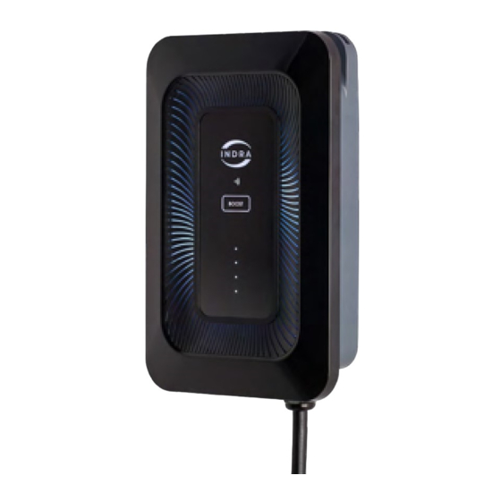
Turbine Lights - Smart LUX™ The Indra Smart LUX™ is fitted with a unique set of turbine lights that correspond with the relevant colour, dependent on the user interaction. These lights trace around the full circumference of the front panel and are visible through the ‘grill’ of the charger. The Turbine lights can be turned off via the Indra App at any time via the settings. Indra Smart Range Installation Guide... - Page 37 What do the LEDs on my charger mean? There are two separate LED indicators on the charger. The Primary LED indicates the charger status, while the four panel LEDs highlight the charger’s current mode. Each of these will illuminate a different colour and will emit a sequence of flashes that indicates the charger’s current state. LEDs relating to the primary LED light: ALL LEDs are off The charger is not receiving power; it may be disconnected from the mains. There is no power to the front panel (The ribbon cable or its connections maybe damaged or disconnected). Primary LED lit, white A solid white LED indicates that the charger is set up and ready to go.
- Page 38 Ensure the Wi-Fi Dongle is successfully paired (Where applicable) • Restart the customer’s router (Where applicable) • Refer to 4G indicator lights (Where applicable) • If it persists, contact Indra customer support Primary LED lit, orange Wi-Fi pairing has been initiated. Indra Smart Range Installation Guide...
- Page 39 LEDs relating to the four ascending panel LEDs 4 panel LEDs are off The charger is not connected to the car. 4 panel LEDs are steady The charger is offering a charge to the car but is “idle” (The car is not accepting a charge). 4 panel LEDs are racing downwards The charger is charging the car (The speed the lights move at represents the rate of charge).
- Page 40 Contact us For more information, please contact us; Online support Email us Call us: www.indra.co.uk/ support@indra.co.uk (+44) 01684 770 631 support...
Need help?
Do you have a question about the Smart Series and is the answer not in the manual?
Questions and answers