
Subscribe to Our Youtube Channel
Related Manuals for LAWO crystal


Summary of Contents for LAWO crystal
- Page 1 User Manual Version: 6.6.0/2 Edition: Tuesday, March 9, 2021 To obtain the latest documentation and software downloads, please visit: www.lawo.com/lawo-downloads...
- Page 2 All rights reserved. Permission to reprint or electronically reproduce any document or graphic in whole or in part for any reason is expressly prohibited, unless prior written consent is obtained from the Lawo All trademarks and registered trademarks belong to their respective owners. It cannot be guaranteed that all product names, products, trademarks, requisitions, regulations, guidelines, specifications and norms are free from trade mark rights of third parties.
-
Page 3: Table Of Contents
4. The Standard Configuration ........................ 15 5. Installation ............................22 6. System Setup ............................ 40 7. Operation ............................57 8. Configuring crystal ........................... 126 9. Audio IO ............................138 10. Audio Mix Engine ..........................161 11. Audio Utilities ........................... 222 12. -
Page 4: Introduction
1. Introduction Introduction Welcome to crystal. About this Manual This document describes all aspects of the system, including the installation, configuration, operation and maintenance. Look out for the following which indicate: Notes - points of clarification. Tips - useful tips and short cuts. -
Page 5: Important Safety Instructions
2. Important Safety Instructions Important Safety Instructions Please observe all of the instructions provided in the "General Safety Information for Lawo Equipment" booklet delivered with your devices. Double-click here to open the information as a pdf. crystal User Manual Version: 6.6.0/2... -
Page 6: The Hardware
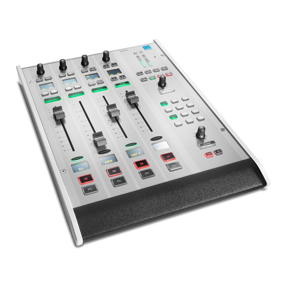
3. The Hardware The Hardware This chapter describes the hardware components and options. Topics include: · System Components · Controls Overview · Control Surface Variants · The Compact Engine · Key Panels 6/459 Version: 6.6.0/2 crystal User Manual... - Page 7 3. The Hardware System Components A complete system consists of up to four components: · crystal Control Surface (essential) – available in five main frame layouts. · Compact Engine (essential) – all audio interfacing, routing, control and signal processing. ·...
- Page 8 The upper section includes a rotary control and four small MF Keys (1, 1a, 2, 2b). Their functions are labeled by the OLED displays. Below the label display are two large MF Keys (3, 4) with foil-printed labels. All MF Keys are defined by the configuration. 8/459 Version: 6.6.0/2 crystal User Manual...
- Page 9 Central Module (951/41-20) Central Modules (left & right) The 4-fader crystal has one Central Module, while all other frame sizes include two (as shown above). The two stereo peak and correlation meters (A and B) are defined by the configuration.
- Page 10 4-fader single frame 12-fader single frame crystal can exist as a single or split-frame control surface. A choice of five main frame layouts are available, with the option to add an extender module to increase the fader count or create a split-frame surface.
- Page 11 4-fader extender 3.3.2 Placement Options crystal is designed to be mounted on a table top surface. All connectors are positioned along the top edge, so you must make sure that these are accessible: 8-fader Surface (top edge) crystal User Manual Version: 6.6.0/2...
- Page 12 Cards can be fitted to either slot position, but to use all 64 channels of a RAVENNA IO card it must use the left slot (7) to support the internal MADI bridge. IO cards must NOT be exchanged while the frame is powered, as to do so may damage the card and/or Compact Engine. 12/459 Version: 6.6.0/2 crystal User Manual...
- Page 13 This is optional and must be ordered separately. If both inputs are connected, then the two feeds provide main and redundant power. The Compact Engine MUST be connected to the mains using the power cable supplied with the system. crystal User Manual Version: 6.6.0/2 13/459...
- Page 14 3. The Hardware Key Panels Key Panel Control. 14/459 Version: 6.6.0/2 crystal User Manual...
-
Page 15: The Standard Configuration
4. The Standard Configuration The Standard Configuration This chapter describes the standard configuration. Topics include: · Introduction · Available Sources · Available Buses · Default Audio Assignments · GPIO Functions crystal User Manual Version: 6.6.0/2 15/459... - Page 16 The standard configuration files are available from the Downloads area at www.lawo.com (after Login). Please note that there is a separate ON-AIR Designer file for each frame size. The "vistool_crystal" project can be used with any of the ON-AIR Designer files. 16/459 Version: 6.6.0/2 crystal User Manual...
- Page 17 Internal Test Tone û û û û DUMMYm mono û û û û DUMMYs stereo The DUMMY sources are included as a starting point (in the configuration) for additional sources to the system. crystal User Manual Version: 6.6.0/2 17/459...
- Page 18 Audio. (DJ) CB T1 mono post-fader N-1 (mix minus) for TEL 1 " CB T2 mono post-fader N-1 (mix minus) for TEL 2 " CB LN mono post-fader N-1 (mix minus) for LINE " 18/459 Version: 6.6.0/2 crystal User Manual...
- Page 19 TEL 1 n-1 mono TEL 2 n-1 left/right ISDN (LINE) n-1 HEADPHONE SOCKETS (Compact Engine rear panel) Output Number Format Default Audio from HEADPHONE 1 left/right MON DJ HEADPHONE 2 left/right MON GUEST crystal User Manual Version: 6.6.0/2 19/459...
- Page 20 EXT 1 left/right EXT 2 left/right PLAYER 1 left/right PLAYER 2 left/right 4.4.4 Digital Outputs AES3 OUTPUT (Compact Engine rear panel) Output Number Format Default Audio from left/right left/right left/right left/right FOLLOW MON CR 20/459 Version: 6.6.0/2 crystal User Manual...
- Page 21 · Incoming call signaling for hybrid sources. Typical GPO applications include: · External redlight switching. · Fader start triggering. · Emergency PGM mute. · Studio loudspeaker mute. · MIC "On" tally for the DJ. crystal User Manual Version: 6.6.0/2 21/459...
-
Page 22: Installation
5. Installation Installation This chapter describes how to install the control surface and Compact Engine. Topics include: · Installing the Control Surface · Installing the Compact Engine · Grounding & Power · Wiring · Synchronization 22/459 Version: 6.6.0/2 crystal User Manual... - Page 23 Please check the contents of the shipping boxes, and in the event of any transport damage, contact your local Lawo representative or email support@lawo.com. A list of serial numbers for all components is included with the shipment. Please keep this list for your records.
- Page 24 Insert the foil plate between the button body and the transparent button cap. Fasten the button cap back onto the button body by pressing it! The photos below are taken from a ruby surface, but the procedure is identical for crystal and sapphire. Remove Button Cap...
- Page 25 Optional The following accessories can be ordered separately: · 1 x external 12V DC power supply (955/50-80) - to connect 12V DC power to the frame. · Expansion IO cards - as described earlier. crystal User Manual Version: 6.6.0/2 25/459...
- Page 26 Please check the contents of the shipping boxes, and in the event of any transport damage, contact your local Lawo representative or email support@lawo.com. A list of serial numbers for all components is included with the shipment. Please keep this list for your records.
- Page 27 Then switch on the unit and check the boot-up sequence on the front panel display. The installation is now complete. Before you can use the IO on a new card, you will need to add the card to the ON-AIR Designer configuration. Audio IO for details. crystal User Manual Version: 6.6.0/2 27/459...
- Page 28 Lift the top cover to remove it and keep the screws and cover in a safe place. You now have access to the Processor Unit and MADI daughter board (on the left), and the two IO card expansion slots (on the right). Top cover screw positions View with cover removed 28/459 Version: 6.6.0/2 crystal User Manual...
- Page 29 Carefully feed the MADI connectors through the holes in the front panel, and position the board onto the white connector of the Processor Unit. Take care to place the connectors so that they match in both directions. crystal User Manual Version: 6.6.0/2 29/459...
- Page 30 Then switch on the unit and check the boot-up sequence on the front panel display. The installation is now complete. Before you can use the new MADI ports, you will need to add the card to the ON-AIR Designer configuration. Audio IO for details. 30/459 Version: 6.6.0/2 crystal User Manual...
- Page 31 DO NOT bend the cards. Start by disconnecting the power and removing the cover plate for the left expansion slot as described earlier. Spare cover plates should be stored safely so that they can be reused later. crystal User Manual Version: 6.6.0/2 31/459...
- Page 32 Then switch on the unit and check the boot-up sequence on the front panel display. The installation is now complete. Before you can use the new streaming channels, you will need to add the card to the ON-AIR Designer configuration. See Audio IO for details. 32/459 Version: 6.6.0/2 crystal User Manual...
- Page 33 5. Installation Grounding & Power 8-fader crystal surface (top edge) Compact Engine (rear view) 5.3.1 Grounding Although operator protection is guaranteed, it is best to establish an additional ground for EMC reasons. On the Compact Engine, a grounding screw is provided beside the DC IN connector on the rear of the frame.
- Page 34 Connect the 12V DC power supply to the DC IN connector on the rear panel. Using the IEC cable provided, connect your AC mains to the PSU. The Compact Engine MUST be connected to the mains using the power cable supplied with the system. 34/459 Version: 6.6.0/2 crystal User Manual...
- Page 35 The ETHERNET port provides a network connection to the Compact Engine control system. This is used to remotely control crystal from VisTool or Ember+ devices; to update the system firmware and configuration; and to network crystal to other Lawo systems.
- Page 36 64 mono channels in the connecting device. For example, the stereo source "MADI 2" will use the audio arriving on channels 3&4; the stereo output named "MADI 3" will send audio out on channels 5&6; and so on. 36/459 Version: 6.6.0/2 crystal User Manual...
- Page 37 20dB PAD. The pre-amp gain can be automatically adjusted using the AutoGain feature. The maximum analog input level (with the PAD enabled) is +24dBu. All AES INPUTs and OUTPUTs conform to the stereo AES3 standard. The four AES INs have sample rate conversion (SRC). crystal User Manual Version: 6.6.0/2 37/459...
- Page 38 In both cases, connections are made using standard 75 ohm BNC connectors. The maximum cable length depends on the equipment you are connecting to. See Synchronization for more details. Grounding & Power Grounding & Power. 38/459 Version: 6.6.0/2 crystal User Manual...
- Page 39 Engine · MADI - connected to the active MADI port. On crystal, this depends on the type of MADI board: o 4-port board - either port 1 (or port 2). o 2-port board - either port 3 (or port 4).
-
Page 40: System Setup
Setting Up the Configuration PC · Updating the Firmware · Uploading a Configuration · Editing the System IP Settings · Setting the System Date and Time · Setting the Time Zone · Can Bus Settings 40/459 Version: 6.6.0/2 crystal User Manual... - Page 41 AC mains to the DC power supply. Using the IEC cable provided, connect the mains supply to the 100-240V AC input on the Compact Engine. The AC mains connections MUST be made using the power cables supplied with the system. crystal User Manual Version: 6.6.0/2 41/459...
- Page 42 Remember to connect power to both the main surface and extender module (using the PSU's provided). The CAN bus must be terminated and so it is important to connect the full chain. Please do not attempt to operate the system with only an extender module connected! 42/459 Version: 6.6.0/2 crystal User Manual...
- Page 43 The hardware components are now ready to be configured - this takes approximately 20 seconds from power Please note: if you perform a cold start, then the system ignores the warm start data and resets to the default values stored in the configuration. crystal User Manual Version: 6.6.0/2 43/459...
- Page 44 ON-AIR Designer installer Web UI Status Monitoring Opened via Web Browser Optionally, you can use VisTool MK2 to remotely control crystal. This is described in the "VisTool MK2 User Guide". 6.3.1 PC Requirements To install and run the ON-AIR Designer, your PC must meet the following requirements: ·...
- Page 45 It is recommended to leave the default "Run" options selected and click on Finish. You can now use SoP Explorer to check the firmware revisions of the system, and ON-AIR Designer to transfer a configuration. If you have any problems with the software installation, please contact your local Lawo representative or email support@lawo.com.
- Page 46 Repeat to interrogate each component as applicable: System, IOs and Surface. If all modules on all components are up to date, then you can close SoP Explorer. Alternatively, use the 'Software Update Wizard' to update the components. 46/459 Version: 6.6.0/2 crystal User Manual...
- Page 47 Once all software modules on all components are equalized, the firmware updates are complete and you can close SoP Explorer. In the unlikely event that the 'Update Wizard' fails, try one of the alternative methods described later. crystal User Manual Version: 6.6.0/2 47/459...
- Page 48 IP address = 192.168.110.253. If the streaming port lies within a different subnet, then you may need to adjust the network settings of the PC's LAN port. Having made a valid network connection, repeat the firmware update procedure to check and update the RAVENNA IO card. 48/459 Version: 6.6.0/2 crystal User Manual...
- Page 49 Switching the Mode of the Compact Engine For crystal and sapphire compact systems, you can use SoP Explorer to switch the mode of the Compact Engine. This operation will perform a factory reset and then restart the Compact Engine with the correct firmware version.
- Page 50 Console 951/21 crystal 952/60 sapphire compact Once the update is complete, the system restarts - select the System component to check the new Hardware revisions: Use the ON-AIR Designer to transfer your system configuration. 50/459 Version: 6.6.0/2 crystal User Manual...
- Page 51 Once boot up is complete, the new configuration data is loaded and the transfer is complete. If your computer’s firewall prevents the transfer, then change your firewall settings and retry. crystal User Manual Version: 6.6.0/2 51/459...
- Page 52 Compact Engine's ETHERNET port. This can be achieved by opening a telnet session as follows. Open a Telnet session to the crystal system. Once login is complete, type in "chparm -ipaddr" (press ENTER) to start the set IP address script. When prompted, enter the new IP address for the system and press ENTER.
- Page 53 Right-click on the unit and select Set System Time. Then confirm by selecting OK. The software now sets the system date and time to match that of the control PC. The success (or failure) of the reset is shown in the SoP Explorer status area: crystal User Manual Version: 6.6.0/2 53/459...
- Page 54 The time zone can be edited by opening a telnet session to the Compact Engine. Open a Telnet session to the crystal system. Once login is complete, type "chparm -tz" (press ENTER). Select option 1 (press ENTER). When prompted, enter the new time zone rule and press ENTER.
- Page 55 The CAN bus speed defines the maximum distance which you can run the cables. A CAN speed of 500 kbit/sec is recommended. Transfer Speed Maximum Distance 500 kbit/sec (recommended) 60 m 100 kbit/sec 300 m crystal User Manual Version: 6.6.0/2 55/459...
- Page 56 CAN Bus Addressing The CAN bus address, also known as the Frame ID, is a unique address which defines the role of each control surface module within the system. For crystal, the following options are supported: · Address 01 to 06 (hexadecimal) are assigned to Fader Modules.
-
Page 57: Operation
Bus Assign · Input Gain & Pan · DSP Parameters · Metering · Monitoring & Talkback · Master Functions · Editing User Labels · Conference Bussing (N-1/Mix Minus) · Snapshots · User Access Rights crystal User Manual Version: 6.6.0/2 57/459... - Page 58 - this takes approximately 20 seconds from power on. To start VisTool, turn on your control PC and double-click on the "VisTool (crystal)" desktop icon. The session loads and then connects to the hardware. On startup, the DOCK appears on the right of the screen.
- Page 59 In a custom configuration, there may be more pages available from the DOCK. For example, to provide metering or advanced options. You can change page using the PAGE UP and PAGE DOWN keys on your PC keyboard. This will scroll through all of the available pages. crystal User Manual Version: 6.6.0/2 59/459...
- Page 60 Note that closing VisTool on the control PC only closes the current session, and is not the same as restarting the system. To do this you will need to restart the Compact Engine (described later). 60/459 Version: 6.6.0/2 crystal User Manual...
- Page 61 (ACCESS keys fully lit green). Fader Use the fader to adjust the source's mix level to the summing bus outputs. The level can be adjusted from - to +9dB. crystal User Manual Version: 6.6.0/2 61/459...
- Page 62 The source label will flash if a fader position needs to be reset. For example, after a snapshot recall. MF Keys 3 & 4 The two large MF keys are programed by the configuration and are defined per source. In the standard configuration, they are channel ON and PFL. 62/459 Version: 6.6.0/2 crystal User Manual...
- Page 63 7. Operation Resetting Fader Positions The crystal faders are not motorised and so the physical faders will NOT be positioned at the correct levels if: · You recall a snapshot which resets fader levels. · You power on (and load the warm start data), having moved the faders.
- Page 64 AGn - enable this key to turn on AutoGain for the DJ and GUEST mics. · On the TONE source, the 4 small keys select the frequency of the tone: 63Hz, 400Hz, 1kHz or 12.5kHz. 64/459 Version: 6.6.0/2 crystal User Manual...
- Page 65 – press BUS and then select a page (1 to 5) to map bus assignments onto the Fader Module. Local Snapshots – press and hold UNLOCK + SNAP RECALL + a memory number (1 to 5) to recall settings from a local snapshot. SNAP STORE works in a similar manner. crystal User Manual Version: 6.6.0/2 65/459...
- Page 66 For the Control Room and Studio outputs, the MUTE and DIM keys allow you to quickly mute or dim the volume of the loudspeakers. All of the monitoring functions are described in more detail later. 66/459 Version: 6.6.0/2 crystal User Manual...
- Page 67 You cannot choose a red source as it is deemed to be on-air. In this instance, first find the source on the surface and close its fader - the button color changes from red to blue, and the source can be selected. crystal User Manual Version: 6.6.0/2...
- Page 68 Is the source already assigned to a different fader strip and the fader open? If so, the source is deemed to be on-air, and so you must find the source and close its fader. 68/459 Version: 6.6.0/2 crystal User Manual...
- Page 69 · MADI = the Group name (defined in the remote matrix). · In 3 = the Signal name (defined in the remote matrix). · Nova17 = the source Display Name (defined in the configuration). crystal User Manual Version: 6.6.0/2 69/459...
- Page 70 When the correct AUX is displayed, turn the control to adjust the level. Aux send levels can be adjusted from -120dB to +9dB. When you have finished editing the bus assignments, deselect BUS (on the Central Module) - the rotary controls and soft keys return to their default functions (described earlier). 70/459 Version: 6.6.0/2 crystal User Manual...
- Page 71 Assigning a Bus to an Output By default, the summing buses are assigned to a number of physical outputs. The assignments can be changed, or reset to the defaults, from the local matrix (in VisTool). crystal User Manual Version: 6.6.0/2 71/459...
- Page 72 If a surround source is assigned to a mono bus, then the stereo downmix is converted to mono by subtracting 3dB from, and then summing, the L and R channels. 72/459 Version: 6.6.0/2 crystal User Manual...
- Page 73 To turn off AutoGain, press the AUTOGAIN button again - the button changes color (blue = off). The mic gain now reverts to its previous value (before AutoGain was enabled), and MIC gain can be adjusted manually. crystal User Manual Version: 6.6.0/2 73/459...
- Page 74 In the standard configuration, each of the MIC sources comes fully-configured with analog and digital input sections; input meter; EQ & Filters; Dynamics (Compressor, Expander and Gate); De-Esser & AutoMix; and a Limiter. Other sources support a subset of these parameters. 74/459 Version: 6.6.0/2 crystal User Manual...
- Page 75 The surface controls are paged through different parameter sets using the INP, DYN, LIM, DLY and EQ keys on the Central Module. Note that the rotary controls and soft keys across all 4 fader strips are utlised when working in this mode. crystal User Manual Version: 6.6.0/2 75/459...
- Page 76 When you have finished adjusting the parameters, deselect the ACCESS key - the fader strip soft keys and rotary controls return to their default functions (described earlier), and the VisTool "Source Parameters" page closes. The next few topics describe the source parameters in more detail. 76/459 Version: 6.6.0/2 crystal User Manual...
- Page 77 PAN - left/right panning onto the stereo buses. (This parameter is not shown on VisTool). MIC gain, channel GAIN and PAN can also be adjusted from the fader strip rotary control (as described earlier). crystal User Manual Version: 6.6.0/2 77/459...
- Page 78 (Middle) and the other (bi- directional) at right angles to provide the stereo ambience (Side). The crystal system provides M-S to X-Y decoding to turn a Middle and Side signal into normal Left and Right stereo.
- Page 79 Dynamics section: Compressor, Expander and Gate. This changes dynamically as the signal level varies, and so is extremely helpful when adjusting parameters. If a red ball is also visible, then this represents the output level of the De-Esser. crystal User Manual Version: 6.6.0/2 79/459...
- Page 80 The characteristic of the compressor is optimized for radio on-air operation. The ratio pivot point moves around the working point according to the input signal level and not around a fixed threshold. This allows the ratio to adapt without having to change the level considerably. 80/459 Version: 6.6.0/2 crystal User Manual...
- Page 81 Both DYN and EXP must be enabled (red) for the expander to be active. This is best checked by looking at VisTool (where you can see the DYN button plus on/off for the individual sections: COMP, EXP, GATE, etc.) crystal User Manual Version: 6.6.0/2 81/459...
- Page 82 Both DYN and GATE must be enabled (red) for the expander to be active. This is best checked by looking at VisTool (where you can see the DYN button plus on/off for the individual sections: COMP, EXP, GATE, etc.) 82/459 Version: 6.6.0/2 crystal User Manual...
- Page 83 Both DYN and DeEss must be enabled (red) for the de-esser to be active. This is best checked by looking at VisTool (where you can see the DYN button plus on/off for the individual sections: COMP, EXP, GATE, etc.) crystal User Manual Version: 6.6.0/2 83/459...
- Page 84 Both DYN and AMix must be enabled (red) for AutoMix to be active. If the master DYN button is not enabled, then the AMix button is dim to indicate that AutoMix is not yet active. 84/459 Version: 6.6.0/2 crystal User Manual...
- Page 85 RLS - release time from 10ms to 5000ms. The Limiter graph on VisTool includes a green ball which represents the output level of the Limiter. This changes dynamically as the signal level varies, and so is extremely helpful when adjusting parameters. crystal User Manual Version: 6.6.0/2 85/459...
- Page 86 Time - the delay time is displayed and adjusted in either ms, meters (m) or frames (frms). You can turn any of the three rotary controls to set the delay time. @48kHz, PAL Delay (ms) 0 to 340 Delay (meters) 0 to 112 Delay (frames) 0 to 8 86/459 Version: 6.6.0/2 crystal User Manual...
- Page 87 Press down on the left (master) rotary control to access the second page (for the 2-band Filters). Ø Press again to return to the 3-band parametric EQ (page 1). The EQ graph on VisTool shows all five bands of EQ simultaneously. This provides a great overview of the complete section. crystal User Manual Version: 6.6.0/2 87/459...
- Page 88 For the GAIN/FREQ control, turn to adjust the Gain, and then press down and turn to adjust Frequency. The EQ button acts as the master on/off for the complete section: 3-band parametric EQ + 2-band filters. 88/459 Version: 6.6.0/2 crystal User Manual...
- Page 89 For the GAIN/FREQ control, turn to adjust the Gain, and then press down and turn to adjust Frequency. The EQ button acts as the master on/off for the complete section: 3-band parametric EQ + 2-band filters. crystal User Manual Version: 6.6.0/2...
- Page 90 On the control surface, each meter is accompanied by a stereo correlation meter. On VisTool, you also have loudness metering for PGM 1. On a 4-fader console, there is no second Central Module and so the PGM 1 meter appears on VisTool only. 90/459 Version: 6.6.0/2 crystal User Manual...
- Page 91 The integrated loudness measurement is controlled by the on-screen Start, Stop and Reset buttons. It is very useful for measuring loudness over a longer period - for example, for the duration of the show. The measurement is displayed in LUFS (Loudness Units Full Scale). crystal User Manual Version: 6.6.0/2 91/459...
- Page 92 Default Audio Assignments The default audio assignments are as follows. Monitor Section Connector Location Outputs MON CR LINE OUTPUT (rear panel) 3&4 MON DJ HEADPHONE 1 (rear panel) MON GUEST HEADPHONE 2 (rear panel) 92/459 Version: 6.6.0/2 crystal User Manual...
- Page 93 MUTE and DIM keys allow you to quickly mute or dim the volume of the loudspeakers. The stereo PPM on the first Central Module follows the MON CR source selector. The meter shows the level before the Volume, Mute and Dim. crystal User Manual Version: 6.6.0/2 93/459...
- Page 94 The extension will replace the PGM 1 metering and loudness controls, and be clearly labeled (e.g. CR for control room): DOCK (default) DOCK (with MON CR Extension) To close an extension, turn off its activation button - the DOCK returns to its default state (with PGM 1 metering). 94/459 Version: 6.6.0/2 crystal User Manual...
- Page 95 When SPLIT is active (red), the DJ will hear different signals in the left and right ears of their headphones: left ear = PFL (or CUE); right ear = the current monitor source (e.g. PGM 1). You can use this mode to monitor the main program output while cueing up another source (pre-fader). crystal User Manual Version: 6.6.0/2 95/459...
- Page 96 Whenever PFL (or CUE) is active, the bus is switched to the control room speakers and DJ headphones. The monitor outputs will return to their active monitor source once all PFL (or CUE) selections are cleared. Select CLEAR PFL on the Central Module to cancel all active PFLs quickly. 96/459 Version: 6.6.0/2 crystal User Manual...
- Page 97 11 hours, 49 minutes and 03 seconds. For greater visibility, the "seconds" are also represented by the blue line/circle around the circumference of the display. crystal User Manual Version: 6.6.0/2...
- Page 98 To set the Preset and Alarm time values, select the current count-down time - the Timer properties window opens: The Preset value defines the starting time. When you reset the timer, it will return to this setting - in our example, to 50 seconds. 98/459 Version: 6.6.0/2 crystal User Manual...
- Page 99 The MIC OPEN / REDLIGHT indicator lights in red whenever at least one MIC source fader is on-air (channel ON and fader open). If no MIC faders are on-air, then the indicator goes out. The state is triggered by the four MIC sources. crystal User Manual Version: 6.6.0/2 99/459...
- Page 100 Thus, if a source is deleted from the configuration, the labels of all sources with a larger sys number are moved (shifted downwards). The sys numbers can be viewed in the Ember+ tree to see what affect this may have on your system. 100/459 Version: 6.6.0/2 crystal User Manual...
- Page 101 PC Labels function. It is important that the Station ID (defined for the "Logic -> VispageSwitch" element) matches the one entered in VisTool Sessions. If not, the trigger from the remote system will not work. crystal User Manual Version: 6.6.0/2 101/459...
- Page 102 Close all three source faders. The CONF buttons become red and all sources will hear the conference bus minus themselves. In other words, they can hear each other, but not themselves, and chat off-air. 102/459 Version: 6.6.0/2 crystal User Manual...
- Page 103 PGM 1 mix minus. This state is reflected by the white CONF button. To cancel the conference for any of the sources, deselect the CONF button. The CONF buttons turn green (off) and the source’s monitor feed receives PGM 1 minus themselves at all times. crystal User Manual Version: 6.6.0/2 103/459...
- Page 104 Load Audio Always - if ticked, audio-related parameters are loaded for all faders regardless of the Load max. Fader No. You can use this option to load audio-related parameters to all faders, while loading fader strip assignments up to a certain fader number. 104/459 Version: 6.6.0/2 crystal User Manual...
- Page 105 You can see which memories contain data by looking at the lit buttons - in our example, there is data stored in memories 1, 2, 4 and 5. Keep holding SNAP RECALL and select a memory - e.g. number 4. The SNAP RECALL button flashes magenta to indicate a successful operation and the console resets. crystal User Manual Version: 6.6.0/2 105/459...
- Page 106 Keep holding SNAP RECALL and SNAP STORE and select a memory - e.g. number 4. The snapshot memory if cleared. To check if the operation has been succesful, press and hold SNAP RECALL - the memory number should now be clear (unlit). 106/459 Version: 6.6.0/2 crystal User Manual...
- Page 107 The setup for this is described in the VisTool MK2 User Guide. VisTool snapshots store the same settings as the five internal memories on Lawo's radio on-air consoles. When you save, you can choose to save either a Full snapshot (to save settings globally across the console), or Source snapshot (to save only the settings for the source in access).
- Page 108 Note that the snapshot Group and Type cannot be changed. You can enter text to describe the snapshot into the Comment field if you wish. If your system supports a user login, then different snapshot groups may be available (via the more.. button). See User Access Rights for more details. 108/459 Version: 6.6.0/2 crystal User Manual...
- Page 109 Note that the snapshot Group and Type cannot be changed. You can enter text to describe the snapshot into the Comment field if you wish. If your system supports a user login, then different snapshot groups may be available (via the more.. button). See User Access Rights for more details. crystal User Manual Version: 6.6.0/2 109/459...
- Page 110 Note that Source snapshots can be loaded either to the source in access OR to their original source (if nothing is in access). The original source is identified in the Source column. Select a snapshot from the list (e.g. crystal default) and select OK - the window closes and the settings are loaded to the system.
- Page 111 (via the more.. button). User Access Rights for more details. Select a snapshot from the list and select OK - the window closes and the snapshot is deleted. crystal User Manual Version: 6.6.0/2 111/459...
- Page 112 Once the configuration is uploaded to the system, users can login via the LOGIN button. An administrator will need to prepare the system for other users via the Admin pages. Non-admin users can then login to access their permitted snapshot groups and operations. 112/459 Version: 6.6.0/2 crystal User Manual...
- Page 113 "Nobody" user logs in. This allows the console to be reset to a default state and/or its operations restricted, by defining a login snapshot and restricted rights access for the user "Nobody". This is handled from the Admin pages in the usual manner. crystal User Manual Version: 6.6.0/2 113/459...
- Page 114 Select Change Password. Enter your new password into both the Password and Repeat fields, and select OK. There are no restrictions on the characters used for a password. Test the new password by logging out logging 114/459 Version: 6.6.0/2 crystal User Manual...
- Page 115 In addition, you will need to create a single snapshot group named User Snapshots which is assigned to both user groups: Users and Administrators. The correct setup is shown below in the "Edit User" and "Edit Group" pages: Edit User Edit Group crystal User Manual Version: 6.6.0/2 115/459...
- Page 116 The Snap Group named "User Snapshots" should be assigned to the group, and only the Load SrcSnap and Load boxes should be ticked. Leave all other options unticked, so that any standard users will have load access only. 116/459 Version: 6.6.0/2 crystal User Manual...
- Page 117 The setup is now complete. Log in as the "Admin" user to save snapshots into the "User Snapshots" snap group. Then logout to activate the "Nobody" user. The rest of this topic describes each of the Admin pages in more detail. crystal User Manual Version: 6.6.0/2 117/459...
- Page 118 For users to access the new snapshot group, you must add it to a user group. All members of the user group will then be able to access the snapshot group, according to the snapshot group access options. 118/459 Version: 6.6.0/2 crystal User Manual...
- Page 119 Snap Groups - this area defines the snapshot groups which users can access (see next page). On the left are all snapshot groups defined in the VisTool snaphots database. On the right are the snapshot groups which are available to the user group. crystal User Manual Version: 6.6.0/2 119/459...
- Page 120 The Snap Groups list shows all snapshot groups defined in the VisTool snaphots database. If you have not yet created any snapshot groups, then this list will be empty. Go to Edit Snap Group to create some snapshot groups. 120/459 Version: 6.6.0/2 crystal User Manual...
- Page 121 Rights are copied into the new user group name. · Delete - select a user group and Delete to delete an existing user group. The Delete user group operation cannot be undone, so take care when using this function. crystal User Manual Version: 6.6.0/2 121/459...
- Page 122 Reset - resets the user's password to 0000. (Very useful if a user forgets their password). · Comment - you can enter comments if you wish. · User Groups and Member of - defines which user groups the user belongs to (see next page). 122/459 Version: 6.6.0/2 crystal User Manual...
- Page 123 Use the Up and Down buttons to change the order in the Snapshot Order list (on the right). Snapshots load from top to bottom after the user successfully logs in. crystal User Manual Version: 6.6.0/2 123/459...
- Page 124 When you have finished editing both the General and Snapshots properties, select OK. The 'Edit User' window updates to show the new user - Sue - and their user groups - DJs: Continue selecting OK to confirm and close all the Admin windows. 124/459 Version: 6.6.0/2 crystal User Manual...
- Page 125 VisTool snapshots between computers. Select a different snapshot group using the more.. button. When you have finished editing both the Snapshot properties, select OK to save any changes and return to the Admin page options. crystal User Manual Version: 6.6.0/2 125/459...
-
Page 126: Configuring Crystal
8. Configuring crystal Configuring crystal This chapter describes how to configure crystal. You should be familiar with the ON-AIR Designer configuration tool. If not, please refer to the separate "ON-AIR Designer User Guide". Topics include: · Starting a Configuration ·... - Page 127 8. Configuring crystal Starting a Configuration The simplest way to customize a system is to modify the existing or standard configuration. To do this, you will need a copy of the latest .db3 project file. You can then use the ON-AIR Designer software to open, edit and save the file;...
- Page 128 - Frame selection The four 'Frame' areas define the System Core, Surface, Panels and Screen functions. · System Core = the DSP Core. For crystal there is only one option: the Compact Engine. · Surface = the maximum control surface size.
- Page 129 8. Configuring crystal Once you have selected a template or specified the 'Frame' , click on Finish. The software creates the new project. Depending on the product and its specification, a number of windows will open. In our example, we can see the 'Project' window (on the left), plus the 'System Core' (in the central working...
- Page 130 8. Configuring crystal Opening an Existing Configuration To open an existing project stored on your computer: Select File -> Open from the top menu bar, or click on the Toolbar icon, or use the keyboard shortcut (CTRL + O). Select your project file and click on Open.
- Page 131 8. Configuring crystal Checking the Network Communication You can check the network connection to the Lawo system by opening a project and ticking the Online checkbox. The two indicators show the connection status: green = valid connection; red = not connected; yellow = the device firmware needs updating.
- Page 132 8. Configuring crystal Changing the Frame The 'Change Frame' window can be used to change the maximum specification of the system. Select Frame -> change frame to open the window. Here you can change the specification of any component: System Core, Surface, Panels or Screen.
- Page 133 8. Configuring crystal Monitoring the Resources The 'Resources' window can be used to check the DSP resources used by the project. Select Command -> Resources to open the window. The counters show how many resources are left out of the maximum available. The maximum numbers vary depending on the product.
- Page 134 8. Configuring crystal Saving the Project At regular intervals you should save the project, and also use "save as" to keep a copy of the project at different revision stages. This will allow you to test the configuration and revert to an earlier version if necessary. The screenshots below are taken from Power Core, but the procedure is identical for all on-air systems.
- Page 135 This function transfers the setup parameters defined in the 'Project' window to the selected unit. The screenshot below is taken from crystal, but the procedure is identical for all radio on-air systems. Start by opening the project you wish to transfer.
- Page 136 8. Configuring crystal 8.8.1 Editing the System IP Address If the System Core is a Compact Engine, Nova29 or Nova17, you can use the ON-AIR Designer setup data to change the system IP address. (Note that, for Power Core, the system IP address must be edited using either the front panel controls or Web UI).
- Page 137 8. Configuring crystal Transferring Configuration Data to the Unit This function transfers the configuration parameters to the selected unit. The screenshot below is taken from Power Core, but the procedure is identical for all radio on-air systems. Start by opening the project you wish to transfer.
-
Page 138: Audio Io
9. Audio IO Audio IO This chapter describes how to configure the audio IO. Topics include: · Setting Up IO Cards · Setting Up MADI · Setting Up RAVENNA/AES67 · Setting Up Synchronisation 138/459 Version: 6.6.0/2 crystal User Manual... - Page 139 The IO parameters are organized per card/connector. The topics which follow describe the parameters for each type of signal. Parameters can also be edited in list form using 'Command -> Inputs' or 'Command -> Outputs'. crystal User Manual Version: 6.6.0/2...
- Page 140 MtxCon (NovaConnect) software. · LS - sets the input for control from the optional Line Scheduler (LS) product. Please contact your local Lawo representative for details. · OFF – the input is not enabled for external matrix control.
- Page 141 Default Audio assignments if they are overridden during operation of the system. A Default Audio source cannot be assigned if Matrix Enable is active. crystal User Manual Version: 6.6.0/2 141/459...
- Page 142 This option enables matrix control of the output (as described earlier). If the option is enabled, you cannot use the Default Audio function. Default Audio Double-click in the Default Audio box to assign a default audio source for the output (as described earlier). 142/459 Version: 6.6.0/2 crystal User Manual...
- Page 143 This option enables matrix control of the input (as described earlier). Transparent Select this checkbox to set the input to be “transparent”. The option should be enabled if you are using the input to route a Dolby E signal. crystal User Manual Version: 6.6.0/2 143/459...
- Page 144 Select this checkbox to set the output to be “transparent”. The option should be enabled if you are using the output to route a Dolby E signal. Default Audio Double-click in the Default Audio box to assign a default audio source for the output (as described earlier). 144/459 Version: 6.6.0/2 crystal User Manual...
- Page 145 To configure redundant MADI outputs, check the P2 Tx=P1 Tx option. Now MADI port P2 transmits the same data as port P1. You can use this procedure to configure each odd/even pair of MADI ports. crystal User Manual Version: 6.6.0/2 145/459...
- Page 146 RAVENNA input and output. Once the configuration is in place, the RAVENNA Web UI must be used to map the RAVENNA signals to the Tx and Rx streams. 146/459 Version: 6.6.0/2 crystal User Manual...
- Page 147 Then open the "Audio Input" branch of the 'Tree Definition', select the Compact Engine Madi card and the RAVENNA tab: The Enable MADI over RAVENNA options should be set to On for MADI 1 and Off for all other ports. crystal User Manual Version: 6.6.0/2 147/459...
- Page 148 Default RAVENNA Source Label (optional) - defines the stream you wish subscribe to by entering its RAVENNA Source Label. This option can be used to permanently link the receiver to a stream. To use this feature, you must follow the [GroupName]:[SignalName] labeling convention described above. 148/459 Version: 6.6.0/2 crystal User Manual...
- Page 149 Alternatively, open a web browser application and enter the IP address of the connected streaming port into the URL field. The default IP addresses are: · ETHERNET A = 192.168.101.250 · ETHERNET B = 192.168.110.253 crystal User Manual Version: 6.6.0/2 149/459...
- Page 150 Landing Page - opening the RAVENNA Web UI RAVENNA Web UI (Home page) Note that the Landing Page preview uses a static library image and does not update in real time or represent the actual settings on the connected device! 150/459 Version: 6.6.0/2 crystal User Manual...
- Page 151 ETHERNET B = 192.168.110.253 Default subnet mask = 255.255.255.0 Note that, in the RAVENNA Web UI, the two ports are labeled as follows: · ETHERNET A = streaming port ra0 · ETHERNET B = streaming port ra1 crystal User Manual Version: 6.6.0/2 151/459...
- Page 152 Then select Reboot - the device must be rebooted before the new settings take affect, which means that you will lose your browser connection. Once the reboot is complete, re-open the RAVENNA Web UI to check the changes. 152/459 Version: 6.6.0/2 crystal User Manual...
- Page 153 9.3.8 Synchronization (PTP) A crystal standard configuration system will automatically use the highest prioritized sync source (if a valid signal is present): MADI, Wordclock, AES3 or internal clock. Note that the MADI option actually means PTP, due to the internal workings of the system.
- Page 154 Once you have chosen a stream, click on Apply - the Rx stream name on the Home page updates to show the stream name in (). If the source RAV In 1 is assigned to a fader strip, then it should now be receiving some audio. 154/459 Version: 6.6.0/2 crystal User Manual...
- Page 155 Tx Streams list when you open the RAVENNA Web UI Home page. Unless you wish to create additional Tx streams, there is no need to edit the configuration from the Web UI. RAVENNA Web UI (Default Stream Setup) crystal User Manual Version: 6.6.0/2 155/459...
- Page 156 PTP signal. Hover your mouse over the graph to reveal further information. Ø Click on PTP to view or edit the PTP Properties for the device. 156/459 Version: 6.6.0/2 crystal User Manual...
- Page 157 This area defines the sending streams, which are used to publish audio from the device to the network. The Tx streams are pre-defined by the crystal standard configuration. In each case, you will see the Tx stream name and the RAVENNA media channels which are being used.
- Page 158 You will also see an icon on the right of each Rx stream which reflects the same statuses. Click on the icon to open the Statistics window - this provides more information about the stream. Healthy Rx Stream (green) Unhealthy Rx Stream (orange) 158/459 Version: 6.6.0/2 crystal User Manual...
- Page 159 (DALLIS Master Board). Click on Reset Stats to clear the statistics history for the selected stream. Return to the Home page and click on the Reset button to clear the statistics history for all Rx streams. crystal User Manual Version: 6.6.0/2 159/459...
- Page 160 Selects a logic control signal to switch the system sample rate from 48kHz (default) to 44.1kHz. To switch the sample rate you must check the Enable Samplerate Switch box AND apply a logic control signal. 160/459 Version: 6.6.0/2 crystal User Manual...
-
Page 161: Audio Mix Engine
Topics include: · Sources · Summing buses · Conf Buses · DSP Parameters · PFL Monitoring · Monitoring Master Control & Talkback · Monitoring Signal Selection · Tone Generator · Signal Metering · Surround Mixing crystal User Manual Version: 6.6.0/2 161/459... - Page 162 EQ – 3-band parametric EQ plus High and Low Pass Filters. · Dynamics – Gate, Expander, Compressor and De-Esser/AutoMix sections. · Limiter – independent limiter. · Delay – adjustable in ms, metres or frames. 162/459 Version: 6.6.0/2 crystal User Manual...
- Page 163 A source must be named before it can be referenced to other elements via the 'Tree Selection'. For crystal, sapphire compact and sapphire MK2, the source type is defined when you insert the source element. This topic covers normal audio sources. The other source types are described later.
- Page 164 CD, you will need to enter different Alias names in order to save and load snapshots. If an Alias name is not entered then snapshot data is referenced to the ‘Display’ name. 164/459 Version: 6.6.0/2 crystal User Manual...
- Page 165 When using a Nova17, Nova29 or Matrix Server, enter the Pool ID defined in the corresponding MTx Src Pool element. When using a Nova73, enter the class configured in the Nova73 map (as described in the "ext_router_control_en" pdf). crystal User Manual Version: 6.6.0/2 165/459...
- Page 166 Parm Page User Off This input locks out all DSP modules for the source. You may use this to prevent parameters such as a presenter’s mic EQ and Compression from being altered by the operator. 166/459 Version: 6.6.0/2 crystal User Manual...
- Page 167 Active when the source is phase reversed. Mono (stereo sources only). Active when the source is in mono. The remaining source parameter tabs are described later. See Source -> PFL, Conf, DownSrc, Aux, Keys Fader Status. crystal User Manual Version: 6.6.0/2 167/459...
- Page 168 Select OK to confirm and close the 'Tree Selection' window - the parameter box updates to show your assignment. To remove an entry, click anywhere inside the entry box and press DEL on your PC keyboard. 168/459 Version: 6.6.0/2 crystal User Manual...
- Page 169 Enter six characters or less so that the name can appear in full on the control surface displays. You can use copy (F5) + paste (F6) or incremental paste (F7) to quickly edit a series of source names. crystal User Manual Version: 6.6.0/2...
- Page 170 To assign a de-esser or automixing, enable the DeEsser / AutoMix box. This option is available on mono sources only. The signal processing is described in more detail later, see Parameters. You can keep track of how many resources are available by opening the "Command -> Resources" window. 170/459 Version: 6.6.0/2 crystal User Manual...
- Page 171 Note that in Normal Mode, the Background level is always 0dB and has no action; in Hot Fader Mode, the operator sets the Surface level, while RAS or fader logic signals control the Background level. crystal User Manual Version: 6.6.0/2...
- Page 172 Use this output in Hot Fader mode, or on non-moving fader systems, to flag when the RAS or logic has opened a fader position, but the physical surface fader is closed. Fader Touch active Active if the fader sense is active (the fader is touched). 172/459 Version: 6.6.0/2 crystal User Manual...
- Page 173 The most important fields are the Name and Type (defined in the Parm tab): A sum bus must be named before it can be referenced to other elements via the 'Tree Selection'. For crystal, sapphire compact and sapphire MK2, the type is defined when you insert the summing bus element.
- Page 174 First, assign the sum bus to a loopback output, and then assign the loopback return to a source. The source may then be assigned to the sum bus in the usual manner. Audio loopbacks are described later. 174/459 Version: 6.6.0/2 crystal User Manual...
- Page 175 Use the Limiter, Compressor, Equalizer and/or Delay checkboxes to enable each processing module. The signal processing is described in more detail later, see Parameters. You can keep track of how many resources are available by opening the "Command -> Resources" window. crystal User Manual Version: 6.6.0/2 175/459...
- Page 176 Use this option to prevent operators from adjusting assignments onto a bus (e.g. PGM). Fader Enable Assigns the control trigger which will switch the bus send levels onto the faders (globally across the console). 176/459 Version: 6.6.0/2 crystal User Manual...
- Page 177 This control input will switch the send to Aux n to pre fader. Aux n Post This control input will switch the send to Aux n to post fader. Aux n Off This control input will switch the send to Aux n Off. crystal User Manual Version: 6.6.0/2 177/459...
- Page 178 This control input will assign the source to Aux n. The first press assigns the source pre-fader; the second press is post fader; and the third press is off. Post Only If this box is checked, then there is no pre-fader option. 178/459 Version: 6.6.0/2 crystal User Manual...
- Page 179 - sums the left and right inputs and applies a -3dB gain offset. · side - reverses the left and right inputs. · Gain - digital gain from -30dB to +18dB. · Basis - left/right width. · Bal - left/right input balance. crystal User Manual Version: 6.6.0/2 179/459...
- Page 180 If a surround source is assigned to a mono bus, then the stereo downmix is converted to mono by subtracting 3dB from, and then summing, the L and R channels. 180/459 Version: 6.6.0/2 crystal User Manual...
- Page 181 Enter the AutoGain target level in dBr. The default value is 0. 10.3.3 Dynamics The dynamics DSP module can be configured for sources and summing buses. The module includes an independent compressor, expander and gate. crystal User Manual Version: 6.6.0/2 181/459...
- Page 182 DYN - on/off for all dynamics sections: compressor, expander, gate (and de-esser/automix). · GATE - on/off for the gate. · THRS - threshold from -93dB to +27dB. · ATT - attack time from 0.16ms to 82ms. · RLS - release time from 10ms to 5000ms. 182/459 Version: 6.6.0/2 crystal User Manual...
- Page 183 For sapphire and Power Core, up to 4 independent AutoMix groups may be created. crystal and sapphire compact support a single AutoMix group.
- Page 184 The delay module can be configured for sources and summing buses. The delay time is displayed and adjusted in either ms, meters (m) or frames (frms). @48kHz, PAL Delay (ms) 0 to 5300 Delay (meters) 0 to 1749 Delay (frames) 0 to 132 184/459 Version: 6.6.0/2 crystal User Manual...
- Page 185 Display name for the conference bus used on the control surface. Enter 6 characters or less. Source Color Selects the color used to illuminate the LAWO backlight on the control surface when this source is assigned to a fader strip.
- Page 186 If a source is assigned to a Conf Bus 1, then you can use the control input Conf 1n to assign its own signal to the conference bus. With a rising edge source is added and with a falling edge it is taken away. 186/459 Version: 6.6.0/2 crystal User Manual...
- Page 187 – this allows members of the conference to hear each other while they are off- air. There are two completely separate conference systems (Conf 1 and Conf 2), each of which may be used to generate multiple mix minus or N-n feeds. crystal User Manual Version: 6.6.0/2 187/459...
- Page 188 Most important is the Reference name - in our example, CB_DJ. Tick Conf 2 if the bus is to be part of the second conference system, or leave it blank to use Conf 1. Conf Bus for details on the remaining parameters. 188/459 Version: 6.6.0/2 crystal User Manual...
- Page 189 To create an N-many, assign the same conference bus to multiple sources. To use the second conference system, assign the bus to Conf 2 Bus. (The Conference bus should also have its Conf 2 parameter enabled, see step 1.) crystal User Manual Version: 6.6.0/2 189/459...
- Page 190 Our example uses the Conf 1 off, Conf 1 in use and Conf 1 Audio control signals. This creates an MF Key which will add or remove the source to/from the Conference 1 system, and illuminate in different colors to indicate the conference state. See Source -> Conf for more parameter and status options. 190/459 Version: 6.6.0/2 crystal User Manual...
- Page 191 PFL bus. Multiple AFLs may be summed. AFL is only cancelled by deselecting the AFL button. · AFL/PFL - as for AFL, but the channel's PFL signal is heard when the fader is closed; when the fader opens, the listen bus receives AFL. crystal User Manual Version: 6.6.0/2 191/459...
- Page 192 This is done using Sum Buses in the usual manner. Note that PFL 3, 4 and 5 are not supported by crystal. Start by selecting "System -> Definition" in 'Tree Definition' and the Audio tab. Scroll down to access the "Parameter = PFL Mode"...
- Page 193 PFL assigned Indicates which PFL bus (1 to 5) is assigned as “PFL 1”. PFL 1 may be swapped with another PFL bus (from 1 to 5) from “Surface -> Fader Module -> PFL1 Swap”. crystal User Manual Version: 6.6.0/2 193/459...
- Page 194 Our example uses PFL 1 off, PFL 1 prepare and PFL 1 active. This creates an MF Key which will turn PFL on or off when pressed, and illuminate in different colors to indicate the PFL state. 194/459 Version: 6.6.0/2 crystal User Manual...
- Page 195 Use the ChX.x field to select the PFL bus which will be used by the fader strip. The options are: · Default = PFL 1 (the predefined PFL bus) · PFL 2 to PFL 5 – the user-defined buses configured in “System -> Definition -> Parameter = PFL Mode”. crystal User Manual Version: 6.6.0/2 195/459...
- Page 196 The signal flow is shown below. Note that the left and right channels are treated independently, and the talkback inputs differ (depending on the Minimixer type). 196/459 Version: 6.6.0/2 crystal User Manual...
- Page 197 Creating a Minimixer Each Minimixer should be inserted under the "Minimix" branch of the 'Tree Definition'. 10.6.4 Audio Parameters The audio parameters (in the Global, Dim and Mute tabs) are identical for all Minimixer types. crystal User Manual Version: 6.6.0/2 197/459...
- Page 198 Level is then superimposed. This function permits level balancing. Level Right The Default Level(s) are applied when nothing is assigned to Level Left or Level Right. Balance Pot Assigns a level control to adjust the left/right balance of the Minimixer. 198/459 Version: 6.6.0/2 crystal User Manual...
- Page 199 This is the level applied to the left and right output channels of the minimixer when the Out Dim 1 L or Out Dim 2 L, and Out Dim 1 R or Out Dim 2 R control signals are active. Level is set in crystal User Manual Version: 6.6.0/2...
- Page 200 Assigns input control signals to mute the left and right output channels of the Minimixer (after main level, before TB insertion). Out TB Mute L/R Assigns input control signals to mute the left and right output channels of the Minimixer after TB (talkback) insertion. 200/459 Version: 6.6.0/2 crystal User Manual...
- Page 201 An example is included later. Once named, the control can be used to control the level of another element by clicking on any yellow "Level" parameter field and selecting the control 's Gain Out in the 'Tree Selection': crystal User Manual Version: 6.6.0/2 201/459...
- Page 202 Note also that Balance Controls take their name from the "Level Control" Reference name, and so do not appear separately under the "Balance Control" branch of the 'Tree Definition'. 202/459 Version: 6.6.0/2 crystal User Manual...
- Page 203 Fader Level Out control to the desired parameter field (Level): Once the configuration is saved and transferred, assign the source named HP Level to a fader strip. You can now remotely control the Minimixer level from its fader. crystal User Manual Version: 6.6.0/2 203/459...
- Page 204 Sys TB tab). On crystal, two signals can be assigned: Sys TB 1 and Sys TB 2. On sapphire, sapphire compact and Power Core, up to eight signals can be assigned: Sys TB 1 to 8. Any two can be used in each Minimixer Sys TB.
- Page 205 “System -> Definition -> Audio = Internal”). Sys TB 2 Select These fields are not visible for crystal (as only two talkback sources are supported). Sys TB 1 Assign an input control signal to sum each talkback source with both the left and right channels of the Minimixer.
- Page 206 Assigns an input control signal to switch the connect on. Audio In 1 Selects the left and right input sources. Audio In 2 Audio Out 1 Selects the left and right output destinations. Audio Out 2 206/459 Version: 6.6.0/2 crystal User Manual...
- Page 207 Assigns the audio source for each input. Input 7 takes highest priority. For example, if both input 4 and input 7 triggers are active, then input 7 is the audio source routed to the output of the Priconnect. crystal User Manual Version: 6.6.0/2 207/459...
- Page 208 · Audio In N.1 to Audio Out 1 · Audio In N.2 to Audio Out 2 Audio In N.1 Assigns the left audio input source. Audio In N.2 Assigns the right audio input source. 208/459 Version: 6.6.0/2 crystal User Manual...
- Page 209 The Out State of the master element should be assigned to the In State of the slave. The slave will then follow all switch changes which occur in the master. crystal User Manual Version: 6.6.0/2...
- Page 210 This is an audio signal with all bits set to binary ‘1’. It can be used for measurement purposes. 10.8.1 Assigning the Signals Each signal can be assigned to any audio input via the "Definition -> Audio" branch of the 'Tree Selection' window. Test Tone Source (example) 210/459 Version: 6.6.0/2 crystal User Manual...
- Page 211 Sys TB tab). On crystal, two signals can be assigned: Sys TB 1 and Sys TB 2. On sapphire, sapphire compact and Power Core, up to eight signals can be assigned: Sys TB 1 to 8. Any two can be used in each Minimixer Sys TB.
- Page 212 - 27 - 28 - 38 - 24 Analog Reference Level Operating Level (analog) +6 dBu + 8 dBu + 4 dBu +6 dBu Operating Level (digital) - 9 dBFS -10dBFS -20dBFS - 6 dBFS 212/459 Version: 6.6.0/2 crystal User Manual...
- Page 213 In our example, the signal present indicator will illuminate as follows: · Signals > 6dBR – fully-lit red. · Signals > -1dBR – fully-lit yellow. · Signals > -30dBR – fully-lit green. · Signals < -30dBR – half-lit black (off). crystal User Manual Version: 6.6.0/2 213/459...
- Page 214 The metering elements can be used stand-alone or combined as described in the examples below. Use the PPM element in VisTool Editor to configure the components. Loudness metering is configured separately using the Loudness element. 214/459 Version: 6.6.0/2 crystal User Manual...
- Page 215 DSP module is on. DYN is the status of the master dynamics on/off; COMP, EXP and GATE show the status of the individual sections. · VCA Grouping (not available for crystal) - if the fader is assigned to a VCA, then the VCA master is shown here. ·...
- Page 216 LUFS (Loudness Units Full Scale). Loudness Range Measurement (LRA) A loudness range measurement is similar to the integrated loudness measurement, described above, but is gated (at -70dB LUFS) to exclude silence from the measurement. 216/459 Version: 6.6.0/2 crystal User Manual...
- Page 217 Levels. Silence Thrs low (dBR) Enter the level at which the silence detect will become active for crystal meter channels. Silence Thrs high (dBR) Enter the level at which the silence detect will become inactive. Use these two values to set a range to avoid flicker.
- Page 218 The following control outputs can be found in the 'Tree Selection', under the branch “Logic -> Definition -> Parameter Meter”. These can be used to signal when a stereo meter signal is out of phase. 218/459 Version: 6.6.0/2 crystal User Manual...
- Page 219 Surround summing buses can be added to the "Sum Bus" branch of the 'Tree Definition': Insert a new Sum Bus in the usual manner, see Creating Sum buses. Set the source Type to either 5.1 or 5.1+2: crystal User Manual Version: 6.6.0/2 219/459...
- Page 220 If a surround source is assigned to a mono bus, then the stereo downmix is converted to mono by subtracting 3dB from, and then summing, the L and R channels. 220/459 Version: 6.6.0/2 crystal User Manual...
- Page 221 Repeat as above but for levels to the Stereo Right output. Select Enter a control signal to make the downmix parameters active. If nothing is entered, then the first set of parameters is applied. crystal User Manual Version: 6.6.0/2 221/459...
-
Page 222: Audio Utilities
11. Audio Utilities Audio Utilities This chapter describes the audio utilities. Topics include: · DMS Metering & Loopbacks · GP Sums 222/459 Version: 6.6.0/2 crystal User Manual... - Page 223 48 DMS (in two pages) plus 32 loopbacks which operate as loopbacks only (without metering and silence detection). For all systems except crystal, the DMS Input and DMS Loopback / Silence parameters are accessed from either the "Audio Input" or "Audio Out Only" branches of the 'Tree Definition'. The same parameters can be accessed by double-clicking on DMS in "Frames ->...
- Page 224 In crystal and Nova29, the Loopbacks support audio loopbacks only (without metering and silence detection). The screenshots below are taken from a Nova29 configuration. To access the Loopbacks in a crystal system, select "System -> Definition" in the 'Tree Definition' and the Loopback tab. In both cases, the parameters are identical.
- Page 225 Selects the GP Sum to assign to. Level Assigns a VCA control to control the level of the source to bus assignment. Default Level Sets the default level at which the source will be assigned to the bus. crystal User Manual Version: 6.6.0/2 225/459...
-
Page 226: Routing Matrix
12. Routing Matrix Routing Matrix This chapter describes the routing matrix. Topics include: · Routing Matrix Anatomy · Crosspoint Switching · Saving Crosspoints in Snapshots 226/459 Version: 6.6.0/2 crystal User Manual... - Page 227 Nova17 and Nova 37/73. Lawo's radio on-air product line uses an internal numbering system for all inputs and outputs (illustrated in the Matrix Numbers appendix).
- Page 228 In each case, the elements should be added to the correct branch of the 'Tree Definition'. If controlling or monitoring crosspoints in an external matrix, then the following communication protocols are supported: · CAN over TCP/IP - for sapphire, crystal, Nova29 or Power Core. · MNOPL - for mc /Nova73.
- Page 229 Select this checkbox if the matrix to be controlled is external (i.e. not within the system frame). External Protocol Type If External is ticked, select the communication protocol type: · CAN over TCP/IP - for sapphire, crystal, Nova29 or Power Core. · MNOPL - for mc /Nova73.
- Page 230 Select this checkbox if the matrix to be controlled is external (i.e. not within the system frame). External Protocol Type If External is ticked, select the communication protocol type: · CAN over TCP/IP - for sapphire, crystal, Nova29 or Power Core. · MNOPL - for mc /Nova73. ·...
- Page 231 Select this checkbox if the matrix to be controlled is external (i.e. not within the system frame). External Protocol Type If External is ticked, select the communication protocol type: · CAN over TCP/IP - for sapphire, crystal, Nova29 or Power Core. · MNOPL - for mc /Nova73. ·...
- Page 232 Matrix Snapshot 1 – reference name for the element. Entries 1...8 Enter the matrix numbers for the first 8 outputs whose connections you wish to save. etc. Continue as above. You can define up to 128 matrix connections. 232/459 Version: 6.6.0/2 crystal User Manual...
-
Page 233: Intercom
13. Intercom Intercom This chapter describes the InterCom system. Topics include: · Introduction · InterCom Local vs InterCom Net · System Configuration · InterCom Software crystal User Manual Version: 6.6.0/2 233/459... - Page 234 13. Intercom 13.1 Introduction Intercom elements are supported by crystal, sapphire, sapphire compact, Nova29 and ruby / Power Core. They provide easy programing for communications setups, and work in conjunction with the separate software application called InterCom. Within the system configuration, an InterCom element is defined for each communications station (e.g. Studio 1, Studio 2, Announcer's Booth, etc.) The element defines the talkback send and return, and the call and...
- Page 235 Within the system configuration (defined by the ON-AIR Designer), three different elements are supported: Intercom Local, Intercom Net Server and Intercom Net Client. Intercom Local elements should be used when the Intercom Stations are connected to a single Lawo system (e.g. MF Keys, key panels and/or VisTools connected to a Nova29 router).
- Page 236 13.3.1 Naming the Talkback Inputs Start by naming the audio inputs where each talkback microphone is connected – in our example, we have three mics connected to different MADI inputs of a Nova29 router: 236/459 Version: 6.6.0/2 crystal User Manual...
- Page 237 Add an Intercom Local element for each communications station to the "Connect" branch of the ‘Tree Definition’: Or, to create an Intercom system using more than one console/router, add an Intercom Net Server element to the server and Intercom Net Client element to the client. crystal User Manual Version: 6.6.0/2 237/459...
- Page 238 InterCom software, see Adding an InterCom station. The nova29 support an Identifier range up to 96. The Identifier range for sapphire and crystal is limited to 48; these systems will ignore numbers higher than 48. LED Time (1/10sec) Enter the timeout for the signalisation of an incoming call. The button lamp/LED will stop blinking after this time.
- Page 239 You can enter up to four different Identifiers (Identifiers 2, 3 and 4 are enabled by the activate control signals). This allows the client to connect and work with different Intercom Net Server elements (these may be on different systems). crystal User Manual Version: 6.6.0/2 239/459...
- Page 240 Next, name and set the default audio path for each talkback return – in our example, we have three talkback speakers connected to different MADI outputs of the Nova29 router. The Default Audio field is set to the output of the InterCom elements we defined earlier: 240/459 Version: 6.6.0/2 crystal User Manual...
- Page 241 Add the key panels to the Frames -> Panels configuration: Double-click to open the key panel parameters, and name each MF Key: Name Line 1 and 2 are only supported by key panels with self-labeling buttons. crystal User Manual Version: 6.6.0/2 241/459...
- Page 242 32 Keys are supported. Disable 1 to n Assigns a control signal to disable the Key. For example, to override the InterCom system. Repeat this process for each Intercom element in the configuration. 242/459 Version: 6.6.0/2 crystal User Manual...
- Page 243 Active when the specified outgoing call button is active. n blink Active when the specified incoming call button is active (Alias of incoming). n Label The Name given to the InterCom station within the InterCom software. MF Key Lamp configuration crystal User Manual Version: 6.6.0/2 243/459...
- Page 244 Having completed the configuration, you should now save and transfer your configuration to the system. You must transfer the Intercom elements to the system before you can access the features of the InterCom software. 244/459 Version: 6.6.0/2 crystal User Manual...
- Page 245 Save and transfer the InterCom configuration to the system. crystal and sapphire compact systems support Intercom Net Client elements only. This means that they do not require a separate InterCom configuration; the InterCom configuration must be stored on the server's system.
- Page 246 ‘C:\Program Files\Lawo’. When the installation is complete, a confirmation window appears. Click on Finish to exit the ‘Setup Wizard’. If you have any problems with the software installation, please contact your local Lawo representative or email support@lawo.com. 246/459 Version: 6.6.0/2...
- Page 247 MtxConAdmin application as follows. MtxCon (also known as NovaConnect) is the software used to control a Nova17 or Nova29 stand alone matrix. You can download and install this software from www.lawo.com. Having installed MtxCon: Open the MtxConAdmin application on your computer:...
- Page 248 13. Intercom Next select the ports you wish to use for the CAN service: Select the configuration database for MtxCon; the default location is shown below: 248/459 Version: 6.6.0/2 crystal User Manual...
- Page 249 Click OK and Cancel to exit the MtxConAdmin application. Running CAN over Ethernet can affect the performance of your PC. Therefore, you should cancel the service once you have finished running the InterCom software. crystal User Manual Version: 6.6.0/2 249/459...
- Page 250 In this area you can define a group of InterCom stations. For example, if you group all InterCom stations together, then a single button can talk to All. Each group is given a unique number (Nr) and a Name (up to 6 characters). 250/459 Version: 6.6.0/2 crystal User Manual...
- Page 251 Exit – quits the InterCom application. View From the View menu, you can select to display, or not display, the toolbar and/or status bar. Help The Help menu provides information about the InterCom software release, and your computer (System-Info). crystal User Manual Version: 6.6.0/2 251/459...
- Page 252 Select File -> New from the main menus to create a new configuration. You are asked to choose a location for the InterCom database file: Enter a file name and select Save. The database is saved and a blank operating window appears: 252/459 Version: 6.6.0/2 crystal User Manual...
- Page 253 If both the Intercom Client and Server are a Power Core, then you can have up to 48 Keys. In all other instances, up to 32 Keys are supported. Repeat steps 1 to 4 for each InterCom station: crystal User Manual Version: 6.6.0/2 253/459...
- Page 254 1, 2, 3, etc. – calls another InterCom station. Once selected, the Name field updates automatically. You can also drag and drop an InterCom station (from the left tab) onto a button (on the right tab). 254/459 Version: 6.6.0/2 crystal User Manual...
- Page 255 Then check that you have transferred the system configuration which supports your InterCom setup. Select File -> Send Configuration to transfer the current InterCom configuration to the system. Once the transfer is complete, test your InterCom setup. crystal User Manual Version: 6.6.0/2 255/459...
- Page 256 Click on the first empty Nr field and select the first InterCom station you wish to group: Once selected, the Name field updates automatically. Repeat to select all the stations for the group. Our example shows a group named ALL which contains Studio 1, Studio 2 and Studio 3. 256/459 Version: 6.6.0/2 crystal User Manual...
- Page 257 ALL – call the group ALL (Studios 1, 2 and 3). · ANSWER – answers any incoming call. Transfer the InterCom configuration to the system using File -> Send Configuration to make the groups active. crystal User Manual Version: 6.6.0/2 257/459...
-
Page 258: Control Surface Configuration
This chapter describes how to configure the control surface. Topics include: · Frame Selection · Configuring the Fader Module · Configuring the Central Module · Configuring Fader Options · Configuring Global Settings · Controlling Central Module Functions 258/459 Version: 6.6.0/2 crystal User Manual... - Page 259 It may take a few seconds to load the new data. During this time the status is shown in the "progress" bar (below Console in the 'Project' window). If elements have already been configured and the frame change lowers the specification of the system, then parameters are loaded to the available resources. crystal User Manual Version: 6.6.0/2 259/459...
- Page 260 The reference name for the Module. Disable Layer 2 Not available for crystal. Tick this box to disable Layer 2 switching. This will disable the ACCESS 2 keys on the Fader Module. Once Layer 2 is disabled, the ACCESS 2 key can be reassigned to another function by defining MF Key 5 for the source, see Source ->...
- Page 261 If there are some fader strips which you do not wish operator’s to re-assign (e.g. their microphone!), then enable the Only Default option. When Only Default is ticked, the Default Source is permanently assigned to the fader strip, and cannot be removed or replaced. crystal User Manual Version: 6.6.0/2 261/459...
- Page 262 Sort by LCD Text box: · Not ticked = the list is sorted by Reference Name. · Ticked = the list is sorted by Display Name. In both cases, the names will appear in alphanumeric order. 262/459 Version: 6.6.0/2 crystal User Manual...
- Page 263 Automatic Removal of Sources For each source you can assign up to six Down Sources. These are sources which will be removed from the control surface when the selected source is assigned to a fader strip. crystal User Manual Version: 6.6.0/2 263/459...
- Page 264 Active when the key is pressed. MF nKey Active when the key is not pressed. sapphire systems support MF Keys 6 to 9 if sources are assigned to fader strips fitted with the Rotary Extension Module. 264/459 Version: 6.6.0/2 crystal User Manual...
- Page 265 Assign the MF Key to the Fader Toggle source parameter (from the Parm menu tab): Assign the Fader Start control signal to the MF Key lamp state (from the Keys menu): Source Parmeters for other fader start options. crystal User Manual Version: 6.6.0/2 265/459...
- Page 266 Our example uses PFL 1 off, PFL 1 prepare and PFL 1 active. This creates an MF Key which will turn PFL on or off when pressed, and illuminate in different colors to indicate the PFL state. 266/459 Version: 6.6.0/2 crystal User Manual...
- Page 267 Green = bus assign to SUM 1 off. · Red = bus assign to SUM 1 pre-fader. · Yellow = bus assign to SUM 1 post-fader. Repeat for other sources in the configuration as required. crystal User Manual Version: 6.6.0/2 267/459...
- Page 268 Set the VoMuDefault option to either Voice or Music to choose which is the default bus. In our example, the source is set to automatically feed the Voice bus; MF Key 1 is programed to disable the Voice/Music bus switching: 268/459 Version: 6.6.0/2 crystal User Manual...
- Page 269 Music bus; press MF Key 2b to remove the source from both the Voice and Music bus: Ø Programing the Logic: To define which bus is used for Voice (or Music), use the 6 Logic outputs from the source. In our example, Aux 1 is Voice, and Aux 2 Music: crystal User Manual Version: 6.6.0/2 269/459...
- Page 270 To configure the MF Key functions, assign the MF Key to the required function from the 'Tree Selection' window. For example, the MF Key below will switch the output of a TConn64 monitor source selector to PGM: 270/459 Version: 6.6.0/2 crystal User Manual...
- Page 271 You can use this parameter to link controls. For example, to have the headphone balance follow the studio monitor or vice versa. 14.3.3 Additional Module Settings These parameters are configured in a similar manner to the Module Parameters on a Fader Module. crystal User Manual Version: 6.6.0/2 271/459...
- Page 272 If the Group Fader Values Fallback option is also enabled, then the displays will Time (sec) revert to their default mode (e.g. source name) after a certain time period. The time period is set by the Group Fader Value Hold Time (in seconds). 272/459 Version: 6.6.0/2 crystal User Manual...
- Page 273 14. Control Surface Configuration The next four options are available when the Surface = crystal. Freeze all Channels Assigns a control input which will disable controls on the Channel Module. You might activate this mode to dust the console! Motor Fader Open Initially sets the "Background...
- Page 274 Hot Fader Mode (initial) Sets the initial value (active after a cold start) for the System menu's Hot Fader Mode. Assigns a control input to enable or disable Hot Fader mode. Enable/Disable Hot Fader Mode 274/459 Version: 6.6.0/2 crystal User Manual...
- Page 275 True when the Global Layer 2 switch is active. Fader Notch active/not True when the Fader Notch is active (or not active). active Hot Fader Mode active/not True when Hot Fader Mode is active (or not active). active crystal User Manual Version: 6.6.0/2 275/459...
- Page 276 If you wish to use rotary encoders and faders to adjust the same settings in parallel, then you should change the value to +9dB (so that VCAs have the same maximum value as faders). 276/459 Version: 6.6.0/2 crystal User Manual...
- Page 277 SYS button on the Central Module. This prevents operator access to the system options. Disable Bus Menu Available for ruby. Assigns a control input to disable the BUS button on the Central Module. This prevents operator access to bus assign pages. crystal User Manual Version: 6.6.0/2 277/459...
- Page 278 Assign an input control signal to reset (cancel) the Key Extension page. An "Out" control signal for each menu appears in the 'Tree Selection'. They can be used to signal when a menu is active. 278/459 Version: 6.6.0/2 crystal User Manual...
- Page 279 The following control outputs appear in the 'Tree Selection'. They can be used to signal when a menu or state is active. During a fader strip assignment a source may be in access. Thus, it is possible for both the ACCESS active and ASSIGN active outputs to be true at the same time. crystal User Manual Version: 6.6.0/2 279/459...
- Page 280 Select Menu Page n Assign an input control signal to select VCA Group assign page n. The corresponding control outputs appear in the 'Tree Selection'. They can be used to signal when a menu is active. 280/459 Version: 6.6.0/2 crystal User Manual...
-
Page 281: Configuring The Snapshots System
This chapter describes the configuration options for the snapshots system. Topics include: · Isolating Fader Strips · Global Snapshot Options · Saving Logical States · Saving & Recalling Element States · Global & Channel Snapshot Buttons crystal User Manual Version: 6.6.0/2 281/459... - Page 282 The Default Map positions determine which channels are isolated. This option applies to all types of snapshot: internal memories and Vistool full/source snapshots. It has no affect when snapshots are saved. Generally, all channels are included when saving. 282/459 Version: 6.6.0/2 crystal User Manual...
- Page 283 When activated, this control signal loads DSP parameters in the internal clipboard to the source “in access”. Save Src Clipboard When activated, this control signal saves DSP parameters from the source “in access” to the internal clipboard. Delete Src Clipboard When activated, this control signal clears the internal clipboard. crystal User Manual Version: 6.6.0/2 283/459...
- Page 284 Active when data is stored to the internal clipboard. Glb Snap loaded pulse This output is pulsed when a Full snapshot is loaded. Src Snap loaded pulse This output is pulsed when a Src snapshot is loaded. 284/459 Version: 6.6.0/2 crystal User Manual...
- Page 285 State 1 Enter the first logical state you wish to save. State 2 Enter the second logical state you wish to save. etc. Continue as above. You can enter up to 32 logical states. crystal User Manual Version: 6.6.0/2 285/459...
- Page 286 Continue as above. You can enter up to 8 element Out States. To determine which elements will be saved, enter the element's Out State control signal into the Element State field as shown below: 286/459 Version: 6.6.0/2 crystal User Manual...
- Page 287 Then enter the corresponding Element State Save control signal into an element's In State field to define the element for snapshot recall. In our example, the Out State from the Button16 will switch the In State of a TConn64 element: crystal User Manual Version: 6.6.0/2 287/459...
- Page 288 This means that some snapshots may not be available to all users. For more details on assigning snapshots to the Global Snapshot and Channel Snapshot buttons, see the Admin Pages: Edit Snaps. 288/459 Version: 6.6.0/2 crystal User Manual...
-
Page 289: Connecting A Vistool Mk2 Pc
16. Connecting a VisTool MK2 PC Connecting a VisTool MK2 PC This chapter describes how to configure crystal so that it may be controlled by VisTool MK2. Topics include: · VisTool Button Control · Access to Fader Module Parameters ·... - Page 290 Screen Button RGB – 64 MF Key functions with self-labeling, RGB buttons. Scroll down to the lower slots and notice that some additional options become available: Slot 11: Screen Matrix TB - a talkback switching panel, with 32 buttons: 290/459 Version: 6.6.0/2 crystal User Manual...
- Page 291 The same parameters can be accessed by opening the relevant branch of the 'Tree Definition': · "Logic" - for Matrix Control, Network Assign, Screen Src Assign or Parm Control. · "MF Keys" for Screen Buttons. crystal User Manual Version: 6.6.0/2 291/459...
- Page 292 Reference name for Fader 1 User Label Line 2. MicGain 1 Reference name for Fader 1 mic gain (analog input gain). Gain 1 Reference name for Fader 1 gain (channel DSP gain). BackGain 1 Reference name for Fader 1 BackGain. 292/459 Version: 6.6.0/2 crystal User Manual...
- Page 293 Select the Screen Src Control module from the "Logic" branch of the 'Tree Definition' and assign the sources you wish to make available for VisTool assignment from the Src Page parameter tabs. You can define up to 192 sources. crystal User Manual Version: 6.6.0/2 293/459...
- Page 294 16. Connecting a VisTool MK2 PC Then assign the signal which will be used for the signalisation of the VisTool element - the "Source.Assigned" output is normally used: 294/459 Version: 6.6.0/2 crystal User Manual...
- Page 295 Green (P2) = source assigned to fader. · Black (P1) = true. If the Swap Colors option is disabled, then only the last two states are shown: · Green (P2) = source assigned to fader. · Black (P1) = true. crystal User Manual Version: 6.6.0/2 295/459...
- Page 296 The Access 01 to Access 40 options are for backwards compatibility only. To assign the Access key for a fader strip to a VisTool button use the method described below. Remember to save the project and switch to Test mode to test your parameter control. 296/459 Version: 6.6.0/2 crystal User Manual...
- Page 297 LayerSelect key if you wish to access sources on Layer 2. VisTool Editor Configuration Add some Box elements to a page. Right-click on the element and select the MF Key -> Fader Module branch to assign the named keys. crystal User Manual Version: 6.6.0/2 297/459...
- Page 298 The matrix addresses can refer to either an internal or external address. To address an external matrix, the TCP Link under “System -> Definition -> Param = TCPLink” must be set for KPF, GKPF or DKPF. 298/459 Version: 6.6.0/2 crystal User Manual...
- Page 299 VisTool button: Remember to save the project and switch to Test mode to test the monitor matrix. When creating the VisTool session, the Station ID must be set to 1 to 4. crystal User Manual Version: 6.6.0/2 299/459...
- Page 300 The matrix addresses can refer to either an internal or external address. To address an external matrix, the TCP Link under “System -> Definition -> Param = TCPLink” must be set for KPF, GKPF or DKPF. 300/459 Version: 6.6.0/2 crystal User Manual...
- Page 301 VisTool button: Remember to save the project, and switch to Test mode to test the talkback switching. When creating the VisTool session, the Station ID must be set to 1 to 4. crystal User Manual Version: 6.6.0/2 301/459...
- Page 302 You must tick the Active box for the matrix key to be available to VisTool. To create a mute source (silence), set one of the matrix numbers to address 0, and remember to tick the Active box. 302/459 Version: 6.6.0/2 crystal User Manual...
- Page 303 Right-click on an element and open up the MF Key -> Matrix Control branch to assign a source. Repeat to assign buttons for each source and destinaton. Then define a TAKE key if this is required. Remember to save the project, and switch to Test mode to test the crosspoint switching. crystal User Manual Version: 6.6.0/2 303/459...
- Page 304 Select this checkbox if the matrix to be controlled is external (i.e. not within the system frame). External Protocol Type If External is ticked, select the communication protocol type: · CAN over TCP/IP - for sapphire, crystal, Nova29 or Power Core. · MNOPL - for mc /Nova73.
- Page 305 Enter the address of the matrix input or output (see Matrix Numbers; 0 = silence). Type: Stereo Select this checkbox if the source or destination is stereo. Active Select this checkbox to see the source or destination labels on the VisTool MF Key. crystal User Manual Version: 6.6.0/2 305/459...
- Page 306 When selected, any destinations which are connected are automatically protected so that they cannot be changed by another system. Protect Dst01 to Dst30 Use these fields to protect specific crosspoints so that they cannot be changed by another system. 306/459 Version: 6.6.0/2 crystal User Manual...
- Page 307 Vispage Reference name for the element. Switch Station ID Assigns an ID number to the element. Any VisTool screen set to a matching Station ID (in VisTool Sessions) will respond to the VispageSwitch functions. crystal User Manual Version: 6.6.0/2 307/459...
- Page 308 True when Page 2 is selected. etc. Etc. up to 32. Use the Selected 1 to 32 outputs as feedback to the control signal (for example, to light the MF Key which switched the page). 308/459 Version: 6.6.0/2 crystal User Manual...
- Page 309 True when global Snapshot n is defined within the user rights system supported by VisTool MK2. ChanSnap n defined True when channel Snapshot n is defined within the user rights system supported by VisTool MK2. crystal User Manual Version: 6.6.0/2 309/459...
- Page 310 For each right, there are two states: granted and denied: Right 1 Granted True when user permission is granted (defined by the User Group Rights administrator). Right 1 Denied True when user permission is denied. etc. etc. up to 32. 310/459 Version: 6.6.0/2 crystal User Manual...
- Page 311 To configure this example, assign the Denied control output for user Right 3 to the Access User Off function. If you wish to apply this to every source and sum bus, then repeat for every source and sum in the configuration: crystal User Manual Version: 6.6.0/2...
- Page 312 16. Connecting a VisTool MK2 PC 16.9.4 VispageSwitch -> Labels Parameters These parameters can be used to label the 32 user Rights described earlier. 312/459 Version: 6.6.0/2 crystal User Manual...
- Page 313 VisTool screen and set the Station Id. This should be a unique number. You will need to enter the Station Id into VisTool's Session Management window in order to define the VisTool screen. crystal User Manual Version: 6.6.0/2 313/459...
- Page 314 Return to the MF Key element, and assign the Selected 6 control output to a lamp color - this will ensure that the MF Key lights when the EQ page is selected: Repeat for each VisTool page you wish to switch - e.g. input parameters, dynamics parameters, pan parameters. 314/459 Version: 6.6.0/2 crystal User Manual...
- Page 315 These can be used to illuminate the trigger keys and/or signal the timer alarm status: Timer N Run Active when the timer is running. Can be used to illuminate the MF Key controlling the timer. Timer N Alarm Active when the timer alarm is active. crystal User Manual Version: 6.6.0/2 315/459...
- Page 316 Edit the Timer ID in the 'Properties' panel to link the element to an ON-AIR Designer timer. For standard timers, the ID numbers are fixed: Timer 1 = ID 1; Timer 2 = ID 2; and so on. VisTool Editor Standard Timer (linked to Timer 1) 316/459 Version: 6.6.0/2 crystal User Manual...
- Page 317 Then open VisTool Editor and insert a Server based Timer element in the usual manner. Edit the Timer ID in the 'Properties' panel to match the one entered in the ON-AIR Designer: VisTool Editor Server-based Timer (linked to Timer 32) crystal User Manual Version: 6.6.0/2 317/459...
- Page 318 VisPage 1 to 10 Available for crystal, sapphire and sapphire compact. Assigns a control signal (for example, an MF Key) to switch VisTool to a particular page. You can configure switching for the first 10 VisTool pages – page index 1 to 10. Pages are switched across all VisTool instances.
-
Page 319: Key Panel Control
17. Key Panel Control Key Panel Control This chapter describes the optional key panels. Topics include: · Key Panel Options · Adding Key Panels · Configuring Key Panels · Key Panel Service Menus crystal User Manual Version: 6.6.0/2 319/459... - Page 320 KSC-GPIO32 (19"/1RU) This panel provides 32 GPIO contacts with front panel LED status indication (32 Relay outputs + 32 Opto- coupled inputs), plus 8 VCA inputs via a 50pin D-Sub on rear panel. 320/459 Version: 6.6.0/2 crystal User Manual...
- Page 321 "drop" position is reached. This works in the same way as the Central Module MF Key swap described earlier. Double-click on a panel to open its parameter window. The same parameters can be accessed by opening the "Panel" branch of the 'Tree Definition'. crystal User Manual Version: 6.6.0/2 321/459...
- Page 322 Once MF Keys have been named, their control outputs can be assigned to other functions via the 'Tree Selection' window. The control outputs are: MF Key Active when the key is pressed. MF nKey Active when the key is not pressed. 322/459 Version: 6.6.0/2 crystal User Manual...
- Page 323 Some key panels provide GP inputs and outputs which can be configured in the same way as a GPIO card. Some key panels provide VCAs which can be configured in the same way as other Level Controls. crystal User Manual Version: 6.6.0/2 323/459...
- Page 324 Press the same button again - the colour of the button should change. Press and hold the same button - the colour of the button should cycle automatically and then go out. Repeat for the next button. To end this test, unplug the power supply. 324/459 Version: 6.6.0/2 crystal User Manual...
-
Page 325: Gpio
This chapter describes the GPIO capabilities of the system. Topics include: · Configuring the Physical GPIOs · Virtual GPIO Networking · Preparing the TCP/IP Connections · GNET (GPI/O Network) · Ember+ GPIO · GPIO over Audio channels (GT In/Out) crystal User Manual Version: 6.6.0/2 325/459... - Page 326 To configure the physical GPIOs: Click on the Toolbar icon, or select Frame -> System Core. System Core Configuration Double-click on the GPIO connector to open the parameter window for its inputs and outputs. 326/459 Version: 6.6.0/2 crystal User Manual...
- Page 327 The output pulse will be triggered by the rising edge of the control signal entered in this field. Each input and output can be assigned to other elements within the configuration via the "GPI/O" branch of the 'Tree Selection'. crystal User Manual Version: 6.6.0/2 327/459...
- Page 328 The system supports three virtual GPIO networking methods: GNET, Ember+ and GPIO-over-Audio. The first two methods exchange GPIO signals over the control network, while the last method uses a Digital Audio link such as MADI. 328/459 Version: 6.6.0/2 crystal User Manual...
- Page 329 Tick this option to enable "surface" messages to be transmitted via Ethernet (KS-ETH). This affects the transmission of "surface" messages to/from key panels using the firmware KS16. It can be used to prevent CAN bus buffer overflows. crystal User Manual Version: 6.6.0/2 329/459...
- Page 330 In each case, there are two parts to the configuration. First, define the TCP/IP connections in both the sending and receiving systems (via the “System -> Definition -> Param = TCPLink” branch of the 'Tree Definition'). Then, add a GPI/O Network element to both the sending and receiving systems. 330/459 Version: 6.6.0/2 crystal User Manual...
- Page 331 GPO 1 to 32 Assigns the control functions which will be transmitted. Level Send 1 to 10 Assigns the level controls which will be transmitted. crystal User Manual Version: 6.6.0/2 331/459...
- Page 332 Net GPI 1 to 32 Correspond to the GPO 1 to 32 functions set within the sending device. Net Level 1 to 10 Correspond to the Send Levels 1 to 10 set within the sending device. 332/459 Version: 6.6.0/2 crystal User Manual...
- Page 333 "listen" to the provider's GPIOs. Note that this will increase the amount of network traffic. Local Consumer Nr. If the Link Mode = Local Consumer, enter the number of the Ember+ Consumer you wish to use (as defined under "System -> Definition -> Parameter = Local Consumers"). crystal User Manual Version: 6.6.0/2 333/459...
- Page 334 GPOs 1 to 32 will correspond to GPIs 1 to 32 within the mirroring device, providing that the Ember+ GPIO elements on both sides have an identical Reference Name. See Ember+ Naming. Assign an input control signal to trigger the GPO - in our example, the console's Red Light MF Key. 334/459 Version: 6.6.0/2 crystal User Manual...
- Page 335 Level x Reference name for the level output. Assign the Level Control which will adjust the output. When using this function, it is recommended that the participating Ember+ Providers be assigned a Task Priority Highest. crystal User Manual Version: 6.6.0/2 335/459...
- Page 336 This will allow you to easily distinguish the different sets of GPIOs: If you do not use different group names, then all the GPIs and GPOs appear in chronological order. 336/459 Version: 6.6.0/2 crystal User Manual...
- Page 337 GT In N Reference name for the GT input. Audio Assigns the audio input to be used to receive GPIO data. Matrix Enable This checkbox enables matrix control of the GT input. See Matrix Enable. crystal User Manual Version: 6.6.0/2 337/459...
- Page 338 Selection’ window: In 1 to 8 Correspond to the Out 1 to Out 8 logical functions as defined within the sending device configuration. nIn 1 to 8 The negated In 1 to In 8. 338/459 Version: 6.6.0/2 crystal User Manual...
-
Page 339: Configuring Custom Logical Behaviour
· Mon Desk · MUX/DEMUX 8 · · · OR32 · PRIO · ShiftReg 16 · TB State · Text Prio · TFF (Toggle Flip Flop) · PowerUp Control Outputs · Ember+ Logical Functions crystal User Manual Version: 6.6.0/2 339/459... - Page 340 Once named, the auto label Text outputs appear within the ‘Tree Selection’ under “Label -> C_AUTO_LABEL -> Label N”. Assign the Text control output to the Label ID of a key panel LCD button: The button can now be labeled using the zirkonlabel software. 340/459 Version: 6.6.0/2 crystal User Manual...
- Page 341 2 in 3 in 4 & nout in 5 in 6 in 7 in 8 Truth Table in 1 in 2 in 3 in 4 in 5 in 6 in 7 in 8 nout crystal User Manual Version: 6.6.0/2 341/459...
- Page 342 When checked, the input is inverted before being processed by the AND gate. The control outputs appear under the “Logic -> <GroupName> -> AND8” branch of the 'Tree Selection' window: The AND output. nOut Negated AND. 342/459 Version: 6.6.0/2 crystal User Manual...
- Page 343 This is the source which will be assigned to the fader strip. To assign silence leave this entry blank. Fader No. This is the fader number where the source will be assigned when the Input condition is true. crystal User Manual Version: 6.6.0/2 343/459...
- Page 344 You can use the Blend Level and Inverse Blend Level to crossfade between two signals. Blend Level The output of the blender. Inverse Blend Level The inverted output of the blender. 344/459 Version: 6.6.0/2 crystal User Manual...
- Page 345 Off time (1/10 sec) Enter the duration of the off time. The control outputs appear under the “Logic -> <GroupName> -> BLINK” branch of the 'Tree Selection' window: The BLINK output. nOut Negated BLINK. crystal User Manual Version: 6.6.0/2 345/459...
- Page 346 The Out State of the master element should be assigned to the In State of the slave. The slave will then follow all switch changes which occur in the master. 346/459 Version: 6.6.0/2 crystal User Manual...
- Page 347 19. Configuring Custom Logical Behaviour 19.7 Button 64 "Logic -> Button 64" This element is identical in operation to a Button 16 but with 64 inputs and 64 outputs. crystal User Manual Version: 6.6.0/2 347/459...
- Page 348 Assigns the control signal you wish to delay. Delay TIme (1/30 sec) Enter the delay time in degrees of 1/30 second. Note that this time is approximate. The control outputs appear under the “Logic -> <GroupName> -> DEL”: The delayed output. 348/459 Version: 6.6.0/2 crystal User Manual...
- Page 349 Reset Pos Edge Resets the output with a rising positive edge. The control outputs appear under the “Logic -> <GroupName> -> DFF” branch of the 'Tree Selection' window: The DFF output. nOut Negated DFF. crystal User Manual Version: 6.6.0/2 349/459...
- Page 350 True if the Enabled input is True. x Prepared True if the Enabled AND Unlock AND Key inputs are true. x Active True if the Active input is True. x Key.out True if the Key input is True. 350/459 Version: 6.6.0/2 crystal User Manual...
- Page 351 Assign the 8 group B input signals. The control outputs appear under the “Logic -> <GroupName> -> Gate” branch of the 'Tree Selection' window: Out A.1 to Out A.8 Group A outputs. Out B.1 to Out B.8 Group B outputs. crystal User Manual Version: 6.6.0/2 351/459...
- Page 352 Neg Switch OR (On/Off) Negative output of the Switch OR (On/Off) Out. Switch OR (In/On/Off) Out Becomes active if the input is true OR the Switch On Out is true OR the Switch Off Out is true. 352/459 Version: 6.6.0/2 crystal User Manual...
- Page 353 The control outputs appear under the “Logic -> <GroupName> -> LS Command” branch of the 'Tree Selection' window: Macro defined True when the specified Macro/ Template No is used by any macro or template in the LS. Macro active True is the macro or template is active. crystal User Manual Version: 6.6.0/2 353/459...
- Page 354 Enter the time for which you wish the control output to be set to logical “1”. The time is set in approximately 1/10 second steps. The control outputs appear under the “Logic -> <GroupName> -> MFF” branch of the 'Tree Selection' window: The MFF output. 354/459 Version: 6.6.0/2 crystal User Manual...
- Page 355 This output is pulsed when the Toggle input control signal is active below the Delay Time. To program a Talkback key so that you press and hold to momentarily talk to a destination, use the OutLong control output to trigger the talkback function. crystal User Manual Version: 6.6.0/2 355/459...
- Page 356 Mon Desk "Logic -> Mon Desk" The Mon Desk element supports a custom panel which monitors crosspoints within a large matrix. This is a project-specific feature. Please contact your local Lawo representative for further details. 356/459 Version: 6.6.0/2 crystal User Manual...
- Page 357 19. Configuring Custom Logical Behaviour 19.17 MUX/DEMUX 8 "Logic -> MUX/DEMUX 8" The Mux/Demux8 element creates a 1-to-8 de-multiplexer and four 8-to-1 multiplexers. This is a project-specific feature. Please contact your local Lawo representative for further details. crystal User Manual Version: 6.6.0/2 357/459...
- Page 358 General Parameters Reference name for the element. Assigns the input signal to be inverted. The control output appears under the “Logic -> <GroupName> -> NOT” branch of the 'Tree Selection' window: The NOT output. 358/459 Version: 6.6.0/2 crystal User Manual...
- Page 359 OR gate. Use this option to convert a static signal to a pulse. The control outputs appear under the “Logic -> <GroupName> -> OR8” branch of the 'Tree Selection' window: The OR output. nOut Negated OR. crystal User Manual Version: 6.6.0/2 359/459...
- Page 360 19. Configuring Custom Logical Behaviour 19.20 OR32 "Logic -> OR32" The OR32 element is identical to the but offers 32 inputs. 360/459 Version: 6.6.0/2 crystal User Manual...
- Page 361 In 16 has highest priority. The control outputs appear under the “Logic -> <GroupName> -> PRIO” branch of the 'Tree Selection' window. The default state after power on is logical “0” on all outputs. crystal User Manual Version: 6.6.0/2 361/459...
- Page 362 The control outputs appear under the “Logic -> <GroupName> -> ShiftReg 16” branch of the 'Tree Selection' window: Output 1 to 16 The positive outputs 1 to 16. nOutput 1 to 16 The negated outputs 1 to 16. 362/459 Version: 6.6.0/2 crystal User Manual...
- Page 363 True when the Key is active (i.e. the TB button is pressed). in.active True when the incoming call (In control signal) or Afterglow are active. enable True when the Key is not is use (i.e. TB is not in use.) crystal User Manual Version: 6.6.0/2 363/459...
- Page 364 Up to 6 characters. Label Assigns the source or sum label which will appear on the LCD button when its control input is active.This field replaces Text A and Text B if assigned. 364/459 Version: 6.6.0/2 crystal User Manual...
- Page 365 Once named, the Text Prio output (Text Out) appears within the ‘Tree Selection’ when assigning a Label parameter. This allows it to be assigned to the Label ID of a key panel LCD button. The button label will then follow the definitions made within the Text Prio logic element: crystal User Manual Version: 6.6.0/2 365/459...
- Page 366 As above, but this time the control output is set to “1”. The control outputs appear under the “Logic -> <GroupName> -> TFF” branch of the 'Tree Selection' window: The TFF output. nOut Negated TFF. 366/459 Version: 6.6.0/2 crystal User Manual...
- Page 367 These outputs are true if the master card in Slot 1 or Slot 2 is active. They can be used in sapphire systems to trigger functions when the redundant master card becomes active. In the example below, the state “WarmStart” has been configured to Load Snapshot 1: crystal User Manual Version: 6.6.0/2 367/459...
- Page 368 Param Path & Value Enter the parameter path and value. The values are set when the Trigger signal is true. Use an Ember+ Internal Src Query to report back the status of a parameter path. 368/459 Version: 6.6.0/2 crystal User Manual...
- Page 369 Param Paths for the RVM1 and RVM3 sources are indicated in green and red, and the Value for RVM3 in orange - for parameters such as frequencies, an integer value specifies the list position (e.g. 14 = 100Hz): crystal User Manual Version: 6.6.0/2...
- Page 370 Param Path for the Mic1 source is indicated in green/red, and the Values in orange - for parameters such as release time, an integer value specifies the list position (e.g. 4 = 200ms): 370/459 Version: 6.6.0/2 crystal User Manual...
- Page 371 The order of the values must match that of the Ember+ Provider. You can check this using an Ember+ viewer. In the example above, a Fader ramp for the Source labeled "PC" with a duration of "5.3" seconds and a target Gain of "0"dB will be triggered. crystal User Manual Version: 6.6.0/2 371/459...
- Page 372 Value 1 has been assigned to the Label ID of MF Key 1. Note that the Label may be used for debugging purposes in the implementation phase. In normal operation it does not need to be configured: 372/459 Version: 6.6.0/2 crystal User Manual...
-
Page 373: Networking Options
Networking Options This chapter describes the networking options for the Compact Engine. Topics include: · Remote Control via Ember+ · Remote Control from Playout Systems (RAS) · Resource Sharing (Arbitration & Tielines) · Matrix Control crystal User Manual Version: 6.6.0/2 373/459... - Page 374 Ember+ is a non-proprietary TCP/IP control protocol which allows devices to remotely control parameters within crystal, or crystal to control parameters within an external device. It is supported by a wide range of products and manufacturers. More details about the Ember+ protocol can be found at https://github.com/Lawo/ember-...
- Page 375 Enable Subscript Reports This option determines whether the Ember+ Provider will announce value changes to connected consumers. When ticked, values are announced (required for bi-idirectional Ember+ Source Replication). When not ticked, values are not announced; this can be used to reduce the volume of network traffic. crystal User Manual Version: 6.6.0/2 375/459...
- Page 376 Settings – reference name for the element. Sources/Sums Naming This option determines whether sources are published using their Display name (System name) or Alias name. In either case, the name must be unique to ensure correct operation. 376/459 Version: 6.6.0/2 crystal User Manual...
- Page 377 GNET may be delayed. 20.1.3 Checking the Ember+ Connections The Web UI TCP Connections -> Ember+ page can be used to check the status of Ember+ control connections from other devices on the network. crystal User Manual Version: 6.6.0/2 377/459...
- Page 378 ID string corresponds to the Source/Sum Bus name. Note that you cannot see Sources or Sum buses which have not been published (by the provider), and each Source/Sum Bus can only be assigned to one provider exclusively. 378/459 Version: 6.6.0/2 crystal User Manual...
- Page 379 To reduce the volume of network traffic, you can configure uni-directional control by disabling the subscript reports on the Ember+ provider. · Take care not to create a coupling loop - for example, by configuring two parallel Consumer/Provider paths to the same source! crystal User Manual Version: 6.6.0/2 379/459...
- Page 380 If communication has occurred and both systems have exchanged parameters, then the time stamp of the last exchange decides the replication direction. Fader Included, etc. Use these options to determine which parameters are replicated. 380/459 Version: 6.6.0/2 crystal User Manual...
- Page 381 Set the Display name field so that it matches the SrcRepl Name entered on the Ember+ consumer (highlighted in red). Enter the Local provider number (highlighted in green), as defined in the "System -> Definition -> Parameter = Local Providers" branch of the 'Tree Definition'. crystal User Manual Version: 6.6.0/2 381/459...
- Page 382 - allows another Ember+ device to control crosspoints within crystal. · Ember+ Orban and Ember+ R3LAY - the next two elements allow parameters to be exchanged with Orban's audio codec and Lawo's R3LAY (formerly known as Jade). The setup works in a similar manner to the V_pro8. ·...
- Page 383 The following control outputs appear in the 'Tree Selection', under “Logic -> Definition -> Parameter OnAirControl”. They can be used to signal when a RAS function is active. OAC GPI 1 to 64 Active when the allocated RAS function is active. crystal User Manual Version: 6.6.0/2 383/459...
- Page 384 In the example above, a microphone connected to the Nova17 from the announcer's booth is to be controlled from either of the two crystal Studio consoles. In this example, the Nova17 is the server and the two crystal consoles are clients.
- Page 385 TCP/IP Link mode for the server - in Step 1, set the “System -> Definition -> Parameter = TCP Link” mode to GLOC (GNET Local), and enter the IP Address for the Active TCP Connection to 127.0.0.1 or localhost. crystal User Manual Version: 6.6.0/2 385/459...
- Page 386 You can use the Mic Arb Offset field to apply an offset to the Mic Arbitration Input numbers (used by each client). Apply this to each GNET port within the server so that the mic arbitration input numbers for different consoles are discrete. 386/459 Version: 6.6.0/2 crystal User Manual...
- Page 387 IO parameters for the MADI port feeding the first client console, and assign the microphone input (Mic 01) as its Default Audio output. Repeat for the MADI port feeding the second client console. crystal User Manual Version: 6.6.0/2 387/459...
- Page 388 You can now switch control of the microphone settings between clients by triggering the corresponding control signals - i.e. the Condition signals for Mic Input Nr x (defined in the servier's Mic Arbitration element). 388/459 Version: 6.6.0/2 crystal User Manual...
- Page 389 Active True if the Prepared output AND Enabled AND Key inputs are True x Blink True if the Prepared output AND any other Active output are True. nActive True if no output is active. crystal User Manual Version: 6.6.0/2 389/459...
- Page 390 True if the corresponding input is True. x Enabled True if either all inputs are False or the corresponding Force enable is True. X Force Enabled True if the corresponding Force enable is True. 390/459 Version: 6.6.0/2 crystal User Manual...
- Page 391 Enter the physical input used for the incoming Tie Line. Matrix Output Nr Enter the matrix address of the output from the external system. MNOPL Select this checkbox to enable the MNOPL protocol to use stereo tie lines with a Nova73. crystal User Manual Version: 6.6.0/2 391/459...
- Page 392 Ember+ Matrix Control - allows an Ember+ consumer to control matrix crosspoints within an Ember+ provider. · Ember+ V_pro8 GPIs - can be used to control presets within a Lawo V__pro8. 20.4.1 Configuring a Matrix Source Pool This feature allows operators to change the audio input assigned to a source directly from the control surface.
- Page 393 Note that you can leave the Class/Pool field empty if you wish to "hard-wire" an input from the remote matrix. In this case, the label of the connected input (defined by the Matrix Out 1 number) appears in the fader strip label display. crystal User Manual Version: 6.6.0/2 393/459...
- Page 394 Enter the number for the matrix source pool. This must be a unique reference number. This links the element to sources with a matching Class/Pool number. Src 01, Src 02. etc. Enter the matrix address numbers for each remote input you wish to add to the source pool. 394/459 Version: 6.6.0/2 crystal User Manual...
- Page 395 · MADI = the Group name (defined in the remote matrix). · In 3 = the Signal name (defined in the remote matrix). · Nova17 = the source Display Name (defined in the configuration). crystal User Manual Version: 6.6.0/2 395/459...
- Page 396 To use this feature you will need to add a Network Assign Module to slot 13 of the Screen configuration on each of the networked systems. Then define the module's parameters as follows. General Parameters Network Assign Enter a reference name for the Matrix Module. 396/459 Version: 6.6.0/2 crystal User Manual...
- Page 397 Enter the time (in seconds) after which the preselected local line will be cancelled. L-1 Text, L-2 Text, etc. Enter the text which will appear on the VisTool Local Line selection buttons during operation. crystal User Manual Version: 6.6.0/2 397/459...
- Page 398 (as defined under “System -> Definition - > Parameter = Local Consumers”). Matrix Type Select the external matrix type you wish to control: · Nova17 - for sapphire, sapphire compact, crystal or Nova17. · Nova29 · Nova73 ·...
- Page 399 V__line Devices The Ember+ V_pro8 GPI element can be used to control presets within a Lawo V__pro8. Any one of four V_pro8 presets (A to D) can be triggered from 8 GPIs. Note that the V__pro8 must be running Version 1.1.7.24 software or later.
- Page 400 The result of an active trigger (e.g. GPI 8) can be viewed in the V_pro8 browser interface: The parameter paths and values triggered by the GPIs can also be identified using an Ember+ Viewer: 400/459 Version: 6.6.0/2 crystal User Manual...
-
Page 401: The Web Ui
21. The Web UI The Web UI This chapter describes the Web UI. Topics include: · Introduction · Opening a Session · The System Page · TCP Connections crystal User Manual Version: 6.6.0/2 401/459... - Page 402 The Web UI provides status information about the system. It is accessed by entering the IP Address of the Compact Engine you wish to examine into a Web browser. The computer you use must be part of the same network and subnet as the Compact Engine. 402/459 Version: 6.6.0/2 crystal User Manual...
- Page 403 Some of the information is displayed as a "snapshot" of the current data, which is only as current as the latest refresh. So, remember to use your browser's Refresh function, or click on Refresh, to keep up to date. crystal User Manual Version: 6.6.0/2 403/459...
- Page 404 User Level - the user mode which created the configuration (in the On Air Designer configuration software). · Setup download from - the IP address of the computer used to load the On Air Designer configuration. 404/459 Version: 6.6.0/2 crystal User Manual...
- Page 405 If enable = 1, then the sync source is enabled in the configuration. o If active = 1, then this is the active sync source for the system. · Sampling Rate – the operating frequency for the system (e.g. 48kHz). crystal User Manual Version: 6.6.0/2 405/459...
- Page 406 · Date – the date and time at which the software running on the module or panel was created. · Version – the version of software running on the module or panel. 406/459 Version: 6.6.0/2 crystal User Manual...
- Page 407 21. The Web UI 21.3.7 Client Connections The Client Connections show all network clients connected to the system. For example, the IP Addresses of any networked sapphire, crystal, Nova29, etc. crystal User Manual Version: 6.6.0/2 407/459...
- Page 408 This page displays the network connections to the Compact Engine, and the state of those connections: · Netcom Connections - systems connected via GNET (GPIO Network). · DMS Connections - systems connected via DMS, for example VisTool PCs. · EmBER+ Connections - EmBER+ consumers and providers. 408/459 Version: 6.6.0/2 crystal User Manual...
-
Page 409: The Firmware Update Tool
This chapter describes how to use SoP Explorer. Topics include: · Introduction · First Steps · Using the Software Update Wizard · Alternative Update Methods · Software Module Interrogation · Main Menus · Toolbar · Properties crystal User Manual Version: 6.6.0/2 409/459... - Page 410 22.1 Introduction SoP Explorer is the firmware update tool for Lawo radio systems. It can be used to update the firmware versions running on the control system, expansion IO cards and control surface modules (if a surface is connected). You will need to run SoP Explorer whenever you update to a new version of software. The latest firmware files are copied onto the PC by the software installer.
- Page 411 Repeat to interrogate each component as applicable: System, IOs and Surface. If all modules on all components are up to date, then you can close SoP Explorer. Alternatively, use the 'Software Update Wizard' to update the components. crystal User Manual Version: 6.6.0/2 411/459...
- Page 412 Once all software modules on all components are equalized, the firmware updates are complete and you can close SoP Explorer. In the unlikely event that the 'Update Wizard' fails, try one of the alternative methods described later. 412/459 Version: 6.6.0/2 crystal User Manual...
- Page 413 IP address = 192.168.110.253. If the streaming port lies within a different subnet, then you may need to adjust the network settings of the PC's LAN port. Having made a valid network connection, repeat the firmware update procedure to check and update the RAVENNA IO card. crystal User Manual Version: 6.6.0/2 413/459...
- Page 414 When the update is complete, press the refresh button and check the software status for the updated modules. After updating, it is necessary to transfer the configuration. Finally, test the system to check that everything is functioning correctly. 414/459 Version: 6.6.0/2 crystal User Manual...
- Page 415 When the update is complete, press the refresh button and check the software status for the updated modules. After updating, it is necessary to transfer the configuration. Finally, test the system to check that everything is functioning correctly. crystal User Manual Version: 6.6.0/2 415/459...
- Page 416 Timestamp (SoP): - the date and time when the SoP version was created. Ø Rev: - the hardware revision required to perform an update. Ø Sop: - the file name included in the SoP release. 416/459 Version: 6.6.0/2 crystal User Manual...
- Page 417 Transfer Config – accesses the Unit to File… and File to Unit… transfer options. These can be used to make a binary copy of the configuration loaded on the system unit for Lawo service personnel as requested. Remember to perform a coldstart after transferring a File to unit. You will need to action...
- Page 418 Telnet session for the unit. 418/459 Version: 6.6.0/2 crystal User Manual...
- Page 419 The following properties can be edited: · Ip - enter the IP address of the Lawo control system. This must be entered correctly, otherwise network communication cannot be established. · Name - this identifies the system within SoP Explorer. A default name of OnAir Device is given to each new unit.
-
Page 420: Maintenance
23. Maintenance Maintenance This chapter describes the maintenance procedures available for the system. Topics include: · Restarting the System · Compact Engine Procedures · Control Surface Procedures · Cleaning the Devices · Alarm Management 420/459 Version: 6.6.0/2 crystal User Manual... - Page 421 The exception is the Nova29 which must be cold started by opening a telnet session. A cold start will reboot the device. Do NOT perform a cold start while live on air! crystal User Manual Version: 6.6.0/2 421/459...
- Page 422 The unit will continue to boot in default mode, until you reset the Load Default Parms option. So repeat steps 1 to 3 but this time select the NO option (in step 2) to reinstate the stored IP address and configuration. 422/459 Version: 6.6.0/2 crystal User Manual...
- Page 423 You MUST disconnect the unit from its power source to perform these operations. For more information on servicing other components, please contact your local Lawo representative or email support@lawo.com. crystal User Manual Version: 6.6.0/2...
- Page 424 The session opens, and you will see the command prompt for the control system. Now follow the specific instructions for the task you wish to perform. The telnet password can be changed from the Web UI (via the System -> Control tab) in Administrator mode. 424/459 Version: 6.6.0/2 crystal User Manual...
- Page 425 Set up the Serial connection for the COM port using the following credentials. · Speed: 115200 baud · Data bits: 8 · Stop bits: 1 · Parity: none · Flow control: none Now follow the specific instructions for the task you wish to perform. crystal User Manual Version: 6.6.0/2 425/459...
- Page 426 Each of the control surface modules offers a “special functions” mode. This can be used to adjust system settings and test the module's components (lamps, buttons, etc.) Double-click on the links below to open the special functions mode documentation (as a pdf): · crystal Fader Module SF mode · crystal Monitor Module SF mode 23.3.2...
- Page 427 23. Maintenance 23.4 Cleaning the Devices Lawo radio products are made from a variety of different materials, and each material might have specific cleaning requirements. Therefore, a general allowance for disinfection of product surfaces with disinfectants containing alcohol cannot be given.
- Page 428 Active when the temperature is below the value set under Temp Level OK in the ‘Tree Definition’. Temperature Over Active when the temperature exceeds either the value set under Max Temp Level in the ‘Tree Definition’, or the critical system temperature. 428/459 Version: 6.6.0/2 crystal User Manual...
- Page 429 The unit number is transferred to the Alarm Log Server. For example, you may set Studio 1 as Unit 1, etc. Address This is an Address transferred to the Alarm Log Server. For example, you may use this to identify different system addresses. crystal User Manual Version: 6.6.0/2 429/459...
- Page 430 Once the Alarm field is named, the following control outputs appear under the “Surface -> Module” branch of the 'Tree Selection' window: Alarm Surface N failed This output is true when the surface alarm for the module is active. 430/459 Version: 6.6.0/2 crystal User Manual...
-
Page 431: Troubleshooting
24. Troubleshooting Troubleshooting This chapter covers some typical problems and their solutions. Topics include: · Solving Connectivity Issues · Boot-up Issues · IP Networking Issues · Configuration Issues crystal User Manual Version: 6.6.0/2 431/459... - Page 432 This can occur if the same CAN bus address is used for more than one module. Check the CAN bus addresses of each module using the special functions mode. Each address must be unique and match the one defined by the configuration. 432/459 Version: 6.6.0/2 crystal User Manual...
- Page 433 Once boot-up is complete, you can use SoP Explorer to reload all system firmware and the ON-AIR Designer to transfer a different configuration. crystal User Manual Version: 6.6.0/2 433/459...
- Page 434 Is there a network connection between the remote device and the Lawo control system? Check your connections. If the system and your device are connected via a network switch, then try bypassing this and use a direct connection from the ETHERNET port, remembering to use a crossover network cable for this connection.
- Page 435 Using Windows explorer, go to the file folder where your configuration file (.mdb) is stored. Delete any .txt files of the same name. Then try opening the file again. The file should now open. crystal User Manual Version: 6.6.0/2 435/459...
-
Page 436: Appendices
This chapter includes further information which you may find useful. Topics include: · Part Numbers · System Reference Levels · Connector Pin-Outs · crystal Surface Power Supply · Compact Engine Power Supply · Default Network Settings · Matrix Numbers · Ember+ Tree ·... - Page 437 25. Appendices 25.1 Part Numbers System Component Part Number crystal Surface Frames 4-fader frame 952/41 8-fader frame 952/42 12-fader frame 952/43 12-fader split-frame 952/44 16-fader frame 952/45 crystal Surface Components Fader Module 951/41-10 Central (Monitor) Module 951/41-20 crystal Compact Engine...
- Page 438 Then save and transfer the edited configuration to the DSP Core. For more information about the configuration tool, please see the "ON-AIR Designer User Guide". This is available from the Downloads area at www.lawo.com (after Login). 438/459 Version: 6.6.0/2 crystal User Manual...
- Page 439 25. Appendices 25.3 Connector Pin-Outs crystal User Manual Version: 6.6.0/2 439/459...
- Page 440 25. Appendices 25.4 crystal Surface Power Supply 12V DC Power Supply (SP4851209) DC Plug Pinning Dimensions and Weight Parameter Conditions Unit Mechanical data Width Height Length Weight Cable length without plug 1200 Electrical Specification Parameter Conditions Min. Typ. Max. Unit...
- Page 441 Weight Cable length without plug 1200 Electrical Specification Parameter Conditions Min. Typ. Max. Unit Input Voltage Frequency Input Current 1,85A/115V 1A/230V Inrush Current 120A/230V Efficiency Output Voltage 12±5% Output Current 11.5 Leakage Current 0,75 crystal User Manual Version: 6.6.0/2 441/459...
- Page 442 25. Appendices 25.6 Default Network Settings The default TCP/IP settings for the crystal control system are: IP Address 192.168.101.240 Netmask 255.255.255.0 Gateway none NTP server none Nameserver none 442/459 Version: 6.6.0/2 crystal User Manual...
- Page 443 Matrix Numbers When using matrix functions, the inputs and outputs within the Lawo system are addressed as shown below. Note that the matrix address is the same as the ID number shown in the Command -> Inputs/Outputs lists, and so this can be a useful way to determine the address for an individual signal.
- Page 444 1 . 1..2 . 1..n . 4 . Band 2-4 (EQ) M S 5.1 M S 5.1 1 . 1..2 . 1..n . 4 . 3-5 . Frequency M S 5.1 M S 5.1 444/459 Version: 6.6.0/2 crystal User Manual...
- Page 445 Weight [dB] 1 . 1..2 . 1..n . 4 . Speed 1 . 1..2 . 1..n . 4 . Group (Crystal max 2) 1 . 1..2 . 1..n . 4 . Limiter M S 5.1 M S 5.1 1 . 1..2 .
- Page 446 26400Hz 0off 27450Hz 28500Hz Input LR Mode 29560Hz 0stereo 30630Hz 1r -> b 31710Hz 2side 32800Hz 33900Hz 4l -> b 341kHz 5mono 351k12Hz 6ms -> xy 361k25Hz 371k4Hz Frequency 381k6Hz 020Hz 391k8Hz 122Hz 402kHz 446/459 Version: 6.6.0/2 crystal User Manual...
- Page 447 432k8Hz 431Hz 443k15Hz 535Hz 453k55Hz 640Hz 464kHz 745Hz 474k5Hz 850Hz 485kHz 956Hz 495k6Hz 1063Hz 506k3Hz 1171Hz 517k1Hz 1280Hz 528kHz 1390Hz 539kHz 14100Hz 5410kHz 15112Hz 5511k2Hz 16125Hz 5612k5Hz 17140Hz 5714kHz 18160Hz 5816kHz 19180Hz 5918kHz 20200Hz crystal User Manual Version: 6.6.0/2 447/459...
- Page 448 31:0.7 91:16 41:0.6 51:0.5 Gate Attack Time 61:0.4 Compressor Attack Time 71:0.3 00.16ms 81:0.2 10.32ms 91:0.1 20.64ms 31.28ms DeEsser Mode 42.56ms 0female 55.12ms 1male 610.2ms State 720.5ms 0off 841ms 1pre fader 982ms 2post fader 448/459 Version: 6.6.0/2 crystal User Manual...
- Page 449 . 1-n . 4 . 1-32 Name 1 . 4 . 1-n . 4 . 1-32. 1 State r/rw 1 . 5 Functions 1 . 5 ParamLoopBack Function table 1 . 5 RampMotorFader 1 . 5 SetPFLState crystal User Manual Version: 6.6.0/2 449/459...
- Page 450 0PTP - MADI - 0Normal WordClock 1Standalone 1PTP - WordClock 2Isolate - MADI 3Unknown 2MADI - PTP - WordClock 3MADI - WordClock - PTP 4WordClock - PTP - MADI 5WordClock - MADI - PTP 450/459 Version: 6.6.0/2 crystal User Manual...
- Page 451 Source Name existing Sources / Sums Status 0 / 1 Results Result 0 Success 1 Incorrect number of parameters 2 Incorrect datatype 4 Source / Sum not found 5 Source / Sum not assigned crystal User Manual Version: 6.6.0/2 451/459...
- Page 452 By default, files are installed in the location: ‘C:\Program Files\DSA’. When the installation is complete, a confirmation window appears - click on Finish to exit the ‘Setup Wizard’. If you have any problems with the installation, please contact your local Lawo representative or email support@lawo.com. 452/459 Version: 6.6.0/2...
- Page 453 The application opens with an empty window: When online, the flag at the bottom left of the window indicates that the software is communicating correctly with the crystal system. If this flag does not appear, then check the network connection to the system.
- Page 454 Save to Desk - transfers user labels from the software to the console. o Export... - use this option to export the current user label table as an .xml file. You can use this to copy user labels from one system to another. 454/459 Version: 6.6.0/2 crystal User Manual...
- Page 455 Identifier - displays the internal System Number. This number cannot be modified and is for information only. o Font... - select to open the Font dialogue box. You can use this to adjust the on-screen font for the user labels table. crystal User Manual Version: 6.6.0/2 455/459...
-
Page 456: Glossary
The configuration defines key elements of the system such as sources, summing busses, signal processing, MF Key functions. DALLIS Lawo’s modular IO interfacing system based on 19” frames using plug-in cards for different interfaces. deciBel A unit of transmission giving the ratio of two powers. - Page 457 Digital signal processing (DSP) is the study of signals in a digital representation and the processing methods of these signals. Within crystal, DSP is also used as the collective name given to the processing chips, within the system unit’s Master Board, which provide audio signal processing such as equalization, dynamics and delay.
- Page 458 Programmable keys which can be used for a variety of functions as set in the console’s configuration. Module On Lawo's radio on-air consoles, this term can be used to refer to the control surface modules or the different sections of signal processing (EQ, Dynamics, etc.) Monitor Term used to describe the outputs and functionality of feeds to loudspeakers or headphones for the purpose of listening to a mix.
- Page 459 Remote MNOPL The remote control protocol RemoteMNOPL is a LAN based client-server network byte order protocol to enable third party systems to control Lawo’s digital mixing consoles or standalone routers. Roll-off Frequency See Shelving EQ.
Need help?
Do you have a question about the crystal and is the answer not in the manual?
Questions and answers