
Related Manuals for LAWO Crystal standard configuration


Summary of Contents for LAWO Crystal standard configuration
- Page 1 User Manual Version: 6.4.0/4 Edition: Tuesday, March 9, 2021 To obtain the latest documentation and software downloads, please visit: www.lawo.com/lawo-downloads...
- Page 2 All rights reserved. Permission to reprint or electronically reproduce any document or graphic in whole or in part for any reason is expressly prohibited, unless prior written consent is obtained from the Lawo All trademarks and registered trademarks belong to their respective owners. It cannot be guaranteed that all product names, products, trademarks, requisitions, regulations, guidelines, specifications and norms are free from trade mark rights of third parties.
-
Page 3: Table Of Contents
4. The Hardware ............................. 7 5. Specification ............................. 13 6. Installation ............................21 7. System Setup ............................ 31 8. Operation ............................60 9. The Web UI ............................. 117 10. Maintenance ............................ 125 11. Appendices ............................. 134 crystal standard configuration User Manual Version: 6.4.0/4 3/149... -
Page 4: Introduction
1. Introduction Introduction Welcome to crystal standard configuration. About this Manual This document describes how to install, configure and operate the system. Look out for the following which indicate: Notes - points of clarification. Tips - useful tips and short cuts. -
Page 5: Important Safety Instructions
2. Important Safety Instructions Important Safety Instructions Please observe all of the instructions provided in the "General Safety Information for Lawo Equipment" booklet delivered with your devices. Double-click here to open the information as a pdf. crystal standard configuration User Manual Version: 6.4.0/4... -
Page 6: Product Overview
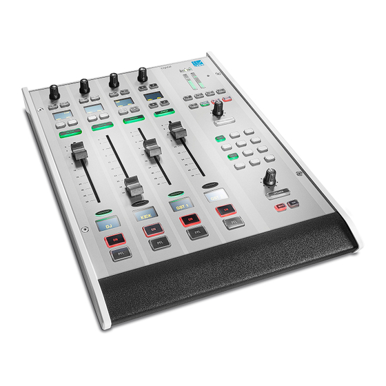
3. Product Overview Product Overview crystal standard configuration is a live mixing console for radio. It consists of three components: Compact Engine, crystal control surface and DisplayDock. The system is available in two editions: Fader Start or Button Start. The control surface comes in a range of frame sizes and connects to the Compact Engine via CAN bus. -
Page 7: The Hardware
4. The Hardware The Hardware This chapter describes the hardware components and options. Topics include: · Console Editions · Control Surface Variants · The Compact Engine crystal standard configuration User Manual Version: 6.4.0/4 7/149... - Page 8 4. The Hardware Console Editions crystal standard configuration is available in two editions: Fader Start (FS) and Button Start (BT). They differ in the following ways. Fader Strip Controls The two large keys at the bottom of the fader strip provide: ·...
- Page 9 (included). All frames include CAN IN and CAN OUT connectors for easy daisy-chaining. In each case, the CAN bus address of a module defines its functionality. Thus, frames can be wired in any order. Split-frame Example crystal standard configuration User Manual Version: 6.4.0/4 9/149...
- Page 10 All connectors are positioned along the top edge, so you must make sure that these are accessible: 8-fader Surface (top edge) 10/149 Version: 6.4.0/4 crystal standard configuration User Manual...
- Page 11 Fader Start: AES3 IO Card (952/32) - 4 x AES3 inputs and 4 x AES3 outputs. · Button Start: LINE IO Card (952/31) - 8 x line level inputs and 8 x line level outputs. crystal standard configuration User Manual Version: 6.4.0/4 11/149...
- Page 12 This is optional and must be ordered separately. If both inputs are connected, then the two feeds provide main and redundant power. The Compact Engine MUST be connected to the mains using the power cable supplied with the system. 12/149 Version: 6.4.0/4 crystal standard configuration User Manual...
-
Page 13: Specification
5. Specification Specification This chapter describes the system specification. Topics include: · Available Sources · Available Buses · Default Audio Assignments · GPIO Functions crystal standard configuration User Manual Version: 6.4.0/4 13/149... - Page 14 LINE 2 mono LINE INPUT (front) Inputs 1&2 û û û û LINE 3 ...4 mono " Inputs 3&4 ...5&6 ü ü ü û HYB 1 ...2 mono " Input 7 ...8 14/149 Version: 6.4.0/4 crystal standard configuration User Manual...
- Page 15 " " RAV CODEC 1 mono " " RAV CODEC 2 mono " " RAV CODEC 3 mono " " RAV CODEC 4 mono " " AES CODEC mono " " crystal standard configuration User Manual Version: 6.4.0/4 15/149...
- Page 16 Button Start Consoles only LINE INPUT (Compact Engine front expansion slot 2) Input Number Source Name Format LINE 2 left/right LINE 3 left/right LINE 4 left/right HYB 1 mono HYB 2 mono 16/149 Version: 6.4.0/4 crystal standard configuration User Manual...
- Page 17 LINE OUTPUT (Compact Engine front expansion slot 2) Output Number Local Matrix Name Format Default Audio from LINE 5 left/right AUX 1 LINE 6 left/right AUX 2 LINE 7 left/right LINE 8 left/right crystal standard configuration User Manual Version: 6.4.0/4 17/149...
- Page 18 AES3 OUTPUT (Compact Engine front expansion slot 2) Output Number Local Matrix Name Format Default Audio from AES 5 left/right AUX 1 AES 6 left/right AUX 2 AES 7 left/right AES 8 left/right 18/149 Version: 6.4.0/4 crystal standard configuration User Manual...
- Page 19 Channel Number Source Name Format 1/2... 63/64 MADI 1... MADI 32 left/right 5.3.8 MADI Outputs MADI 3 & 4 (Compact Engine front panel) Channel Number Format Default Audio from 1/2... 63/64 left/right crystal standard configuration User Manual Version: 6.4.0/4 19/149...
- Page 20 Logic REDLIGHT CR REDLIGHT STUDIO FADER START LINE 1 FADER START AES 1 HYBRID 1 ON HYBRID 1 (LOCAL) HYBRID 2 ON HYBRID 2 (LOCAL) PGM 1 SILENCE MIC 1 "ON" TALLY 20/149 Version: 6.4.0/4 crystal standard configuration User Manual...
-
Page 21: Installation
This chapter describes how to install the control surface and Compact Engine. Topics include: · Installing the Control Surface · Installing the Compact Engine · Grounding & Power · Wiring · Synchronization crystal standard configuration User Manual Version: 6.4.0/4 21/149... - Page 22 Please check the contents of the shipping boxes, and in the event of any transport damage, contact your local Lawo representative or email support@lawo.com. A list of serial numbers for all components is included with the shipment. Please keep this list for your records.
- Page 23 1 x USB memory card - containing marketing materials. Optional The following accessories can be ordered separately: · 1 x external 12V DC power supply (955/50-80) - to connect 12V DC power to the frame. crystal standard configuration User Manual Version: 6.4.0/4 23/149...
- Page 24 Please check the contents of the shipping boxes, and in the event of any transport damage, contact your local Lawo representative or email support@lawo.com. A list of serial numbers for all components is included with the shipment. Please keep this list for your records.
- Page 25 Connect the 12V DC power supply to the DC IN connector on the rear panel. Using the IEC cable provided, connect your AC mains to the PSU. The AC mains connection MUST be made using the power cable supplied with the system. crystal standard configuration User Manual Version: 6.4.0/4 25/149...
- Page 26 Connect the 12V DC power supply to the DC IN connector on the rear panel. Using the IEC cable provided, connect your AC mains to the PSU. The Compact Engine MUST be connected to the mains using the power cable supplied with the system. 26/149 Version: 6.4.0/4 crystal standard configuration User Manual...
- Page 27 The CAN bus can be hot-plugged, and so the cabling can be performed while the components are powered. The maximum length of the CAN bus connection is 60 meters. RS-422 (serial) The serial port is usually left unconnected. crystal standard configuration User Manual Version: 6.4.0/4 27/149...
- Page 28 6. Installation MADI (optical) In the crystal standard configuration, MADI ports 1 and 2 are not available for external use. They are used internally to support the RAVENNA IO card (5). MADI ports 3 (and 4) can be used to connect multi-channel digital audio to the system. The ports conform to AES10 and carry 64 bi-directional channels (at 48kHz).
- Page 29 In both cases, connections are made using standard 75 ohm BNC connectors. The maximum cable length depends on the equipment you are connecting to. Synchronization for more details. Grounding & Power Grounding & Power. crystal standard configuration User Manual Version: 6.4.0/4 29/149...
- Page 30 After a cold start, the internal generator will reset to the default value stored in the configuration (48kHz). Sync Output The WCLK OUT connector always provides an output of the current system reference. 30/149 Version: 6.4.0/4 crystal standard configuration User Manual...
-
Page 31: System Setup
Setting Up the Control PC · Configuring the System · Licensing · Editing the System IP Settings · Setting the System Date and Time · Setting the Time Zone · Setting Up RAVENNA/AES67 crystal standard configuration User Manual Version: 6.4.0/4 31/149... - Page 32 Using the IEC cable provided, connect the mains supply to the 100-240V AC input on the Compact Engine. The AC mains connections MUST be made using the power cables supplied with the system. 32/149 Version: 6.4.0/4 crystal standard configuration User Manual...
- Page 33 Remember to connect power to both the main surface and extender module (using the PSU's provided). The CAN bus must be terminated and so it is important to connect the full chain. Please do not attempt to operate the system with only an extender module connected! crystal standard configuration User Manual Version: 6.4.0/4 33/149...
- Page 34 The hardware components are now ready to be configured - this takes approximately 20 seconds from power Please note: if you perform a cold start, then the system ignores the warm start data and resets to the default values stored in the configuration. 34/149 Version: 6.4.0/4 crystal standard configuration User Manual...
- Page 35 Then check the network cabling and IP settings of the control PC and Compact Engine. If you are connecting via a larger network, you may need to consult your network administrator to gain access to the Lawo device. crystal standard configuration User Manual Version: 6.4.0/4 35/149...
- Page 36 When you reach the 'Summary' window, check the options and click Install - the software components are installed onto your computer; this may take a few minutes. By default, files are installed in the location: 'C:\Program Files\DisplayDock (Crystal)'. 36/149 Version: 6.4.0/4 crystal standard configuration User Manual...
- Page 37 When all of the components have been installed, the following window will appear: Select Finish to exit the setup wizard and launch the DisplayDock Admin tool. If you have any problems with the software installation, please contact your local Lawo representative or email support@lawo.com.
- Page 38 If the "Connection Status" remains as NOT connected, then there is a problem with the network communication. Check that the "Device IP Address" has been entered correctly. Then check the physical connections and the TCP/IP settings of your computer's Network Interface Card. 38/149 Version: 6.4.0/4 crystal standard configuration User Manual...
- Page 39 ("Connection Status" = NOT connected). After the restart, the program reconnects and checks the "Firmware" and "Config" statuses again. The "Firmware" status should now be up to date and you can continue on to the configuration. crystal standard configuration User Manual Version: 6.4.0/4 39/149...
- Page 40 ("Connection Status" = NOT connected). After the restart, the program reconnects and checks the "Config" status again. The status should now be up to date and you can continue on to the next task. 40/149 Version: 6.4.0/4 crystal standard configuration User Manual...
- Page 41 Click on an icon to select the monitor you wish to use - an ID appears briefly on the connected screen. Then close DisplayDock Admin to update the start script accordingly. When you next open the DisplayDock session, the GUI will appear on the selected monitor. crystal standard configuration User Manual Version: 6.4.0/4 41/149...
- Page 42 If you have purchased a dongle for DisplayDock, then this will have a metal "LAWO logo" tag attached as shown below. Multiple software products can be licensed from a single dongle.
- Page 43 To use this method, your PC must have an internet connection. If installing onto a dongle, then this should be connected to the PC's USB port. Open the Lawo licensing web page by copying the following URL into your web browser: https://licenseportal.lawo.com If necessary you can choose a different language using the drop-down menu at the top right of the page.
- Page 44 After selecting OK, a summary appears: You can now close the browser and return to your Lawo software application or install the USB dongle. For information on re-hosting a license, offline activation, backup/restore and using a license server, please...
- Page 45 Open a Telnet session to the crystal standard configuration system. Once login is complete, type in "chparm -ipaddr" (press ENTER) to start the set IP address script. When prompted, enter the new IP address for the system and press ENTER.
- Page 46 Right-click on the unit and select Set System Time. Then confirm by selecting OK. The software now sets the system date and time to match that of the control PC. The success (or failure) of the reset is shown in the SoP Explorer status area: 46/149 Version: 6.4.0/4 crystal standard configuration User Manual...
- Page 47 The time zone can be edited by opening a telnet session to the Compact Engine. Open a Telnet session to the crystal standard configuration system. Once login is complete, type "chparm -tz" (press ENTER). Select option 1 (press ENTER). When prompted, enter the new time zone rule and press ENTER.
- Page 48 Any settings changed from the RAVENNA Web UI can be backed up (and restored) using the "Backup & Restore Config" tool. This is ideal if you need to exchange an IO card or device. 48/149 Version: 6.4.0/4 crystal standard configuration User Manual...
- Page 49 Alternatively, open a web browser application and enter the IP address of the connected streaming port into the URL field. The default IP addresses are: · ETHERNET A = 192.168.101.250 · ETHERNET B = 192.168.110.253 crystal standard configuration User Manual Version: 6.4.0/4 49/149...
- Page 50 RAVENNA Web UI (Home page) Note that the Landing Page preview uses a static library image and does not update in real time or represent the actual settings on the connected device! 50/149 Version: 6.4.0/4 crystal standard configuration User Manual...
- Page 51 Default subnet mask = 255.255.255.0 Note that, in the RAVENNA Web UI, the two ports are labeled as follows: · ETHERNET A = streaming port ra0 · ETHERNET B = streaming port ra1 crystal standard configuration User Manual Version: 6.4.0/4 51/149...
- Page 52 Then select Reboot - the device must be rebooted before the new settings take affect, which means that you will lose your browser connection. Once the reboot is complete, re-open the RAVENNA Web UI to check the changes. 52/149 Version: 6.4.0/4 crystal standard configuration User Manual...
- Page 53 7.9.8 Synchronization (PTP) A crystal standard configuration system will automatically use the highest prioritized sync source (if a valid signal is present): MADI, Wordclock, AES3 or internal clock. Note that the MADI option actually means PTP, due to the internal workings of the system.
- Page 54 Once you have chosen a stream, click on Apply - the Rx stream name on the Home page updates to show the stream name in (). If the source RAV In 1 is assigned to a fader strip, then it should now be receiving some audio. 54/149 Version: 6.4.0/4 crystal standard configuration User Manual...
- Page 55 Tx Streams list when you open the RAVENNA Web UI Home page. Unless you wish to create additional Tx streams, there is no need to edit the configuration from the Web UI. RAVENNA Web UI (Default Stream Setup) crystal standard configuration User Manual Version: 6.4.0/4 55/149...
- Page 56 PTP signal. Hover your mouse over the graph to reveal further information. Ø Click on PTP to view or edit the PTP Properties for the device. 56/149 Version: 6.4.0/4 crystal standard configuration User Manual...
- Page 57 This area defines the sending streams, which are used to publish audio from the device to the network. The Tx streams are pre-defined by the crystal standard configuration. In each case, you will see the Tx stream name and the RAVENNA media channels which are being used.
- Page 58 You will also see an icon on the right of each Rx stream which reflects the same statuses. Click on the icon to open the Statistics window - this provides more information about the stream. Healthy Rx Stream (green) Unhealthy Rx Stream (orange) 58/149 Version: 6.4.0/4 crystal standard configuration User Manual...
- Page 59 Click on Reset Stats to clear the statistics history for the selected stream. Return to the Home page and click on the Reset button to clear the statistics history for all Rx streams. crystal standard configuration User Manual Version: 6.4.0/4...
-
Page 60: Operation
· Input Gain & Pan · DSP Parameters · Metering · Monitoring & Talkback · Master Functions · The Advanced Page · Editing User Labels · Conference Bussing (N-1/Mix Minus) · Snapshots 60/149 Version: 6.4.0/4 crystal standard configuration User Manual... - Page 61 · The network cabling and IP settings of the control PC, see Configuring the Network Settings on the · The IP address of the Compact Engine, see Editing the System IP Settings. crystal standard configuration User Manual Version: 6.4.0/4 61/149...
- Page 62 Other pages appear alongside the DOCK as needed. For example, press a fader strip ACCESS key and the "Source Parameters" page appears. In each case, the full-screen pages appear to the left of the DOCK, so that the DOCK remains accessible at all times. DOCK Source Parameters + DOCK 62/149 Version: 6.4.0/4 crystal standard configuration User Manual...
- Page 63 From the DOCK, select METERING to open the metering page: METERING + DOCK Click on the LAWO logo (top right) to open the advanced page: ADVANCED + DOCK You can change page using the PAGE UP and PAGE DOWN keys on your PC keyboard. This will scroll through all of the available pages.
- Page 64 Use the fader to adjust the source's mix level to the summing bus outputs. The level can be adjusted from - +9dB. Note that PGM buses are always fed post-fader, while AUX buses can be switched between pre- and post-fader. 64/149 Version: 6.4.0/4 crystal standard configuration User Manual...
- Page 65 To fade the level out, press ON and close the fader - the ON key cancels and the OFF key lights. If you keep hold of the fader you can re-open the channel without having to prime the ON key again. crystal standard configuration User Manual Version: 6.4.0/4...
- Page 66 CUE - press this key to cue a source pre-fader. See PFL / CUE for full details. On a Button Start console you can enable or disable automix from the Dynamics source parameter controls. 66/149 Version: 6.4.0/4 crystal standard configuration User Manual...
- Page 67 – press BUS and then select a page (1 to 5) to map bus assignments onto the Fader Module. Local Snapshots – press and hold UNLOCK + SNAP RECALL + a memory number (1 to 5) to recall settings from a local snapshot. SNAP STORE works in a similar manner. crystal standard configuration User Manual Version: 6.4.0/4 67/149...
- Page 68 For the Control Room and Studio outputs, the MUTE and DIM keys allow you to quickly mute or dim the volume of the loudspeakers. All of the monitoring functions are described in more detail later. 68/149 Version: 6.4.0/4 crystal standard configuration User Manual...
- Page 69 You cannot choose a red source as it is deemed to be on-air. In this instance, first find the source on the surface and close its fader - the button color changes from red to blue, and the source can be selected. crystal standard configuration User Manual Version: 6.4.0/4...
- Page 70 Is the source already assigned to a different fader strip and the fader open? If so, the source is deemed to be on-air, and so you must find the source and close its fader. 70/149 Version: 6.4.0/4 crystal standard configuration User Manual...
- Page 71 -120dB to +9dB. When you have finished editing the bus assignments, deselect BUS (on the Central Module) - the rotary controls and soft keys return to their default functions (described earlier). crystal standard configuration User Manual Version: 6.4.0/4 71/149...
- Page 72 8. Operation 8.6.2 Assigning a Bus to an Output By default, the summing buses are assigned to a number of physical outputs and Tx streams. These are listed under Default Audio Assignments. 72/149 Version: 6.4.0/4 crystal standard configuration User Manual...
- Page 73 To interrogate parameters without making a change, tap down on the rotary control without turning - the display will show the parameter and its current value. For more information on gain ranges and other input parameters, please see Input & Pan Parameters. crystal standard configuration User Manual Version: 6.4.0/4 73/149...
- Page 74 To turn off AutoGain, press the AUTOGAIN button again - the button changes color (blue = off). The mic gain now reverts to its previous value (before AutoGain was enabled), and MIC gain can be adjusted manually. 74/149 Version: 6.4.0/4 crystal standard configuration User Manual...
- Page 75 Each of the MIC sources comes fully-configured with analog and digital input sections; input meter; EQ & Filters; Dynamics (Compressor, Expander and Gate); De-Esser & AutoMix; and a Limiter. Other sources support a subset of these parameters. crystal standard configuration User Manual Version: 6.4.0/4 75/149...
- Page 76 The surface controls are paged through different parameter sets using the INP, DYN, LIM, DLY and EQ keys on the Central Module. Note that the rotary controls and soft keys across all 4 fader strips are utlised when working in this mode. 76/149 Version: 6.4.0/4 crystal standard configuration User Manual...
- Page 77 When you have finished adjusting the parameters, deselect the ACCESS key - the fader strip soft keys and rotary controls return to their default functions (described earlier), and the DisplayDock "Source Parameters" page closes. The next few topics describe the source parameters in more detail. crystal standard configuration User Manual Version: 6.4.0/4 77/149...
- Page 78 MIC gain, channel GAIN and PAN can also be adjusted from the fader strip rotary control (as described earlier). HYBRID Sources For a mono HYBRID source, only the digital domain parameters apply and so you can adjust PHASE reverse, channel GAIN and left/right PAN. 78/149 Version: 6.4.0/4 crystal standard configuration User Manual...
- Page 79 Left channel = L+R (M+S) · Right channel = L-R (M-S) By adjusting the BALANCE control, you can vary the ratio of Middle to Side, and thereby adjust the width of the stereo field. crystal standard configuration User Manual Version: 6.4.0/4 79/149...
- Page 80 Whenever the CR red light is active, the control room speakers will automatically mute (to prevent feedback from an open MIC). You can bypass this functionality by assigning the MIC source to the STUDIO red light. 80/149 Version: 6.4.0/4 crystal standard configuration User Manual...
- Page 81 Dynamics section: Compressor, Expander and Gate. This changes dynamically as the signal level varies, and so is extremely helpful when adjusting parameters. If a red ball is also visible, then this represents the output level of the De-Esser. crystal standard configuration User Manual Version: 6.4.0/4 81/149...
- Page 82 The characteristic of the compressor is optimized for radio on-air operation. The ratio pivot point moves around the working point according to the input signal level and not around a fixed threshold. This allows the ratio to adapt without having to change the level considerably. 82/149 Version: 6.4.0/4 crystal standard configuration User Manual...
- Page 83 Both DYN and EXP must be enabled (red) for the expander to be active. This is best checked by looking at DisplayDock (where you can see the DYN button plus on/off for the individual sections: COMP, EXP, GATE, etc.) crystal standard configuration User Manual Version: 6.4.0/4 83/149...
- Page 84 Both DYN and GATE must be enabled (red) for the expander to be active. This is best checked by looking at DisplayDock (where you can see the DYN button plus on/off for the individual sections: COMP, EXP, GATE, etc.) 84/149 Version: 6.4.0/4 crystal standard configuration User Manual...
- Page 85 Both DYN and DeEss must be enabled (red) for the de-esser to be active. This is best checked by looking at DisplayDock (where you can see the DYN button plus on/off for the individual sections: COMP, EXP, GATE, etc.) crystal standard configuration User Manual Version: 6.4.0/4 85/149...
- Page 86 Both DYN and AMix must be enabled (red) for AutoMix to be active. If the master DYN button is not enabled, then the AMix button is dim to indicate that AutoMix is not yet active. 86/149 Version: 6.4.0/4 crystal standard configuration User Manual...
- Page 87 This changes dynamically as the signal level varies, and so is extremely helpful when adjusting parameters. 8.8.7 Delay Delay is not supported by any source in the crystal standard configuration. Therefore, the DLY key on the Central Module has no function. crystal standard configuration User Manual Version: 6.4.0/4...
- Page 88 Press again to return to the 3-band parametric EQ (page 1). The EQ graph on DisplayDock shows all five bands of EQ simultaneously. This provides a great overview of the complete section. 88/149 Version: 6.4.0/4 crystal standard configuration User Manual...
- Page 89 For the GAIN/FREQ control, turn to adjust the Gain, and then press down and turn to adjust Frequency. The EQ button acts as the master on/off for the complete section: 3-band parametric EQ + 2-band filters. crystal standard configuration User Manual Version: 6.4.0/4...
- Page 90 For the GAIN/FREQ control, turn to adjust the Gain, and then press down and turn to adjust Frequency. The EQ button acts as the master on/off for the complete section: 3-band parametric EQ + 2-band filters. 90/149 Version: 6.4.0/4 crystal standard configuration User Manual...
- Page 91 On the control surface, each meter is accompanied by a stereo correlation meter. On DisplayDock, you also have loudness metering for PGM 1. On a 4-fader console, there is no second Central Module and so the PGM 1 meter appears on DisplayDock only. crystal standard configuration User Manual Version: 6.4.0/4 91/149...
- Page 92 The integrated loudness measurement is controlled by the on-screen Start, Stop and Reset buttons. It is very useful for measuring loudness over a longer period - for example, for the duration of the show. The measurement is displayed in LUFS (Loudness Units Full Scale). 92/149 Version: 6.4.0/4 crystal standard configuration User Manual...
- Page 93 1&2, RAVENNA Codec 1 to 4 or the AES Codec. Input Metering On the bottom row are 8 meters which are switched using the on-screen "Fader" buttons. This allows you to meter up to 24 faders (for a maximum size surface). crystal standard configuration User Manual Version: 6.4.0/4 93/149...
- Page 94 8. Operation 8.10 Monitoring & Talkback crystal standard configuration supports four stereo monitoring outputs: · MON CR - for the control room speakers. · MON STUDIO - for the studio speakers. · MON DJ - for the DJ headphones. ·...
- Page 95 MUTE and DIM keys allow you to quickly mute or dim the volume of the loudspeakers. The stereo PPM on the first Central Module follows the MON CR source selector. The meter shows the level before the Volume, Mute and Dim. crystal standard configuration User Manual Version: 6.4.0/4 95/149...
- Page 96 The extension will replace the PGM 1 metering and loudness controls, and be clearly labeled (e.g. CR for control room): DOCK (default) DOCK (with MON CR Extension) To close an extension, turn off its activation button - the DOCK returns to its default state (with PGM 1 metering). 96/149 Version: 6.4.0/4 crystal standard configuration User Manual...
- Page 97 = PFL (or CUE); right ear = the current monitor source (e.g. PGM 1). You can use this mode to monitor the main program output while cueing up another source (pre-fader). crystal standard configuration User Manual Version: 6.4.0/4 97/149...
- Page 98 Whenever PFL (or CUE) is active, the bus is switched to the control room speakers and DJ headphones. The monitor outputs will return to their active monitor source once all PFL (or CUE) selections are cleared. Select CLEAR PFL on the Central Module to cancel all active PFLs quickly. 98/149 Version: 6.4.0/4 crystal standard configuration User Manual...
- Page 99 11 hours, 49 minutes and 03 seconds. For greater visibility, the "seconds" are also represented by the blue line/circle around the circumference of the display. crystal standard configuration User Manual Version: 6.4.0/4...
- Page 100 "Faders up" or "Faders down" = the timer is set to AUTO mode and to count when any fader is open. · "Timer up" or "Timer down" = the timer is set to manual mode. 100/149 Version: 6.4.0/4 crystal standard configuration User Manual...
- Page 101 · START - starts the timer from the last stop position/time. · STOP - stops the timer. · RESET - resets the timer, either to 00:00 (count-up) or the Preset value (Count-down). crystal standard configuration User Manual Version: 6.4.0/4 101/149...
- Page 102 Depending on the mode, the timer will count-up from 00:00 or count-down from a Preset value (described later). Note that the current time remains on-screen until the timer is reset. To reset the timer, press the RESET key (on the Central Module). 102/149 Version: 6.4.0/4 crystal standard configuration User Manual...
- Page 103 For our example, the timer stops once all MIC source faders are closed. Note that the current time remains on-screen until the timer is reset. To reset the timer, press the RESET key (on the Central Module). crystal standard configuration User Manual Version: 6.4.0/4 103/149...
- Page 104 TEL key on the source's fader strip to answer the call. To support this function, the GPIO connector must be correctly wired as GPIs 7 and 8 are used to trigger the incoming calls. See GPIO functions Connector Pin-Outs. 104/149 Version: 6.4.0/4 crystal standard configuration User Manual...
- Page 105 The Advanced Page The Advanced page (on DisplayDock) provides access to the local matrix and global options. To open the page, click on the Lawo logo at the top right of the DOCK - the Advanced page appears in full- screen view:...
- Page 106 These buttons show the current status of the individual alarms. If an alarm is triggered, then the corresponding button starts to blink in red. You can press to acknowledge the alarm - the button changes to static red. Once the alarm is resolved, the button color turns black (off). 106/149 Version: 6.4.0/4 crystal standard configuration User Manual...
- Page 107 Note that you will need to press and hold UNLOCK (on the Central Module) before you can select DEFAULT (on the GUI). This prevents an accidental reset of the output matrix. crystal standard configuration User Manual Version: 6.4.0/4 107/149...
- Page 108 The Export button will save all labels into an .xml file. This allows to copy the file to another DisplayDock PC and then select Import to import the labels. When using import, the labels are applied to sources with an identical source Name field. 108/149 Version: 6.4.0/4 crystal standard configuration User Manual...
- Page 109 Close all three source faders. The CONF buttons become red and all sources will hear the conference bus minus themselves. In other words, they can hear each other, but not themselves, and chat off-air. crystal standard configuration User Manual Version: 6.4.0/4 109/149...
- Page 110 To cancel the conference for any of the sources, deselect the CONF button. The CONF buttons turn green (off) and the source’s monitor feed receives PGM 1 minus themselves at all times. 110/149 Version: 6.4.0/4 crystal standard configuration User Manual...
- Page 111 The five local snapshot memories always reset the console globally, and are stored, recalled and cleared using the keys on the Central Module. For each operation you will need to press UNLOCK to unlock SNAP RECALL and SNAP STORE. crystal standard configuration User Manual Version: 6.4.0/4 111/149...
- Page 112 Keep holding SNAP RECALL and SNAP STORE and select a memory - e.g. number 4. The snapshot memory if cleared. To check if the operation has been succesful, press and hold SNAP RECALL - the memory number should now be clear (unlit). 112/149 Version: 6.4.0/4 crystal standard configuration User Manual...
- Page 113 Enter a snapshot name (e.g. Guests Automix) and select OK - the window closes and the settings are saved. Note that the snapshot Group and Type cannot be changed. You can enter text to describe the snapshot into the Comment field if you wish. crystal standard configuration User Manual Version: 6.4.0/4 113/149...
- Page 114 Enter a snapshot name (e.g. Mic DJ) and select OK - the window closes and the settings are saved. Note that the snapshot Group and Type cannot be changed. You can enter text to describe the snapshot into the Comment field if you wish. 114/149 Version: 6.4.0/4 crystal standard configuration User Manual...
- Page 115 To load either a Full or Source snapshot: Select LOAD SNAP - the "Load Snapshot" window appears: This window lists all of the snapshots stored in the current user group. In a crystal standard configuration system, one group is available: User Snapshots.
- Page 116 DisplayDock software, the file can be found at: C:\ProgramData\DSA\DisplayDock (Crystal)\database\VisConfigurations.mdb If you wish to backup your DisplayDock snapshots, then make a copy of the file and store it in a secure location. 116/149 Version: 6.4.0/4 crystal standard configuration User Manual...
-
Page 117: The Web Ui
9. The Web UI The Web UI This chapter describes the Web UI. Topics include: · Introduction · Opening a Session · The System Page · TCP Connections crystal standard configuration User Manual Version: 6.4.0/4 117/149... - Page 118 The Web UI provides status information about the system. It is accessed by entering the IP Address of the Compact Engine you wish to examine into a Web browser. The computer you use must be part of the same network and subnet as the Compact Engine. 118/149 Version: 6.4.0/4 crystal standard configuration User Manual...
- Page 119 Some of the information is displayed as a "snapshot" of the current data, which is only as current as the latest refresh. So, remember to use your browser's Refresh function, or click on Refresh, to keep up to date. crystal standard configuration User Manual Version: 6.4.0/4 119/149...
- Page 120 User Level - the user mode which created the configuration (in the On Air Designer configuration software). · Setup download from - the IP address of the computer used to load the On Air Designer configuration. 120/149 Version: 6.4.0/4 crystal standard configuration User Manual...
- Page 121 If enable = 1, then the sync source is enabled in the configuration. o If active = 1, then this is the active sync source for the system. · Sampling Rate – the operating frequency for the system (e.g. 48kHz). crystal standard configuration User Manual Version: 6.4.0/4 121/149...
- Page 122 · Date – the date and time at which the software running on the module or panel was created. · Version – the version of software running on the module or panel. 122/149 Version: 6.4.0/4 crystal standard configuration User Manual...
- Page 123 9. The Web UI 9.3.7 Client Connections The Client Connections show all network clients connected to the system. For example, the IP Addresses of any networked sapphire, crystal, Nova29, etc. crystal standard configuration User Manual Version: 6.4.0/4 123/149...
- Page 124 This page displays the network connections to the Compact Engine, and the state of those connections: · Netcom Connections - systems connected via GNET (GPIO Network). · DMS Connections - systems connected via DMS, for example VisTool PCs. · EmBER+ Connections - EmBER+ consumers and providers. 124/149 Version: 6.4.0/4 crystal standard configuration User Manual...
-
Page 125: Maintenance
10. Maintenance Maintenance This chapter describes the maintenance procedures available for the system. Topics include: · Restarting the System · Compact Engine Procedures · Control Surface Procedures · Cleaning the Devices crystal standard configuration User Manual Version: 6.4.0/4 125/149... - Page 126 The exception is the Nova29 which must be cold started by opening a telnet session. A cold start will reboot the device. Do NOT perform a cold start while live on air! 126/149 Version: 6.4.0/4 crystal standard configuration User Manual...
- Page 127 At the end of the boot-up, the status display shows that the unit is now in “boot” mode (in the bottom left-hand corner): Press the >> button to page through the available diagnostics. When you have completed your tests, you can return the device to normal operation by pressing the recessed RESET button. crystal standard configuration User Manual Version: 6.4.0/4 127/149...
- Page 128 The unit will continue to boot in default mode, until you reset the Load Default Parms option. So repeat steps 1 to 3 but this time select the NO option (in step 2) to reinstate the stored IP address and configuration. 128/149 Version: 6.4.0/4 crystal standard configuration User Manual...
- Page 129 The MADI daughter board can be exchanged by removing the top cover. You MUST disconnect the unit from its power source to perform these operations. For more information on servicing other components, please contact your local Lawo representative or email support@lawo.com.
- Page 130 The session opens, and you will see the command prompt for the control system. Now follow the specific instructions for the task you wish to perform. The telnet password can be changed from the Web UI (via the System -> Control tab) in Administrator mode. 130/149 Version: 6.4.0/4 crystal standard configuration User Manual...
- Page 131 Set up the Serial connection for the COM port using the following credentials. · Speed: 115200 baud · Data bits: 8 · Stop bits: 1 · Parity: none · Flow control: none Now follow the specific instructions for the task you wish to perform. crystal standard configuration User Manual Version: 6.4.0/4 131/149...
- Page 132 This allows fast replacement of a frame in the case of a hardware failure. Providing the replacement frame is set to the correct CAN bus addresses, it will immediately take over the same functions as the exchanged frame. 132/149 Version: 6.4.0/4 crystal standard configuration User Manual...
- Page 133 10. Maintenance 10.4 Cleaning the Devices Lawo radio products are made from a variety of different materials, and each material might have specific cleaning requirements. Therefore, a general allowance for disinfection of product surfaces with disinfectants containing alcohol cannot be given.
-
Page 134: Appendices
This chapter includes further information which you may find useful. Topics include: · Part Numbers · System Reference Levels · Connector Pin-Outs · crystal Surface Power Supply · Compact Engine Power Supply · Advanced Licensing Features 134/149 Version: 6.4.0/4 crystal standard configuration User Manual... - Page 135 Further technical information can be found in the product data sheets. The system part numbers will help you locate the data sheets for the main system components. All documentation is available from the Downloads area at www.lawo.com (after Login). crystal standard configuration User Manual Version: 6.4.0/4 135/149...
- Page 136 Then save and transfer the edited configuration to the DSP Core. For more information about the configuration tool, please see the "ON-AIR Designer User Guide". This is available from the Downloads area at www.lawo.com (after Login). 136/149 Version: 6.4.0/4 crystal standard configuration User Manual...
- Page 137 11. Appendices 11.3 Connector Pin-Outs crystal standard configuration User Manual Version: 6.4.0/4 137/149...
- Page 138 Max. Unit Input Voltage Frequency Input Current Inrush Current cold start at 25°C full Load 30A/100V 60A/240V Efficiency at 115 V & 230 V Output Voltage 12±5% Output Current Leakage Current <3.5 138/149 Version: 6.4.0/4 crystal standard configuration User Manual...
- Page 139 Cable length without plug 1200 Electrical Specification Parameter Conditions Min. Typ. Max. Unit Input Voltage Frequency Input Current 1,85A/115V 1A/230V Inrush Current 120A/230V Efficiency Output Voltage 12±5% Output Current 11.5 Leakage Current 0,75 crystal standard configuration User Manual Version: 6.4.0/4 139/149...
- Page 140 · Open the 'Lawo License' web browser page at https://licenseportal.lawo.com. · Copy your license ticket number - this is the 25 number code - into the Ticket field and select Next. At the "My Licenses" summary window, select Re-Host Licenses: Make sure that the Cm container is connected to the computer, select the licenses you wish to re-host and select Deactivate Selected Licenses Now.
- Page 141 Create a license request file - for the Cm storage container. Then copy the file onto a computer with internet access. · Activate the license - using the 'Lawo License' web portal, copy the license update file back to the original computer. ·...
- Page 142 11. Appendices At this stage, there are two additional steps (to add the correct firmcode) if you have selected a CmStick container. Enter the following Lawo FirmCode to create the license request file: Select Add license of a new producer Enter the Lawo FirmCode = 102037 Select Next, and using Windows Explorer, enter a file path for the license request file.
- Page 143 On a computer with internet access, follow the first four steps from the online activation method: · Open the 'Lawo License' web browser page at https://licenseportal.lawo.com. · Copy your license ticket number - this is the 25 number code - into the Ticket field and select Next. ·...
- Page 144 Download the update: Select Download License Update File Now and, when prompted, choose the Save file option - the file is downloaded. Copy the License Update file back to the original PC. 144/149 Version: 6.4.0/4 crystal standard configuration User Manual...
- Page 145 Select Commit to action the update - the license is activated and you can close the 'CodeMeter Control Center'. You can now return to your Lawo application or install your USB license dongle - all licensed features should be available.
- Page 146 A new local computer container is created each time you run the CodeMeter Runtime install wizard. Therefore, if you have installed multiple Lawo products or software versions, you will see several LAWO AG containers. If a USB dongle is connected, you will see a container labelled CmStick.
- Page 147 This license storage method can be used to administrate licenses centrally within a local network. For example, when starting a Lawo application such as VisTool, the local computer asks the server to borrow the relevant license. The license is then used by the VisTool client until the application is closed. On closing, the license is handed back to the server where it may then be used by a different VisTool client.
- Page 148 Under Configuration -> Network, add the correct IP settings into the Server Search list: Click Apply and restart the CodeMeter Runtime software. Note that once the Server Search list has an entry, all other license servers (announced automatically to the network) will be ignored. 148/149 Version: 6.4.0/4 crystal standard configuration User Manual...
- Page 149 Under Content -> Licenses, choose the CmContainer (holding the server licenses) and select the desired license file: If the licenses is in use, then a warning message appears. You can check which licenses are available (free) by selecting Server and Cluster: crystal standard configuration User Manual Version: 6.4.0/4 149/149...
Need help?
Do you have a question about the Crystal standard configuration and is the answer not in the manual?
Questions and answers