Table of Contents
Advertisement
Quick Links
Advertisement
Table of Contents

Related Manuals for LAWO mc266


Summary of Contents for LAWO mc266
-
Page 1: Tutorial
mc²66 Tutorial Version: V1.3/0 Edition: 05-12-14... - Page 2 All entries in this document have been thoroughly checked; however no guarantee for correctness can be given. Lawo AG cannot be held responsible for any misleading or incorrect information provided throughout this manual.
-
Page 4: Table Of Contents
Table of Contents Table of Contents TUTORIAL TABLE OF CONTENTS PREFACE About This Manual Conventions Headings Instructions and Results Marginal notes Action Buttons CHAPTER 1: TUTORIAL Welcome Control Surface Overview Signal Flow The Power of Layering Integrated Digital Routing Matrix Console Reset Timecode Automation ACCESS CHANNEL/ASSIGN and SCREEN CONTROL... - Page 5 Table of Contents Routing Masters to Output Destinations Using Auxiliary Sends Creating a Mix Minus (N-1) Configuring the Mix Minus Auxiliary Sends Activating the Mix Minus Sends Using VCA Grouping Assigning VCA Masters to the Control Surface Assigning Channels to a VCA Master Applying Signal Processing Using the 4-band Equaliser Using the High and Low Pass Filters...
- Page 6 Table of Contents mc²66 V1.3/0 7/ 68...
-
Page 7: Preface
Preface Preface About This Manual Before we guide you through the operation of the mc 66 broadcast production console, first a few words about this manual. Chapter 1 provides a step-by-step tutorial to common console operations. If you are new to the console, please read this chapter first. -
Page 8: Action Buttons
Preface Action Buttons We will also be using some conventions to help distinguish explanatory text from the text referring to items on the console: Silk screened text on the console’s front panel is referred to in UPPERCASE and button cap engravings are written in bold –... -
Page 10: Chapter 1: Tutorial
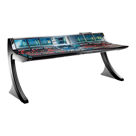
Tutorial Tutorial Welcome Welcome to the mc 66 Broadcast Production Console, Lawo’s purpose designed solution for on-air and live-to-tape broadcast operations. The mc 66 is a very flexible mixing console with the power to deal with a range of production types. This tutorial guides you step-by-step through some of the principal console operations. -
Page 11: Signal Flow
Tutorial Signal Flow The mc 66 provides the flexibility to configure as many input Fully Featured Channel Signal Flow: channels, monitor return channels, groups, sums (main mix outputs) and auxiliary sends as the production requires. In addition, these resources can be allocated full signal processing INMIX INMIX or reduced signal processing enabling you to assign EQ,... -
Page 12: The Power Of Layering
Tutorial The Power of Layering The console’s control surface includes both channel and main Channel Fader Strips fader strips. Any fader strip may control any type of channel - input, monitor return, group, sum, auxiliary or VCA master – allowing you to lay out your source channels and output masters where you want them. -
Page 13: Integrated Digital Routing Matrix
Tutorial Integrated Digital Routing Matrix In addition to powerful mixing features, the console includes an integrated digital routing matrix: Any source may be routed to any channel, and any output mix routed to any destination. In addition, you may route sources directly to destinations, for example to feed a Mic/Line input to an AES output for archive recording purposes. -
Page 14: Console Reset
Tutorial Console Reset One of the major benefits of the mc 66 is the ability to store and recall all the settings required for a live show or type of application. Productions form the top level for user data storage and store the settings required for a production or type of job. -
Page 15: Timecode Automation
Tutorial Timecode Automation The mc 66’s automation system provides the ability to automate console settings referenced to timecode. Note that in addition to providing automation of channel parameters such as faders, mutes, aux sends, EQ, etc., the system allows you to automate other settings such as bus routing, channel signal flow, etc. -
Page 16: Access Channel/Assign And Screen Control
Tutorial ACCESS CHANNEL/ASSIGN and SCREEN CONTROL Located in the centre section of the console are two very important control areas used throughout the operation of the console: The ACCESS CHANNEL/ASSIGN control panel is used for • a variety of tasks including Central Control Section, bus and fader strip assignments. -
Page 17: The Access Channel/Assign Control Panel
Tutorial The ACCESS CHANNEL/ASSIGN control panel The ACCESS CHANNEL/ASSIGN control panel is located in the centre section of the console beneath the BANK and LAYER switching buttons: The panel consists of: Ten channel type selection buttons – INPUT, MON, AUX, •... - Page 18 Tutorial There are three ways in which you can modify the channel in access providing that the LOCK ACC (lock access) button is not selected: Press the SEL button on a channel or main fader strip. This is the simplest method for accessing channels on the active control surface.
- Page 19 Tutorial The third method of changing the channel in access is to increment or decrement the current channel number: Press the NEXT or PREV buttons to increment or • decrement the channel number by DSP type. For example, to scroll up or down through Input channels 1- 192, Monitor channels 1-96, Groups 1-48, Sums 1-48, Auxes 1-32, VCA Masters 1-16 and General Purpose Channels (GPCs) 1-256:...
-
Page 20: Screen Control
Tutorial SCREEN CONTROL The SCREEN CONTROL panel is located in the centre section of the console beneath the joystick, and works in conjunction with the centre control screen and keyboard, located in the console arm rest or connected to the keyboard USB port, to provide screen-based control for a variety of functions. - Page 21 Tutorial The SCREEN CONTROL buttons provide access to: Press SIGNAL to page between two displays: Signals - controls signal routing • Settings - adjusts I/O parameters • The MATRIX button is reserved for future implementation. Press BUS to view the Bus Assignments for a channel Press DSP CONFIG to view or change the DSP Configuration Press CHAN/CONFIG to page between two displays:...
- Page 22 Tutorial The area of the display outlined by the dotted black and • white line is ‘in focus’. By focussing on different sections of the display, you can change the soft key functions, located above the trackball, in order to perform different operations.
- Page 23 Tutorial To make a selection on a display, you may use the trackball, navigation buttons or rotary scroller: To use the trackball, position the cursor above the box you wish to select, and then press either the left or the right select button beneath the trackball: The display entry, for example AES3_003, highlights in black and is ready for the next operation.
- Page 24 Tutorial Having selected an entry on the display, the four soft keys above the trackball are used to action operations. Note that their functions vary depending on the display selection. For example: Select the Snapshots display by pressing the SNAP/SEQUENCE button. The soft keys update to provide LOAD, SAVE and UPDT functions as indicated in the alphanumeric displays.
-
Page 25: Entering Names From The Keyboard
Tutorial Entering Names from the Keyboard The keyboard is used for naming display entries, such as a console snapshot. You may also connect an external keyboard using the USB ports in the front arm rest of the console. Press the SCREEN CONTROL SNAP/SEQUENCE button to view the Snapshots display and, using either the trackball or navigation buttons, select a snapshot to rename. -
Page 26: Getting Started
Tutorial If you make a mistake or want to exit the naming mode, press the Esc button on the keyboard or deselect the EDIT button. Getting Started Having covered some of the concepts behind the mc 66, let’s look at how to get started on the console. We are assuming that your console is fully commissioned such that all of the basic configuration tasks are complete. -
Page 27: Loading A Setup Production
Tutorial From power on, the console’s control system boots in a few seconds; during this time the centre control screen reports back on the boot-up progress. At the end of boot-up, the control system automatically loads the following: Configuration data – these are fixed settings specific to •... - Page 28 Tutorial To load a production: Press the PROD FILE button, located on the SCREEN CONTROL panel in the centre section of the console. The Production display appears on the centre control screen: The Production display is divided into two main areas: at the top of the display you will see the name of the Active production;...
-
Page 29: Interrogating The Channel Fader Strips
Tutorial Interrogating the Channel Fader Strips Depending on the settings within the setup production, you may now be able to open the faders and monitor audio! Don’t worry if this is not the case as we will look at how to modify the configuration shortly. - Page 30 Tutorial To switch between layers within a bank: Fader Strip Press the 2ND button located on the fader strip to switch an individual strip. The fader’s label, control positions and Channel display update to reflect the settings for the second layer. If there is nothing assigned to this layer, then you will switch to a blank fader strip.
-
Page 31: Creating Your Own Configuration
Tutorial Creating Your Own Configuration Having loaded a setup production, you will want to modify the configuration to suit your particular show or mix. You can perform these operations in any order, but the most efficient way is as follows: Select the DSP configuration –... - Page 32 Tutorial Now press the global ASSIGN button, located on the STRIP ASSIGNMENT: ASSIGN MODES panel: The ASSIGN button flashes, and across the console the fader SEL buttons flash, in green, to indicate possible destinations for your selected channel: Press the fader SEL button on main fader strip 8 to complete the assignment.
- Page 33 Tutorial With the ASSIGN mode still active, now assign input channels 1-24 onto the control surface: Select INP 1 from the ACCESS CHANNEL/ASSIGN control panel by pressing INPUT, the number 1 and the Enter button. This puts input channel 1 into access; the CHANNEL and LABEL displays show the name and label for input channel 1.
-
Page 34: Source Routing
Tutorial Source Routing Now let’s route a new audio source, for example a CD player, into input channels 23 and 24. Press the SIGNAL button, located on the SCREEN CONTROL panel, to view the Signals display: Note that each time you press the SIGNAL button you toggle between two pages –... - Page 35 Tutorial Fader Strip To make the route press the CONN (Connection) soft key located above the trackball. The Signals display updates with a green line showing the route between AES301 and INP23. Look at fader strip 23 on the control surface; the fader strip and Channel display name and labels update and hopefully you are metering some audio: Repeat steps 3 to 5 to route the right hand side of the CD...
-
Page 36: Bus Assignments
Tutorial Bus Assignments Next we need to assign input channels 23 and 24 onto our main output (SUM 1). We may use either forward or reverse bus assign to perform this operation; let’s use reverse bus assign: First select the destination (Sum 1) by pressing the SEL button on the main fader strip controlling SUM 1 –... -
Page 37: Control Room Monitoring
Tutorial Control Room Monitoring The final step before we can hear our audio is to look at the control room monitoring. Both main and alternate monitor outputs controlled from CONTROL ROOM MONITORING panel: Press one of the 24 pre-programmed buttons to select SUM 1 as your monitor source. -
Page 38: Afl & Pfl Monitoring
Tutorial AFL & PFL Monitoring At any stage, you may listen to the output of a channel using Fader Strip the AFL and PFL buttons: To monitor the channel post fader, press the AFL button located on the fader strip. To listen to the channel pre fader, press PFL. -
Page 39: Routing Sources To Multiple Channels
Tutorial Routing Sources to Multiple Channels Next let’s assign some microphone sources to more of our input channels. For example, mic/line sources 1-8 to input channels 1- Press the SIGNAL button, located on the SCREEN CONTROL panel, to view the Signals display: Using the trackball or navigation buttons, select the source directory (e.g. - Page 40 Tutorial Now press the PAGE button, located above the trackball, to access the second page of soft key functions. The displays above the four soft keys update to show EDIT and STEP functions. Press the STEP button to activate the step forward mode. Now deselect PAGE and press the CONN soft key to make the first route.
-
Page 41: Controlling Microphone Pre-Amplifier Settings
Tutorial Controlling Microphone Pre-amplifier Settings Each microphone pre-amplifier may be remotely controlled in order to set input gain, phantom power, etc. prior to analogue- to-digital conversion. These settings may be controlled either from the fader strip or the Central Control Section. Let’s use the dedicated controls on the channel fader strip: Use the GAIN control to remotely set the microphone preamplifier gain. -
Page 42: Saving Your Settings
Tutorial Saving Your Settings Console settings are saved within productions onto the internal user data flash card. Each time you update a production you store a one-shot memory of the current console status, including low level settings such as DSP configuration, and high level settings such as your mix and console layout. - Page 43 Tutorial Using the trackball or navigation buttons focus on the list of productions in the lower part of the display. The four soft key functions update to show LOAD, NEW and SAVE. Press the SAVE soft key to save the current console settings into a new production: A new entry appears in the productions list with a default name (e.g.
-
Page 44: Renaming The Production
Tutorial Renaming the Production To rename the production: Using the trackball or navigation buttons focus on the Active production name at the top of the display. Press the PAGE button, located in the middle of the SCREEN CONTROL soft keys, to access the second level of soft key functions. -
Page 45: Updating The Production
Tutorial Updating the Production You should save your settings regularly as you work by updating the Active production. Note that updating overwrites the production data. Therefore, make sure that you have selected the correct production to Note update. To avoid accidental updates, always protect setup or template productions. -
Page 46: Configuring Audio Sub Group Masters
Tutorial Configuring Audio Sub Group Masters So far, we’ve routed our input channels directly to a main sum output. However, for many productions, you will want to use groups either to create independent mixes, like an international version, or to provide greater control over separate elements of the mix, for example to compress all of the music channels separately to the main presenter’s microphones. - Page 47 Tutorial The FADER button flashes, and across the console the fader SEL buttons flash, in green, to indicate possible sources for the chosen destination: Note that the SEL buttons on the first eight faders strips (INP 1 to INP 8) are illuminated in red showing that they are already assigned to the selected sum master.
- Page 48 Tutorial Now, we need to assign input channels 1-8 to one of the groups – let’s use Group 1: Select the destination (Group 1) by pressing the SEL button on the main fader strip controlling GRP 1: This puts GRP 1 into access as indicated on the ACCESS CHANNEL/ASSIGN control panel’s CHANNEL and LABEL displays.
-
Page 49: Monitoring The Group Output
Tutorial Monitoring the Group Output Your Control Room Monitor output should still be selected to SUM 1, so push open all the faders and you will be hearing a mix of your microphone channels (input channels 1 to 8) and the CD player (input channels 23 &... -
Page 50: Creating Stereo Channels Or Masters
Tutorial Creating Stereo Channels or Masters Up until now, we have been dealing with mono input channels, mono groups and a mono sum. However, any of theses channels may easily be changed from mono to stereo either from the Central Control Section or Signals display. For example, to change SUM 1 from mono to stereo: Press the SEL button on the main fader strip controlling SUM 1 to assign it to the Central Control Section. -
Page 51: Routing Masters To Output Destinations
Tutorial Routing Masters to Output Destinations So far we have looked at how to route sources into channels, assign channels to group and sum masters, and monitor the various paths. Next let’s look at how to assign your groups and sum output to new destinations, for example to feed a recorder or distribution chain. - Page 52 Tutorial To make the route press the CONN (Connection) soft key located above the trackball. The Signals display updates with a green line showing the route between SUM1 and AES3_001. Repeat steps 3 to 5 to route the right hand side of the stereo sum master (SUM2) to AES3_002.
-
Page 53: Using Auxiliary Sends
Tutorial Using Auxiliary Sends Auxiliary sends may be used for a variety of applications such as cue feeds, effects sends, mix minus (N-1) sends, etc. Depending on your choice of DSP configuration, each channel may access up to 32 sends. Send controls are paged onto the eight rotary encoders within the Central Control Section. -
Page 54: Creating A Mix Minus (N-1)
Tutorial Creating a Mix Minus (N-1) One of the most common functions required during a live production is the mix minus, or N-1, output. The mc 66 may use any of its 32 auxiliary sends to create mix minus feeds. Let’s take an example where we wish to create separate mix minus feeds for the first four microphone inputs we assigned to fader strips 1 through 4 earlier. - Page 55 Tutorial Now press the SCREEN CONTROL SIGNAL button again to switch to the Settings display: Your selected source name and label (e.g. MIC_06.3) are shown in the Selection box at the top left of the display, and a list of the current destinations for this source in the Destinations list below.
- Page 56 Tutorial Having configured a link between the input sources and mix minus auxiliary sends, now return to the Signals display by pressing the SIGNAL button again. The next step is to route the output of the auxiliary sends to the relevant mix minus destinations.
-
Page 57: Activating The Mix Minus Sends
Tutorial Activating the Mix Minus Sends Having configured auxiliary sends 1, 2, 3 and 4 to provide mix Fader Strip minus feeds for Microphone Inputs 1 to 4: Go to the fader strips controlling MIC 1 to 4 and press the CONF buttons on all four channels. -
Page 58: Using Vca Grouping
Tutorial Using VCA Grouping A common application for the eight main fader strips is to use them as VCA group masters. The console supports up to 16 dedicated VCA masters and you may assign any number of fader strips to a dedicated VCA. This provides the ability not only to control input and monitor channels but also groups, sums and auxiliary masters. -
Page 59: Assigning Channels To A Vca Master
Tutorial Assigning Channels to a VCA Master Let’s assign our CD player, on input channels 23 and 24 to VCA master 1: Press the fader SEL button on the fader strip controlling VCA 1. This puts VCA 1 into access as indicated on the ACCESS CHANNEL/ASSIGN control panel’s CHANNEL and LABEL displays. -
Page 60: Applying Signal Processing
Tutorial Applying Signal Processing Depending on your choice of DSP configuration, full signal processing may be available on your input channels, monitor return channels, groups, sums and/or auxiliary masters. This allows you to compress a group output or EQ an auxiliary master in the same way you would apply signal processing to an input channel. - Page 61 Tutorial If not already selected, press the CHAN/CONFIG button, located on the centre section SCREEN CONTROL panel, to view the Main display: The Main display is divided into the same sub sections as the Central Control Section front panel. As you adjust controls, the display updates to reflect your settings.
-
Page 62: Using The 4-Band Equaliser
Tutorial Using the 4-band Equaliser Locate the SCF/FILTER/EQUAIZER panel on the Central Control Section: At the bottom of the panel, press the EQ DISP button to display the 4-band equaliser on the four sets of GAIN, FREQ and Q controls. Turn on the master EQ ON button. -
Page 63: Using The High And Low Pass Filters
Tutorial Using the High and Low Pass Filters At the bottom of the SCF/FILTER/EQUALIZER panel, press the FILTER DISP button to switch the four sets of GAIN, FREQ and Q controls to the 2-band filter section. Controls on the left side of the panel now adjust the high pass filter, and controls on the right side adjust the low pass filter. -
Page 64: Setting A Compressor
Tutorial Setting a Compressor The console provides four independent blocks of dynamics Central Control Section processing (Gate, Expander, Compressor and Limiter). Any of the four sections may be placed anywhere within the channel signal flow. For example, to gate pre EQ and compress post EQ, or to limit the channel signal post fader while compressing the feed to the direct output. -
Page 65: Inserting Channel Delay
Tutorial Central Control Section Inserting Channel Delay To apply delay to a channel, for example to compensate for video processing delays: Locate the DAMP/DELAY/INS/DIROUT panel on the Central Control Section. Press the DLY button to assign the controls to the channel delay audio module. - Page 66 Tutorial The insert send and return assignments are made from the Signals display: Press the SIGNAL button, located on the SCREEN CONTROL panel, to view the Signals display. Using the trackball or navigation buttons, select the source directory (e.g. Insert Send), sub-directory (e.g. InsSnd Inp 1-24) and source (e.g.
- Page 67 Tutorial Repeat steps 2 to 4 to route the line input from the compressor (e.g. ANA13.1) to the insert return (INP1i): The Signals display updates with a green line showing the route between the source and destination. 68/ 68 V1.3/0...
-
Page 68: Assigning The Fader Strip Free Controls
Tutorial Assigning the Fader Strip Free Controls On each channel fader strip are four, and on each main fader strip two, assignable Free Controls. These provide local channel access to settings such as EQ, Panning, Dynamics, Auxiliary Sends, etc. Each control is touch sensitive and when turned provides fine control.
Need help?
Do you have a question about the mc266 and is the answer not in the manual?
Questions and answers