
Related Manuals for BEFCO CYCLONE FLEX 312-FLX


Summary of Contents for BEFCO CYCLONE FLEX 312-FLX
- Page 1 BEFCO ® Operator’s Manual CYCLONE FLEX Gang Grooming Mower 312-FLX, 315-FLX, 317-FLX The operator’s manual is a technical service guide and must always accompany the machine. Manual 961-207B May 2020...
-
Page 2: Signal Words
SAFETY Take note! This safety alert symbol found throughout this manual is used to call your attention to instructions involving your personal safety and the safety of others. Failure to follow these instructions can result in injury or death. This symbol means: ATTENTION! BECOME ALERT! YOUR SAFETY IS INVOLVED! - Page 3 4.06 - Drivelines and Center Gearbox Timing 4.07 - Transport 4.08 - Storage 5 - REPAIR PROCEDURES 5.01 - Gearbox 5.02 - Blade Spindle 5.03 - Suggested Spare Parts 6 - TROUBLESHOOTING 7 - PRE-DELIVERY CHECKLIST 8 - WARRANTY BEFCO NDEX...
-
Page 4: General Information
It is in your best interest to insure that this has been done. Warranty does not cover the following: 1. Cleaning, transporting, mailing and service call charges. See Chapter 8 - Warranty. BEFCO ENERAL NFORMATION... -
Page 5: Model And Serial Number Id
Attached to the frame is an ID plate showing the model and the serial number. Record your implement model and serial number in the space provided below. Your dealer needs this information to give you prompt, efficient service when you order parts. BEFCO ENERAL NFORMATION... -
Page 6: Safety Precautions
6. Operate only in daylight or good artificial light. 7. Ensure mower is properly mounted, adjusted and in good operating condition. 8. Ensure that all safety shielding and safety signs are properly installed and in good condition. BEFCO AFETY RECAUTIONS... -
Page 7: Starting And Stopping
8. Securely support mower before working underneath. 9. Lock up raised wing mower decks before transport (see fig. 14). Additional warning and operating decals are available at no extra charge. Please specify model and serial number when ordering. BEFCO AFETY RECAUTIONS... - Page 8 ’ YCLONE PERATOR ANUAL Fig. 2 - Safety decals, main frame; replace immediately if damaged. left side right side Yellow reflective decal Red reflective decal BEFCO AFETY RECAUTIONS...
- Page 9 ’ YCLONE PERATOR ANUAL Safety decals, decks; replace immediately if damaged. placed under belt shields placed under belt shields BEFCO AFETY RECAUTIONS...
- Page 10 ’ YCLONE PERATOR ANUAL Safety decals, drivelines; replace immediately if damaged. placed on outer shield placed on outer tube BEFCO AFETY RECAUTIONS...
-
Page 11: Operational Safety
1. The use of this equipment is subject to certain hazards which cannot be prevented by mechanical means or product design. All operators of this equipment must read BEFCO PERATION... - Page 12 18. Stay alert for holes, rocks and roots in the terrain and other hidden hazards. Keep away from drop-offs. 19. Use extreme care and maintain minimum ground speed when transporting on hillside, over rough ground and when operating close to ditches or fences. Be careful when turning sharp corners. BEFCO PERATION...
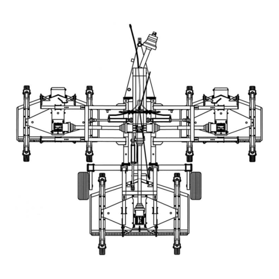
- Page 13 (see fig. 3): 1. Position the mower decks complete with hitches (#8) near the telescoping lift arms (#1) which are bolted into the lift arms. See Chapter 4 - Maintenance. See Chapter 7 - Pre-Delivery Checklist. BEFCO PERATION...
- Page 14 6. Using the grease fitting (#6) on the tube welded to the hitch (#9), grease the hitch pin and formed hitch plates. 7. See additional instructions below to set telescoping lift arms to proper operating width. Fig. 3 - Mowing unit assembly. BEFCO PERATION...
- Page 15 312-FLX & 315-FLX To mower deck telescoping arm used for 317-FLX To mower deck Fig. 4 - Telescoping arms adjustment. See Section 4.06 - Drivelines and Center Gearbox Timing, prior to attaching wing deck drivelines. BEFCO PERATION...
-
Page 16: Light Kit Installation
3. Attach the light assembly to the light bracket using M6x25 hex head bolts and M6 elastic stop nuts supplied in the kit (#5 & 6). The light wiring harness is routed through the slot at the end of the light assembly. Repeat steps 2 and 3 for the BEFCO PERATION... - Page 17 3/8" hydraulic hose cable tie wire loom 3/4" light kit harness BEFCO PERATION...
-
Page 18: Cutting Height Adjustment
Be sure all 12 wheels of the mowers are adjusted equally. This is the only way to ensure a completely uniform cut. Cutting lower than 2” under most circumstances should be avoided. The cutting height is adjustable from 1” to 5”. BEFCO PERATION... -
Page 19: Pre-Operational Check
11. All safety shields and guards are in place and tightly attached. 12. No people or animals are in the work area. 13. The Flex frame is level to ensure its full floating capability. See Section 4.02 - Service. See Table 1, page 43. BEFCO PERATION... -
Page 20: Attaching To The Tractor
Always ensure that the tractor tire pressure is correct according to the tractor operator’s manual. Fig. 8 Tongue height may be adjusted in 6 different positions to ensure a level frame on any tractor drawbar. See Table 2, page 43. BEFCO PERATION... - Page 21 Optional equipment includes a floating hitch for undulating terrain (see fig. 9). See Raising the Mower Decks and the Automatic Lock Up System in Section 3.09. See Section 3.07 - Constant Velocity Driveline. See Section 3.09 - Frame Adjustments. BEFCO PERATION...
-
Page 22: Constant Velocity Driveline
3.08 - Hydraulic Lift System Standard single action lift cylinders are used on the Flex frame. They come with in-line restrictors to prevent a sudden drop if the hydraulics fail. DANGER: Never use hydraulics without the restrictors installed. BEFCO PERATION... -
Page 23: Frame Adjustments
The three units are connected to the frame by a double pivot setup. The first pivot point is at the overlapping pipes of the frame itself and the second in the telescoping arm attaching the mowers to the frame. This articulating free floating system would not be BEFCO PERATION... - Page 24 (see fig. 10 & 11). Upon delivery, the telescoping lift arms are set at the standard 6” overlap per side (see fig. 4). See Section 4.06 - Drivelines and Center Gearbox Timing, prior to adjusting overlap width. BEFCO PERATION...
- Page 25 Fig. 13 - Central mowing unit. See Section 3.06 - Attaching to the Tractor, for further details. BEFCO PERATION...
- Page 26 Once the mower decks are raised, it is possible to lock the wings in a 90 degree vertical position for transport safety. Manually rotate the wing decks, they will pivot on the front BEFCO PERATION...
- Page 27 Now use the first remote to lower the decks. When the mower decks have been lowered to the ground, use the second remote to release the hooks. BEFCO PERATION...
- Page 28 11. Checking that the PTO shield, belt shields and all other shielding are on the machine and securely in place. 12. Making sure the proper attire is worn. Avoiding loose fitting clothing which can become entangled. Wearing sturdy, tough-soled work shoes and protective See Section 4.03 - Blade Maintenance, for details. BEFCO PERATION...
-
Page 29: Working Speed
Another benefit of the mulching kit is safety. In fact, the kit greatly reduces the possibility of thrown objects. This is particularly important when mowing around schools, public parks and golf courses. If you are using a mulching kit, you need to reduce your ground speed to under 2 mph (see fig. 16). BEFCO PERATION... -
Page 30: Operating Techniques
DANGER: The mower blades can throw objects hundreds of feet which could result in personal or property damage. See Sharpening Blades in Section 4.03 - Blade Maintenance. BEFCO PERATION... -
Page 31: Uneven Terrain
Anti-scalping rollers are mounted on each deck for uneven ground contours. The roller rides the nose of the mower over a mound to help keep the nose from bulldozing or the blades from scalping the ground. BEFCO PERATION... -
Page 32: Maintenance Safety
11. Remove hydraulic pressure prior to doing any maintenance. 12. Never use your hands to locate a hydraulic leak on attachments. Use a small piece of cardboard or wood. Hydraulic fluid escaping under pressure can penetrate the skin. BEFCO AINTENANCE... - Page 33 See the driveline manufacturer operator’s manual for further information on the drivelines. Refer to Table 1 - Torque Specifications, for head identification marking, page 43. See Removing Blades in Section 4.03 - Blade Maintenance, for details. BEFCO AINTENANCE...
- Page 34 Every 25 hours: Check hardware tightness; mower vibration can loosen bolts . Check tightness of the hardware periodically, using Table 1 as a guide. Table 1 gives the correct torque values for various bolts and nuts, page 43. BEFCO AINTENANCE...
- Page 35 Hand pack with fresh grease the main carrier wheel bearings on the Flex frame (see #4 and #7, fig. 17). Fig. 19 Lubrication of the spindle shafts easily accessible from the top of the deck. See Section 4.04 - Belt Tension, for details. BEFCO AINTENANCE...
-
Page 36: Blade Maintenance
1. The blade turns in a counter clockwise direction when viewed from the bottom of the deck. The cutting edge must be towards the direction of rotation. The lift wing of the blades is closest to the deck and the cutting edge away from it (see fig. 20). BEFCO AINTENANCE... - Page 37 The cutting edge should be between ” ” to prevent excessive pitting and dulling of the blades. Sharpen both ends of the blade equally for balance and always maintain corners. Always keep all three blades sharpened equally in order to maintain balance. BEFCO AINTENANCE...
-
Page 38: Belt Tension
Check the belt tension (see fig. 22) by applying a force of 12-15 lb. pushing against the belt halfway between the pulleys. The belt deflection should be between ”- ”. Fig. 23 1. adjustment bolt 2. gearbox support plate 3. gearbox BEFCO AINTENANCE... -
Page 39: Belt Replacement
7. Lift the front of the central plate and remove old belts. 8. Replace new belts (see fig. 24). Loop the first belt over the left spindle and around the lower groove of the center spindle pulley and the lower groove of the gearbox BEFCO AINTENANCE... -
Page 40: Drivelines And Center Gearbox Timing
6" MAX. min. 2" MIN. IMPORTANT: If the wing mowers are moved in or out to change the overlap, or the drivelines are replaced with new ones, it is important to cut them to the proper length. BEFCO AINTENANCE... - Page 41 Only transport very short distances this way. Do not trust the hydraulics alone except for extremely short distances, such as between trees, over bridges, etc. and only when you are sure no bystanders are near. BEFCO AINTENANCE...
- Page 42 Description 7300007 Primer, gray - aerosol spray can 7300008 Paint, Befco orange - aerosol spray can 7300010 Paint, Befco black - aerosol spray can Note: The machine demolition operations should be carried out in compliance with all federal, state and local environment protection laws.
- Page 43 97” 92” 1” - 5” 6 SPBX cat. ASAE 315-FLXH 2874 12 - 10”x3.2” hard 317-FLXA 2947 12 - 11”x4” air 35-80 17’ 100” 103” 1” - 5” 6 SPBX cat. ASAE 317-FLXH 2995 12 - 10”x3.2” hard BEFCO AINTENANCE...
-
Page 44: Repair Procedures
6. Reassemble in reverse order ensuring that the nut securing the top pulley (see fig. 20) is tightened to 118 lb.ft. See Section 4.05 - Belt Replacement. See Section 4.05 - Belt Replacement. See Section 4.03 - Blade Maintenance. BEFCO EPAIR ROCEDURES... -
Page 45: Suggested Spare Parts
It is suggested that the following spare parts be kept on hand for the mower at all times to prevent a minor problem from delaying work. Description Quantity Blades Blade bolts and washers Belts 3 sets Wheels 1” Spacers ½” Spacers ¼” Spacers Cotter pins BEFCO EPAIR ROCEDURES... -
Page 46: Troubleshooting
Tractor rpm too slow. Increase tractor rpm, check engine and PTO speeds. Ground speed to slow. Increase ground speed. Belts are tight Wrong belt size. Check belt size. when Belts installed incorrectly. See Replacing Belts section. installing. BEFCO ROUBLESHOOTING... - Page 47 Change blades. overlap. Mowers not overlapping. Move side mowers in. Not enough lift. Use high lift blades. Cut grass Ground speed too slow. Increase ground speed. windrows. Tractor rpm too low. Increase tractor rpm, check engine and PTO speeds. BEFCO ROUBLESHOOTING...
-
Page 48: Pre-Delivery Checklist
IMPORTANT: Warranty is not valid unless Pre-Delivery Checklist and Warranty Registration form in Operator’s Manual is completed in detail and mailed to the Company. Model Number: __________ Serial Number: __________ Delivery Date: __________ Dealer’s Signature: __________ BEFCO ELIVERY HECKLIST... -
Page 49: Warranty
1. LIMITED WARRANTY BEFCO, Inc. herein referred to as the Company, warrants its machines and related accessories, hereafter referred to as the Machine, to be free from defects in material and workmanship, for a period of twelve (12) months from the date of invoice to the first registered owner;... - Page 50 6. WARRANTY SERVICE Warranty Service must be performed by a dealer authorized by BEFCO. If the warranty service requested is approved, the owner shall pay only for labor beyond the rate allowed, for overtime labor, and for any mileage charge for transporting the equipment to and from the dealer’s shop.
-
Page 53: Warranty Registration
Operator’s Manual and literature published by the Company. Inspected by: Date: Date: Dealer’s Signature: Customer's Signature: This registration along with a copy of the invoice must be sent to BEFCO, Inc. within 14 days of date of purchase. - Page 54 Place stamp here BEFCO, Inc. Warranty Department P.O. Box 6036 Rocky Mount, NC 27802-6036...
- Page 55 Use only original spare parts All rights reserved. It is unlawful to copy, reprint or use any of the information or details in this manual without the expressed written permission of the Company. Technical information provided in this manual is approximate, the Company reserves the right to modify or improve the models shown for technical or commercial purposes.
- Page 56 ® P.O. Box 6036 Rocky Mount, NC 27802-6036 Tel.: 252.977.9920 - Fax: 252.977.9718 www.befco.com ®...
Need help?
Do you have a question about the CYCLONE FLEX 312-FLX and is the answer not in the manual?
Questions and answers