Table of Contents
Advertisement
Quick Links
EN
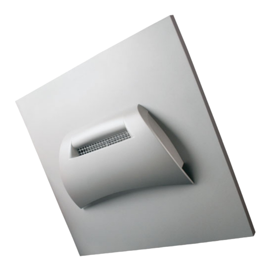
WL305
Ventilation Unit
for air extraction and recirculation
Technical specifications and installation instructions
Interior view
Elsner Elektronik GmbH Control and Automation Engineering
Herdweg 7
D – 75391 Gechingen Phone +49 (0) 70 56 / 93 97-0
Germany
Fax
+49 (0) 70 56 / 93 97-20 www.elsner-elektronik.de
info@elsner-elektronik.de
Advertisement
Table of Contents

Related Manuals for elsner elektronik WL305


Summary of Contents for elsner elektronik WL305
- Page 1 WL305 Ventilation Unit for air extraction and recirculation Technical specifications and installation instructions Interior view Elsner Elektronik GmbH Control and Automation Engineering Herdweg 7 D – 75391 Gechingen Phone +49 (0) 70 56 / 93 97-0 info@elsner-elektronik.de Germany +49 (0) 70 56 / 93 97-20 www.elsner-elektronik.de...
- Page 2 The Ventilation Unit WL305 is installed in the roof ridge area of conservatories in- stead of the normal glazing. The WL305 can be operated in air extraction and recircu- lation modes. The recirculation mode may be used for heat gain and reduction of water condensation thanks to an integrated temperature sensor in the ventilation unit.
- Page 3 1050 mm x 700 mm (W x D), thickness approx. 30 mm. The standard panel can be trimmed on three sides (see Fig. 1, page 4) Ventilation Unit WL305 • Date of issue: 25.05.2011 • Technical changes reserved. Errors reserved.
- Page 4 1.1.2. Colours Standard colours for ventilator and panel (included in price): • RAL 9016 Traffic White • RAL 9006 White Aluminium • RAL 9007 Grey Aluminium Ventilation Unit WL305 • Date of issue: 25.05.2011 • Technical changes reserved. Errors reserved.
- Page 5 Installation, inspection, commissioning and troubleshooting of the device must only be carried out by a competent electrician. Disconnect all lines to be assembled, and take safety precautions against accidental switch-on. Ventilation Unit WL305 • Date of issue: 25.05.2011 • Technical changes reserved. Errors reserved.
- Page 6 The electronic control of the venti- lator is mounted under the cover hood. When mounting and before first use, make sure the cover hood is firmly fastened to the ventilator panel. Ventilation Unit WL305 • Date of issue: 25.05.2011 • Technical changes reserved. Errors reserved.
- Page 7 2.4. Device construction Fig. 2 Panel with outside cover hood Ventilation unit with roll ventilator, flap and drives Screws M5/Allen Inside cover hood Lock hole Ventilation Unit WL305 • Date of issue: 25.05.2011 • Technical changes reserved. Errors reserved.
- Page 8 Maintenance and cleaning inside the device must only be car- ried out by a competent electrician. The device must be separat- ed from power supply then (e.g. deactivate or remove fuse). Ventilation Unit WL305 • Date of issue: 25.05.2011 • Technical changes reserved. Errors reserved.
Need help?
Do you have a question about the WL305 and is the answer not in the manual?
Questions and answers