Table of Contents
Advertisement
Quick Links
Advertisement
Table of Contents

Related Manuals for Allen-Bradley 1747-DSN


Summary of Contents for Allen-Bradley 1747-DSN
- Page 2 Reproduction of the contents of this manual, in whole or in part, without written permission of the Allen-Bradley Company is prohibited. 1991 Allen-Bradley Company, Inc. PLC, SLC Dataliner, PanelView, and RediPANEL are registered trademarks of Allen-Bradley Company, Inc.
-
Page 3: Table Of Contents
Table of Contents Distributed I/O Scanner A–B Preface Using this Manual Purpose of this Manual ........P–1 Contents of this Manual . - Page 4 Table of Contents Distributed I/O Scanner 30 I/O Block Configuration Input Image Example ....3–7 30 I/O Block Configuration Output Image ....3–8 Control Word (Word 0) .
-
Page 5: Introduction
A–B Preface Using This Manual Read this chapter to familiarize yourself with the rest of the manual. It provides information concerning the: • contents of this manual • intended audience • conventions used • warnings and cautions Purpose of this Manual This manual describes how the Distributed I/O (DIO) Scanner, Catalog Number 1747–DSN, is used in the Distributed I/O System. -
Page 6: Related Publications
Preface Related Publications The following publications are available to assist you in the use of your DIO system: • APS Library, Catalog Number 1747–ND001 Series B (shipped with Advanced Programming Software) • HHT Library, Catalog Number 1747–ND002 Series B (shipped with HHT) •... -
Page 7: Warnings And Cautions
Preface Warnings and Cautions Both warnings and cautions are used in this manual. WARNING: This symbol means people can be injured if pro- cedures are not followed. WARNING: This symbol means there is a potential shock hazard and people can be injured if procedures are not followed. -
Page 8: Chapter Objectives
Chapter A–B Introduction Chapter Objectives This chapter contains the following information: • DIO system overview • DIO Link overview • DH–485 Data Link overview • how the scanner interacts with the SLC processor • scanner features Important: Use the DIO scanner in any SLC 500 Modular Hardware system. -
Page 9: Dio Link Overview
Chapter 1 Introduction DIO Link Overview The DIO Link is an Allen–Bradley communications network supporting high speed transfer of control information. A DIO Link consists of a single master device (the scanner) and multiple slave devices (the I/O blocks). The scanner and I/O blocks are daisy chained together by a single twisted pair cable (Belden 9463). -
Page 10: Dio Scanner Features
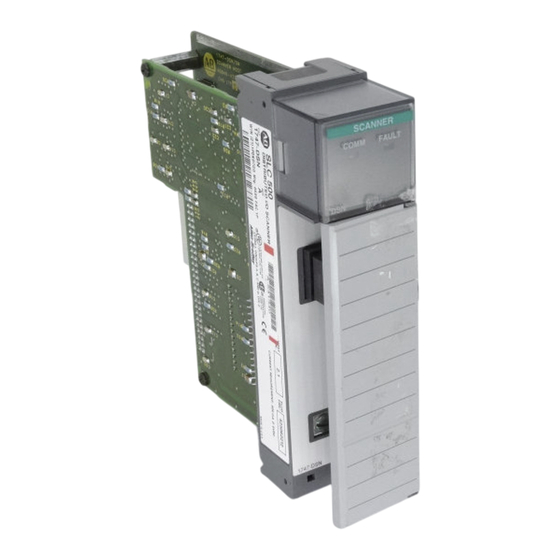
Chapter 1 Introduction DIO Scanner Features The DIO Scanner is featured below. SCANNER SCANNER FAULT LED COMM LED DIO Link Connector Chassis Ground Terminal Cable Tie LEDs Two LEDs are provided to monitor scanner and communications status. FAULT LED – used to monitor scanner status. Its normal state is off. The FAULT LED is off whenever the scanner is operating properly. -
Page 11: How The Scanner Interacts With The Slc Processor
Chapter 1 Introduction How the Scanner Interacts The SLC processor scan consists of an input, program, and output scan. with the SLC Processor During the input scan, the scanner input file (which contains the on/off input status of all configured I/O blocks) is read into SLC processor memory. During the SLC program scan, the input information is used by your application program. -
Page 12: Scanner Configurations
Chapter 1 Introduction Scanner Configurations The scanner can be configured for two different modes of operation. These modes, or configurations, are referred to as 7 and 30 I/O block configurations. When the scanner is configured for a 7 I/O block configuration, the scanner addresses up to seven I/O blocks. -
Page 13: Chapter Objectives
Chapter A–B Wiring and Installation Chapter Objectives This chapter contains the information necessary to: • select the proper DIO system components • install the scanner into the SLC Rack • wire the DIO Link Network • wire the DH–485 Data Link Network Determining Block The number of I/O blocks you require is based upon the number of input and Requirements... -
Page 14: Wiring The Dio Link
Chapter 2 Wiring and Installation Wiring the DIO Link The scanner and I/O blocks are connected to the DIO Link in a daisy chain configuration. A daisy chain configuration is formed by connecting the scanner and I/O blocks together in a serial manner along a single section of link cable (Belden 9463). - Page 15 Chapter 2 Wiring and Installation The DIO Link must be terminated at each end with an 82 Ohm 1/2 watt resistor. The resistor is connected across Line 1 and Line 2. In addition, Chassis Grounding Method One is illustrated below. SCANNER Ω...
-
Page 16: Wiring The Dh-485 Data Link
Chapter 2 Wiring and Installation Wiring the DH–485 Data The DH–485 Data Link allows a programming device to communicate with Link the SLC processor. Each I/O block has a programming port that allows a programming device to be connected to the DH–485 Data Link. The Isolated Coupler and I/O blocks are connected to the DH–485 Data Link in a daisy chain configuration. - Page 17 Chapter 2 Wiring and Installation The Isolated Coupler is attached to the DH–485 Data Link using its 6 position DH–485 Data Link connector. The I/O blocks are attached to the DIO Link using 4 of the 6 terminals on the DIO connector. The DH–485 Data Link cable shield must be earth grounded at one point on the link.
-
Page 18: Scanner Installation
Chapter 2 Wiring and Installation Scanner Installation Installation procedures for this scanner are the same as any other discrete I/O or specialty module. CAUTION: Disconnect power before attempting to install, remove, or wire the scanner. 1. Align the full sized scanner circuit board with the rack card guide. The first slot (slot 0) of the first rack is reserved for the SLC processor. -
Page 19: Chapter Objectives
Chapter A–B Configuration and Programming Chapter Objectives This chapter contains the information necessary to: • configure the SLC processor for use with the scanner • access the I/O block data in the SLC processor input and output files • configure the scanner for the correct number of I/O blocks •... -
Page 20: Slc Processor Configuration
Chapter 3 Configuration and Programming SLC Processor The scanner can be configured to communicate with a maximum of 7 or 30 Configuration I/O blocks. The 7 or 30 I/O block configuration is determined by the ID code that is entered when programming the SLC processor. SLC 5/01 processors can only use the 7 I/O block configuration. -
Page 21: Slc Processor Input And Output Images
Chapter 3 Configuration and Programming SLC Processor Input and The SLC processor input and output images for the scanner are dependent Output Images upon whether the 7 I/O block or 30 I/O block configuration is selected. 7 I/O Block Configuration Input Image The 7 I/O block configuration input image consists of eight words (one communication status word and seven input words). -
Page 22: 7 I/O Block Configuration Output Image
Chapter 3 Configuration and Programming 7 I/O Block Configuration Output Image The 7 I/O block Configuration Output Image consists of eight words (one control word and seven output words). Each output word corresponds to an I/O block address. For example, the output data for I/O block 7 is located in output word 7. -
Page 23: 7 I/O Block Configuration Output Image Example
Chapter 3 Configuration and Programming Configuration Data Valid Bit – Bit 10 of the Control Word (word 0) must be set after bits 0 – 4 (Number of I/O blocks) are valid. When this bit is first set to 1 (from within the run mode), bits 0 – 4 (Number of I/O blocks) are used to configure the scanner with the number of I/O blocks connected. -
Page 24: 30 I/O Block Configuration Input Image
Chapter 3 Configuration and Programming 30 I/O Block Configuration Input Image The 30 I/O block configuration input image consists of 32 words (two communication status words and 30 input words). Each input word has a corresponding I/O block address. For example, the input data for I/O block 31 (there is no I/O block 16) is located in input word 31. - Page 25 Chapter 3 Configuration and Programming 30 I/O Block Configuration Input Image Example Bits 1 – 15, I/O block communication Bit 0, Overall communication status for status for I/O blocks 1 – 15 I/O blocks 1–15 and 17–31 Bit Number (decimal) Input File I/O block Communication Status, Word 0 I:e.0...
- Page 26 Chapter 3 Configuration and Programming 30 I/O Block Configuration Output Image The 30 I/O block configuration output image consists of 32 words (one control word, one reserved word, and 30 output words). Each output word has a corresponding I/O block address. For example, the output data for I/O block 31 (there is no I/O block 16) is located in output word 31.
-
Page 27: 30 I/O Block Configuration Output Image Example
Chapter 3 Configuration and Programming Configuration Data Valid Bit – Bit 10 of the Control Word (word 0) must be set after bits 0 –4 (Number of I/O blocks) are valid. When this bit is first set to 1 (from run mode), bits 0 – 4 are used to configure the scanner with the number of I/O blocks connected to the scanner. -
Page 28: Use Of The Communication Status Words
Chapter 3 Configuration and Programming Use of the Communication The bits in the Communication Status Word(s) indicate whether or not the Status Words scanner is communicating with each of the configured I/O blocks. Each bit in the Communication Status Word(s) corresponds to an I/O block. If the scanner is communicating with an I/O block, the corresponding bit in the Communication Status Word is set to 1. -
Page 29: Application Example
Chapter 3 Configuration and Programming The Output Disable bit can be used anytime that the SLC processor is in run mode. The bit has no effect when the processor is in program/test/fault mode. The Output Disable bit is not affected by, and does not affect, the bits for Data Valid or Number of I/O Blocks. -
Page 30: Programming Example Using 7 I/O Block Configuration
Chapter 3 Configuration and Programming Programming Example Using 7 I/O block Configuration In the following programming example, the first rung is used to initiate the DIO system using the Output Control Word. The scanner is located in slot 1 and an alarm is connected to a discrete I/O card in slot 2. When the water level drops, the switch closes and the pump starts pumping water into the tower. -
Page 31: Chapter Objectives
Chapter A–B Operation and Troubleshooting Chapter Objectives This chapter will provide information on : • scanner start–up • scanner normal operation • scanner test mode operation • scanner slot disable operation • I/O block hold last state operation • scanner and I/O block status LEDs •... -
Page 32: Normal Operation
Chapter 4 Operation and Troubleshooting Normal Operation During normal operation, the LEDs are illuminated as shown below: SCANNER COMM FAULT FAULT LED is off COMM LED is solid green When the SLC processor is taken out of run mode, the COMM LED remains solid green. -
Page 33: Scanner Slot Disable Operation
Chapter 4 Operation and Troubleshooting Scanner Slot Disable CAUTION: Operation Make sure that you clearly understand the implications of disabling a scanner module slot before utilizing this feature. The scanner slot disable operation is the same in the 7 I/O and 30 I/O block configurations. -
Page 34: Scanner Test Mode Operation
Chapter 4 Operation and Troubleshooting Scanner Test Mode The scanner test mode operation is different for the 7 I/O block and 30 I/O Operation block configurations. 30 I/O block Configuration For the 30 I/O block configuration, the Number of I/O Blocks and Configuration Data Valid bits will operate in test mode in the same manner as they operate in run mode. -
Page 35: I/O Block Hold Last State Operation
Chapter 4 Operation and Troubleshooting I/O Block Hold Last State Operation During normal operation, the I/O block outputs reflect the SLC processor output image. However, there are several conditions under which the I/O block outputs will not reflect the SLC processor output image, but will either be reset to 0 or will hold their last state. -
Page 36: Status Leds
Chapter 4 Operation and Troubleshooting Status LEDs The scanner has two LEDs that indicate its operating status, FAULT and COMM. The FAULT LED indicates the scanner’s overall status. The COMM LED indicates the DIO Link communications status. The FAULT LED is off whenever the scanner is operating properly. The COMM LED state is valid only when the FAULT LED is off. -
Page 37: Troubleshooting
Chapter 4 Operation and Troubleshooting Troubleshooting When the scanner’s LEDs change state, use the following table to isolate the cause. COMM FAULT Problem Solution Condition FAULT LED Configured for an invalid Modify DIO initialization rung in SLC SCANNER flashing red number of I/O blocks. -
Page 38: Error Codes
Chapter 4 Operation and Troubleshooting Error Codes Error codes are reported in word 6 of the SLC processor status file. The format of the status word and applicable error codes are shown below: Slot Number Error Code 01H to 1EH The table below lists and explains the possible errors that you may encounter using an SLC 5/01 or 5/02 processor with the DIO scanner. -
Page 39: Chapter Objectives
Chapter A–B Specifications Chapter Objectives This chapter provides the scanner specifications. Scanner Operating Specifications Backplane Current Consumption 900 mA @ 5VDC ° ° ° ° Operating Temperature F to 131 F (0 C to +55 ° ° ° ° Storage Temperature –40 F to 185 F (–40...
Need help?
Do you have a question about the 1747-DSN and is the answer not in the manual?
Questions and answers